Transcription
OSSIMSensor Model CapabilitiesOSSIM Sensor ModelingOscar Kramer, Kramer Analytic, LLC.ScopeThis document is intended for OSSIM software developers and describes the initial implementation of the imaging-sensormodeling capability within the OSSIM package.Contents OVERVIEW SPECIFICATION CONVENTIONS IMPLEMENTATION INTRODUCTION APPENDICESOverviewThis application provides OSSIM the ability to mathematically model the imaging process including the physical sensor isrequired in order to perform such functions as ortho-rectification, elevation extraction, and 3-D target position determination.It also provides the ability to determine and correct for image acquisition errors given some reference "ground truth"information, commonly referred to as registration.ConventionsThe following typeface conventions and symbols are used in this guide:ossimSensorModel(const ossimKeywordlist& geom kwl)Constructor initializes all data members from the geometry file stored as a keyword list.Courier font indicates code. The next line after the code is code reference.Press Ctrl EscMonotype font indicates system display (screens, messages, keyboard input). Indicates coding instructions. Yes it looks like a copyright symbol . . . so1
OSSIMSensor Model CapabilitiesCurrent LimitationsAdditional information.IntroductionSensor modeling is somewhat of a misnomer since what is being modeled is the entire acquisition process, not just thephysical sensor. Other sensor model considerations might include atmospheric refraction effects, ground station processing(when the image is resampled into a map projection), and platform biases (such as misalignment of the camera relative to theaircraft's centerline). In effect, the goal of a sensor model is to capture the entire process of acquiring an image, and thereforebe able to accurately map a pixel on the image to a point on the ground. Furthermore, as implemented in OSSIM, a sensormodel also provides the capability of adjusting critical parameters to correct for observed geometric errors on the image.In general, a sensor model implementation is specific to a particular sensor type. For example, a whisk-broom type sensorsuch as the LandSat series would require one sensor model implementation. It should be possible to re-use thatimplementation for other whisk-broom satellites. Only the values for parameters such as ground sample distance (GSD),pointing angle, etc., would change; the projection equations stay the same. Other sensor models types include the framecamera, push-broom, pin-hole (for perspective scene generation), synthetic aperture radar (SAR), and other variations onthese.There is also another class of sensor models termed "replacement model" which consist of replacing the rigorous projectionequations (that model the physical processes) with approximation functions whose parameters are essentially divorced fromphysical interpretation. These include polynomials, ratio of polynomials, geometric series, etc.A third class of sensor model is termed "interpolation model" and consists of a collection of numerical "grids," covering theimage, that are interpolated in a bilinear fashion to arrive at the desired projection solution. This model may still containparameters directly related to the physics of the acquisition, and therefore cannot be considered a true replacement model.The grids are initialized with the corresponding rigorous model. The advantage gained is in speed of execution, since theprojection solution is a simple linear computation versus a complicated, non-linear, rigorous equation.For detailed software implementation notes, the reader is directed to the OSSIM Doxygen web-based documentation thatmust be generated locally using the Doxygen input file found in the top directory of the source distribution along with theDoxygen executable. See www.doxygen.org for more information and downloads. The latest Doxygen build is also availableat http://trac.osgeo.org/ossim/doxygen .SpecificationsFunctional RequirementsSoftware RequirementsUnix/Linux O/S with appropriate C compiler, ORWindows XP with Visual Studio 2005 or betterLimitationsThe first implementation of sensor modeling in OSSIM contains limitations that need to be addressed in order to provide thefunctionality necessary for advanced GIS and image processing including the following:2
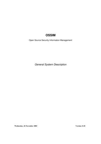
OSSIMSensor Model CapabilitiesError Modeling: The lack of statistical modeling prevents the implementation of statistical-based algorithms such as leastsquares registration, geopositioning, elevation extraction and any other algorithms requiring error propagation.Rigorous Sensor Models: While a few rigorous models are currently available, new models will need to be added as timeand funding permits.FeaturesExisting OSSIM ModelsThis section provides descriptions and special notes on sensor models currently implemented in OSSIM.Updating Sensor ModelsThis document should be amended by the programmer with each new sensor model implemented, with a description of theimplementation, including the adjustable parameters and any limitations.ossimCoarseGridModelThis was the first concrete model implemented in OSSIM; it is an interpolation model. The adjustable parameters areestablished identical to the rigorous model used to create the grids. There are several interpolation grids that are referenced tocompute a ground point from an image point. The first pair of grids are the latitude and longitude grids. A second paircontains the partial derivatives of latitude and longitude w.r.t. height. These define the horizontal shift with respect to avertical movement along the imaging ray, and are used for intersecting the ray with an elevation surface. The remaininggrids contain the partial derivatives of latitude and longitude w.r.t. the adjustable parameters. These define the horizontalshift corresponding to a parameter adjustment.InterfaceThis section describes the sensor model base-class interface. It also discusses the typical usage within OSSIM, including thefactory-based instantiation utility. Please refer to the Doxygen pages for more up-to-date information.ossimSensorModel Base ClassThe ossimSensorModel class is the base class for all sensor models in OSSIM. It is derived from ossimProjection which inturn is derived from ossimObject. As an ossimProjection-derived class, it contains methods for projecting a two-dimensionalpoint to a three-dimensional "world" coordinate system represented by latitude/longitude/height, and projecting back fromworld to two-dimensions.As an ossimObject-derived type, it implements the state save and load functionality for the state common to all sensormodels. It also contains the runtime type interface (RTTI) capability for down-casting. Figure 2.1 illustrates the classhierarchy. Note the placement of ossimMapProjection which is the base class for all map projections. In this sense, sensormodels are analogous to map projections in that they can be referenced for performing the 2D to 3D (and reverse)transforms.3
OSSIMSensor Model CapabilitiesClass HierarchyInterface Summary: ossimSensorModelossimSensorModel(const ossimKeywordlist& geom kwl)Constructor initializes all data members from the geometry file stored as a keyword list. This is intended forconstruction given a dedicated geometry file. Note that there is no support for a prefix. If the geometry keywords areprefixed, the sensor model should be instantiated via the default constructor, and then initialized through a call toloadState(keywordlist, prefix).ossimGpt origin() constReturns the image’s ground reference point data member. This is typically the center of the image, but is dependenton the concrete class' definition. It could also be the upper-left corner, the origin of the line/sample coordinatesystem, for example.void lineSampleToWorld(const ossimDpt& lineSampPt, ossimGpt& worldPt) constThis method computes the lat/lon/height of a 3D point given the 2D line/sample coordinates. It is implemented in theossimSensorModel base class as an iterative solution using the pure virtual method worldToLineSample()implemented in the derived concrete classes. It is provided for convenience, however, the concrete class shouldimplement a more efficient rigorous solution if available.void worldToLineSample(const ossimGpt& worldPt, ossimDpt& lineSampPt) constPure VirtualThis method, to be implemented by the derived concrete sensor models, implements the 3D to 2D projectiontransform.void lineSampleHeightToWorld(const ossimDpt& projectedPoint,const double&elevation,ossimGpt&worldPt) constPure VirtualThis method, to be implemented by the derived concrete sensor models, implements the 2D to 3D reverse projectiontransform given an elevation.4
OSSIMSensor Model Capabilitiesvirtual ostream& print(ostream& out) constStream output utility method dumps the data members.Base Class Data Member Access MethodsThe members include the image size in lines and samples, the adjustable parameters, the associated parameter uncertainties,as well as the parameter names and corresponding units simString&imageSize() constgetAdjustableParam(int index) constsetAdjustableParam(int index, const double& value)getParamSigma(int index) constsetParamSigma(int index, const double& value)getParamName (int index) constgetParamUnits(int index) constvirtual bool saveState(ossimKeywordlist& kwl, const char* prefix 0) constvirtual bool loadState(const ossimKeywordlist& kwl, const char* prefix 0)These methods implement the ossimObject pure virtual methods for saving and restoring the object's state.Typical UsageThe ossimSensorModel and derived classes can be used anywhere a model-based projection transform is needed. Within theossim viewer application, the sensor model comprises one component of the image renderer tile source. The image renderer(ossimImageRenderer) utilizes an instance of an ossimImageViewProjectionTransform object. This object performs the inputimage line/sample to output view line/sample -- and reverse -- conversions necessary for rendering an image. This transformowns two instances of ossimProjection-derived classes, one for the input image-to-world projection, and the second for theworld-to-view projection. The intermediate "world" space is unique to the ossimImageViewProjectionTransform class. Otherimage-view transforms (IVT's) perform 2D-to-2D without reference to a world space.The typical application is to plug a sensor model in for the input projection, and some map projection in for the output viewprojection. The renderer can then relate the output space to the input file space. Given an elevation surface, the renderer canthus generate an ortho-rectified product to any of the supported map projections.The image-to-view transformation however can take on many configurations. One can, for example, plug an instance of, say,a pin-hole sensor model projection into the output side of the IVT to produce a perspective scene given the input "texturemap" image.Factory-based InstantiationThe typical operational scenario for viewing imagery is for the operator to select an image and associated geometry file forviewing in a particular map projection. Or the operator may select a keyword list session file that specifies these items. It istherefore necessary for the software to identify the proper projections (including map and sensor model projections) toinstantiate given some type specification or a filename. The factory pattern is used in OSSIM to handle the creation of theseobjects.The Factory design pattern, as implemented in OSSIM, begins with a templated base class namedossimFactoryBaseTemplate. This template declares two create() methods that return a pointer to the product object. The firstversion of create() takes a keyword list reference along with a prefix string. The second version takes a string. It is really upto the programmer to decide how to implement these two methods in the derived concrete factory classes.5
OSSIMSensor Model CapabilitiesFor projections, there is the ossimProjectionFactory class which owns two sub-factories: an ossimMapProjectionFactory andan ossimSensorModelFactory. The create() methods for the "super-factory" simply call the create() methods of its two subfactories. The value returned assuming no difficulties were encountered will be a pointer to the desired ossimProjectionobject. The sensor model factory implements its create() methods as follows;Given a keyword list reference, the sensor model factory will search for the occurrence of the "type" keyword. The valueexpected is the object name of the desired sensor model, for example, "ossimCoarseGridModel." If the label is found tomatch the list of available sensor models, the factory will instantiate that model object, and pass along that keyword list andprefix to the model's loadState() method. The factory then returns the pointer to the fully initialized model to the callingmodule. If no matching label is found, the factory returns a null pointer.The second form of create() accepts an ossimString argument. The factory interprets this string in two ways. First it checks tosee if the string corresponds to an existing disk file. If so, it attempts to instantiate one sensor model type after another,checking the status of each to see if they successfully initialized themselves given the presumed geometry file. If a modelindicates an error occurred loading the geometry file, the factory assumes it was not the appropriate model, and it deletes thatinstance then tries again with the next model type it knows about. The factory returns the pointer to the successfullyconstructed model, otherwise it returns a null value. If the string argument to create() is not a filename, then the factoryassumes the string contains the object name as would be found in a keyword list next to the "type" keyword.ImplementationThis section is intended for the developer tasked with implementing a new sensor model into OSSIM, or with modifying anexisting model. It presents important design details that will hopefully help standardize sensor modeling in OSSIM. Thesection describing the class interface (Section 2.1) already enforces much of the guidelines for creating a new model, but adiscussion of some of the more subtle aspects will help prevent incompatible implementations.Geometry Files and ConstructionThere are a number of ways the geometry of an image can be communicated to the processing software. It can be providedas a separate geometry file formatted as a keyword list. Or it can be embedded in a larger keyword list session file with anassociated prefix to tag the corresponding geometry keywords. The geometry information can also form part of the imagefile's header, as found in GeoTiff and NITF formatted imagery. In order to insure the maximum flexibility, a sensor modelimplementation should be designed to handle as many formats as will be expected given the imagery type. The sensor modelmust have a default constructor that will be referenced by the factory. This default constructor does not need to do anything,since the factory will also call the object's loadState() method soon after construction. The loadState() method must be ableto fully initialize the model from a keyword list. A second constructor accepting a keyword list directly (but no prefix)provides a short-cut to loading a state. In fact, the constructor with keyword list argument will typically just call itsloadState() to complete construction.A third constructor accepting an ossimFilename must be provided for proper interfacing to the sensor model factory. Thisconstructor will open the named file and presume it is a geometry file. The format of the geometry file in OSSIM shouldgenerally be a keyword list as generated by that model's saveState() method. However, as mentioned above, other nonkeyword list formats may exist, and the constructor should determine the format and parse the file accordingly. A goodexample of this can be found in ossimCoarseGridModel, where a proprietary format geometry file can be parsed as well as adedicated OSSIM keyword list.More constructors can be added by the developer if desired. The three specified here are the minimum required to insurecompatibility with the factory design currently implemented.Proprietary FormatsOSSIM provides conversion routines to convert proprietary formats to OSSIM formats.6
OSSIMSensor Model CapabilitiesAdjustable ParametersThe discussion of adjustable parameters is necessary only if the developer intends for the model to be used within an imageregistration function or related application. If the goal of the model is simply to project from 2D image space to 3D worldspace without ever adjusting the acquisition parameters, then the model can be constructed without regard to adjustableparameters. Note, however, that the base class ossimSensorModel is derived from ossimAdjustableParameterInterface, sothat functionality will be picked up nevertheless, though it will be ineffectual. The non-adjustable model will simply declarethat its number of adjustable parameters is zero.It is necessary to separate the discussion of adjustable parameters into two areas: rigorous models and replacement models.As mentioned earlier, sensor models can be implemented either as rigorous models, as interpolation models, or asreplacement models. If the interpolation model grid was generated using a rigorous model, then it can be consideredessentially a rigorous model as well. The distinction is fundamental when one considers the adjustable parameters to selectfor a given implementation.Rigorous models are just that: they model the imaging ray from the sensor, through the optics (or antenna in the case ofSAR), down to the ground with a set of rigorous equations. In order to correct for errors in acquisition, the analyst, prior toimplementing the sensor model, must identify what these sources of error are that affect the final orientation of the imagingray in space. These error sources are then parameterized in the projection equations. Given some reference data, theseparameters can then be adjusted so as to minimize the residual geometric error in the image. So for a rigorous model, it iscrucial that the analyst select the proper set of adjustable parameters that capture all the sources of error down to the subpixel level. Furthermore, these parameters must be sufficiently independent of each other to avoid redundant adjustments andpotential numerical problems. For example, a simple aerial frame camera model would implement adjustable parameters forthe platform position and attitude (six parameters total). It would be tempting to include another for focal length, but thisparameter manifests similarly to a change in flight altitude already represented in the position vector. This introduces aredundancy for an optimizer in a registration program trying to minimize the residuals between a pair of images.Furthermore, while the exposure position and attitude have a relatively large random component that effectively decorrelatesthe measurements for a pair of images, the focal length will remain virtually unchanged (assuming it is the same sensor forboth images). This is an example of selecting the model’s adjustable parameters wisely. Again, if your application doesn’tplan on ever being used within a registration application, these considerations are moot.A bit more troublesome are the replacement models, since they are intended to hide the physics inside a black box ofabstract formulation. This is a non-trivial problem that is still to be worked out.Adjustable parameters as implemented in the projection equations should be zero-biased. For example, in the case of an offNADIR frame camera shot, where the camera is pointing off to the side of the aircraft, the roll angle parameter should beseparate from the off-NADIR angle variable, and should be zero-biased. The off-NADIR pointing angle would be aconstant and given in the support data, while the roll angle would be an adjustable parameter and initialized to zero. Ofcourse the two are directly related, but only one is considered an adjustable parameter. Adjustable parameters are maintainedby the ossimSensorModel base class as an array of doubles.Associated with each adjustable parameter is its error uncertainty, or sigma value. This quantity indicates the standarddeviation uncertainty of the adjustable parameter initial value (of zero). Sometimes these quantities are provided by theacquisition system operator or manufacturer, but usually one must take a hopeful guess at these sigmas and then experimentwith adjustments to see the range of error actually observed with each parameter over many image samples.Along with the adjustable parameters and their sigma values, there are two arrays in ossimSensorModel for storing the nameof the parameter and the units associated with the parameter. Both of these are stored as ossimStrings. It is encouraged tomake use of these since their values are written out by ossimSensorModel::saveState() and greatly help improve thereadability of the geometry files.7
OSSIMSensor Model CapabilitiesRigorous versus Iterative ProjectionPresently, the ossimSensorModel base class implements an iterative solution within the lineSampleToWorld() method forcomputing a ground point given a line and sample. This scheme uses the derived-class' worldToLineSample() method,iterating until the solution converges on (hopefully) the right answer. This base-class implementation is provided forconvenience, so that the programmer need only implement the worldToLineSample() method in the concrete class.However, since iterating on rigorous projection equations can get computationally expensive, the programmer is encouragedto override this method with a rigorous implementation if the transform is possible. Adding New Sensor Models to OSSIMThis section is provided to help the programmer implement a new sensor model by presenting a step-by-step process andchecklist. This is not meant as a guide for developing the projective equations or selecting adjustable parameters. It is onlyfor insuring the sensor model complies with the OSSIM design approach and properly interfaces to the rest of the code.1.It is easiest to adapt an existing model. Copy ossimCoarseGridModel.h/cc to a new directory underossim core/projections/sensor modeling. Also copy the Makefile and the test directory. The new directoryshould be named after the sensor class (or similar, without the "ossim" prefix).2.Replace the occurrence of the ossimCoarseGridModel string with the name of the new model in all the new files.3.Edit the .h and .cc files with the new implementation. The non-virtual methods found in ossimCoarseGridModelare specific to that implementation and can be deleted. Remember that the factory will be expecting the threeconstructor forms found in ossimCoarseGridModel, so make sure those are provided. The constructor taking anossimString can interpret that string either as a filename, a model specification (name), or both.4.Make sure that the new model's saveState() and loadState() methods completely represent the object's state, andthat control is passed to the base class' saveState() and loadState() as well.5.Edit ossimSensorModelFactory.cc and search for the comment "ADD MODEL". At each of these locations,observe the existing code and duplicate the pattern for the new model.6.Make sure that in ossimSensorModelFactory::createFromFile() the model instance is deleted and the pointer set toNULL after the if-test.7.Go into the test directory and rename and edit the .cc file (and Makefile). In the test program, try constructing themodel various ways including using the factory. Also project various points across the image down to theground and back to test round trip error. Note that this only tests the internal consistency of the model and notwhether the model is accurate. Other tests will be necessary to fully validate the implementation.With the model implemented and the factory updated, the OSSIM applications should be ready to process with the newsensor model.Appendix -- Explanation of TermsOSSIM (Open Source Software Image Map)The open-source development effort led by ImageLinks to produce a powerful GIS and image processing software package.Information is available at www.ossim.org.8
OSSIMSensor Model CapabilitiesOCG (OSSIM Coarse Grid)This is the acronym used when referring to the coarse grid model implementation in OSSIM.9
Existing OSSIM Models This section provides descriptions and special notes on sensor models currently implemented in OSSIM. Updating Sensor Models This document should be amended by the programmer with each new sensor model implemented, with a description of the implementation, including the adjustable parameters and any limitations.