Transcription
CEMABELT BOOKFIFTH EDITIONCHAPTER 6BELT TENSION, POWER, ANDDRIVE ENGINEERINGAS REFERENCEDOCCASIONALLYINCEMABELT BOOKSIXTH EDITION
CHAPTER 6Belt Tension, Power,and Drive EngineeringBasic power requirementsBelt tension calculationsCEMA horsepower formulaDrive pulley relationshipsDrive arrangementsMaximum and minimum belt tensionsTension relationships and belt sag between idlersAcceleration and deceleration forcesAnalysis of acceleration and deceleration forcesDesign considerationsConveyor horsepower determination — graphical methodExamples of belt tension and horsepower calculations — six problemsBelt conveyor drive equipmentBackstopsBrakesBrakes and backstops in combinationDevices for acceleration, deceleration, and torque controlBrake requirement determination (deceleration calculations)85
Belt Tension, Power, and Drive EngineeringThe earliest application engineering of belt conveyors was, to a considerableextent, dependent upon empirical solutions that had been developed by various manufacturers and consultants in this field. The belt conveyor engineering analysis, information, and formulas presented in this manual represent recent improvements in theconcepts and data which have been developed over the years, using the observationsof actual belt conveyor operation and the best mathematical theory.Horsepower (hp) and tension formulas, incorporating successively all the factorsaffecting the total force needed to move the belt and its load, are presented here in amanner that permits the separate evaluation of the effect of each factor. These formulas represent the consensus of all CEMA member companies.In recent years, CEMA member companies have developed computer programscapable of complete engineering analysis of the most complex and extensive belt conveyor systems. These programs are more comprehensive and include more extensiveanalysis and calculations than can be included in this manual. Although the programsare treated as proprietary information, each CEMA member company welcomes anopportunity to assist in the proper application of belt conveyor equipment. Oneadvantage of using computer programs is the speed and accuracy with which theyprovide information for alternate conveyor designs.Basic Power RequirementsThe horsepower, hp, required at the drive of a belt conveyor, is derived from thepounds of the effective tension, Te , required at the drive pulley to propel or restrainthe loaded conveyor at the design velocity of the belt V, in fpm:(1)T Vehp -----------------33, 000To determine the effective tension, Te , it is necessary to identify and evaluate eachof the individual forces acting on the conveyor belt and contributing to the tensionrequired to drive the belt at the driving pulley. Te is the final summarization of thebelt tensions produced by forces such as:1. The gravitational load to lift or lower the material being transported.2. The frictional resistance of the conveyor components, drive, and all accessorieswhile operating at design capacity.3. The frictional resistance of the material as it is being conveyed.4. The force required to accelerate the material continuously as it is fed onto the con-veyor by a chute or a feeder.86
Belt Tension CalculationsThe basic formula for calculating the effective tension, Te , is:T e LK t ( K x K y W b 0.015W b ) W m ( LK y H ) T p T am T ac (2)Belt Tension CalculationsThe following symbols will be used to assist in the identification and evaluationof the individual forces that cumulatively contribute to Te and that are therefore components of the total propelling belt tension required at the drive pulley:Ai belt tension, or force, required to overcome frictional resistance androtate idlers, lbs (see page 91)C1 friction modification factor for regenerative conveyorH vertical distance that material is lifted or lowered, ftKt ambient temperature correction factor (see Figure 6.1)Kx factor used to calculate the frictional resistance of the idlers and the sliding resistance between the belt and idler rolls, lbs per ft (see equation 3,page 91)Ky carrying run factor used to calculate the combination of the resistance ofthe belt and the resistance of the load to flexure as the belt and load moveover the idlers (see equation 4, page 94, and Table 6-2). For return runuse constant 0.015 in place of Ky . See Tyr .Llength of conveyor, ft Q tons per hour conveyed, tph, short tons of 2,000 lbsSi troughing idler spacing, ftTac total of the tensions from conveyor accessories, lbs:T ac T sb T pl T tr T bcTam tension resulting from the force to accelerate the material continuously asit is fed onto the belts, lbsTb tension resulting from the force needed to lift or lower the belt, lbs (seepage 116):T b H W b87
Belt Tension, Power, and Drive EngineeringTbc tension resulting from belt pull required for belt-cleaning devices such asbelt scrapers, lbsTe effective belt tension at drive, lbsTm tension resulting from the force needed to lift or lower the conveyedmaterial, lbs:T m H W mTp tension resulting from resistance of belt to flexure around pulleys and theresistance of pulleys to rotation on their bearings, total for all pulleys, lbsTpl tension resulting from the frictional resistance of plows, lbsTsb tension resulting from the force to overcome skirtboard friction, lbsTtr tension resulting from the additional frictional resistance of the pulleysand the flexure of the belt over units such as trippers, lbsTx tension resulting from the frictional resistance of the carrying and returnidlers, lbs:T x L Kx KtTyb total of the tensions resulting from the resistance of the belt to flexure asit rides over both the carrying and return idlers, lbs:T yb T yc T yrTyc tension resulting from the resistance of the belt to flexure as it rides overthe carrying idlers, lbs:T yc L K y W b K tTym tension resulting from the resistance of the material to flexure as it rideswith the belt over the carrying idlers, lbs:T ym L K y W mTyr tension resulting from the resistance of the belt to flexure as it rides overthe return idlers, lbs:T yr L 0.015 W b K tV 88design belt speed, fpm
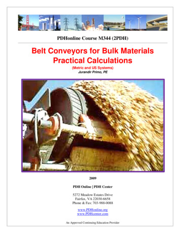
Belt Tension CalculationsWb weight of belt in pounds per foot of belt length. When the exact weight ofthe belt is not known, use average estimated belt weight (see Table 6-1)Wm weight of material, lbs per foot of belt length:Q 2, 00033.33 QW m ------------------------- -----------------------60 VVThree multiplying factors, Kt , Kx , and Ky , are used in calculations of three of thecomponents of the effective belt tension, Te .Kt — Ambient Temperature Correction FactorIdler rotational resistance and the flexing resistance of the belt increase in coldweather operation. In extremely cold weather the proper lubricant for idlers must beused to prevent excessive resistance to idler rotation.Ambient temperature ºF conveyor operationOperation at temperatures below –15ºF involves problems in addition to horsepower considerations.Consult conveyor manufacturer for advice on special belting, greasing, and cleaning specifications andnecessary design modification.Figure 6.1 Variation of temperature correction factor, Kt , with temperature.Kt is a multiplying factor that will increase the calculated value of belt tensions toallow for the increased resistances that can be expected due to low temperatures. Figure 6.1 provides values for factor Kt .89
Belt Tension, Power, and Drive EngineeringKx — Idler Friction FactorThe frictional resistance of idler rolls to rotation and sliding resistance betweenthe belt and the idler rolls can be calculated by using the multiplying factor Kx . Kx isa force in lbs/ft of conveyor length to rotate the idler rolls, carrying and return, and tocover the sliding resistance of the belt on the idler rolls. The Kx value required torotate the idlers is calculated using equation (3).The resistance of the idlers to rotation is primarily a function of bearing, grease,and seal resistance. A typical idler roll equipped with antifriction bearings and supporting a load of 1,000 lbs will require a turning force at the idler roll periphery offrom 0.5 to 0.7 lbs to overcome the bearing friction. The milling or churning of thegrease in the bearings and the bearing seals will require additional force. This force,however, is generally independent of the load on the idler roll.Under normal conditions, the grease and seal friction in a well-lubricated idlerwill vary from 0.1 to 2.3 lbs/idler, depending upon the type of idler, the seals, and thecondition of the grease.Sliding resistance between the belt and idler rolls is generated when the idler rollsare not exactly at 90 degrees to the belt movement. After initial installation, deliberateidler misalignment is often an aid in training the belt. Even the best installations havea small requirement of this type. However, excessive idler misalignment results in anextreme increase in frictional resistance and should be avoided.Table 6-1. Estimated average belt weight, multiple- and reduced-ply belts, lbs/ft.Material Carried, lbs/ft3Belt Widthinches 09630.035.038.01. Steel-cable belts — increase above value by 50 percent.2. Actual belt weights vary with different constructions, manufacturers, cover gauges, etc. Usethe above values for estimating. Obtain actual values from the belt manufacturer wheneverpossible.Some troughing idlers are designed to operate with a small degree of tilt in thedirection of belt travel, to aid in belt training. This tilt results in a slight increase insliding friction that must be considered in the horsepower formula.90
Belt Tension CalculationsValues of Kx can be calculated from the equation:AK x 0.00068 ( W b W m ) -----i , lbs tension per foot of belt lengthSiAiAiAiAiAi (3)1.5 for 6" diameter idler rolls, CEMA C6, D61.8 for 5" diameter idler rolls, CEMA B5, C5, D52.3 for 4" diameter idler rolls, CEMA B4, C42.4 for 7" diameter idler rolls, CEMA E72.8 for 6" diameter idler rolls, CEMA E6For regenerative declined conveyors, Ai 0.The Ai values tabulated above are averages and include frictional resistance torotation for both the carrying and return idlers. Return idlers are based on single rolltype. If two roll V return idlers are used, increase Ai value by 5%. In the case of longconveyors or very high belt speed (over 1,000 fpm) refer to CEMA member companies for more specific values of Ai .Ky — Factor for Calculating the Force of Belt and Load Flexure over the IdlersBoth the resistance of the belt to flexure as it moves over idlers and the resistanceof the load to flexure as it rides the belt over the idlers develop belt-tension forces. Kyis a multiplying factor used in calculating these belt tensioning forces.Table 6-2 gives values of Ky for carrying idlers as they vary with differences in theweight/ ft of the conveyor belt, Wb ; load, Wm ; idler spacing, Si ; and the percent ofslope or angle that the conveyor makes with the horizontal. When applying idler spacing, Si , other than specified in Table 6-2, use Table 6-3 to determine a corrected Kyvalue.Example 1. For a conveyor whose length is 800 ft and (Wb Wm) 150 lbs/fthaving a slope of 12%, the Ky value (Table 6-2) is .017. This Ky value is correct only forthe idler spacing of 3.0 ft. If a 4.0-foot idler spacing is to be used, using Table 6-3 andthe Ky reference values at the top of the table, the Ky of .017 lies between .016 and .018.Through interpolation and using the corresponding Ky values for 4.0- foot spacing,the corrected Ky value is .020.Example 2. For a conveyor whose length is 1,000 ft and (Wb Wm) 125 lbs/ftwith a slope of 12%, the Ky value (Table 6-2) is .0165. This value is correct only for3.5-foot spacing. If 4.5-foot spacing is needed, Table 6-3 shows that .0165 lies between.016 and .018 (reference Ky). Through interpolation and using the corresponding Kyvalues for 4.5-foot spacing, the corrected Ky value is .0194.91
Belt Tension, Power, and Drive EngineeringTable 6-2. Factor Ky values.Percent .0160.0160.0160.018Approximate DegreesConveyor Length(ft)250400500600800Wb 200.0170.0160.0160.018Idler spacing: The above values of Ky are based on the following idler spacing (for other spacing, see Table 6-3).(Wb Wm), lbs per ft92Si , ft(Wb Wm), lbs per ftSi , ftLess than 504.5100 to 1493.550 to 994.0150 and above3.0
Belt Tension CalculationsTable 6-2. Factor Ky values.Percent .0160.0160.0160.018Approximate DegreesConveyor Length(ft)10001400200024003000Wb 180.0160.0160.0160.0160.0160.0160.018Idler spacing: The above values of Ky are based on the following idler spacing (for other spacing, see Table 6-3).(Wb Wm), lbs per ftSi , ft(Wb Wm), lbs per ftSi , ftLess than 504.5100 to 1493.550 to 994.0150 and above3.0Ky values in Tables 6-2 and 6-3 are applicable for conveyors up to 3,000 ft longwith a single slope and a 3% maximum sag of the belt between the troughing andbetween the return idlers. The return idler spacing is 10 ft nominal and loading of thebelt is uniform and continuous.93
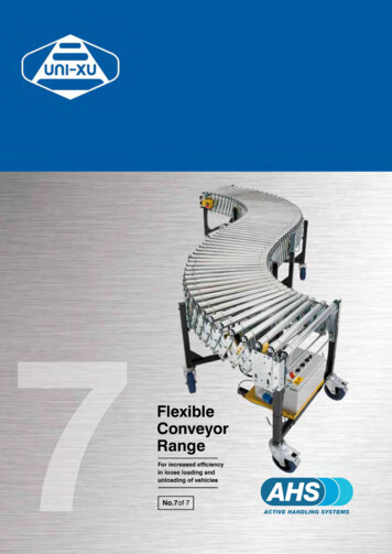
Belt Tension, Power, and Drive EngineeringEquation (4) provides Ky values for the carrying idlers of belt conveyors whoselength, number of slopes, and/or average belt tensions exceed the limitations specified above for the conveyors covered by Tables 6-2 and 6-3. This equation is applicable for conveyors in which the average belt tension is 16,000 lbs or less. To determinethe Ky factor for use in calculating conveyors of this class, it is necessary, first, toassume a tentative value for the average belt tension. The graphical method for determining conveyor horsepower (pages 141 through 145) may be of assistance in estimating this initial tentative value of average belt tension.After estimating the average belt tension and selecting an idler spacing, refer toTable 6-4 to obtain values for A and B for use in the following equation:K y ( W m W b ) A 10–4 B 10–2(4)By using equation (4), an initial value for Ky can be determined and an initialaverage belt tension can be subsequently calculated. The comparison of this calculated average belt tension with the original tentative value will determine the need toselect another assumed belt tension. Recalculate Ky and calculate a second value forthe average belt tension. The process should be repeated until there is reasonableagreement between the estimated and final calculated average belt tensions.There are no tabulated Ky values or mathematical equations to determine a Ky forconveyors having an average belt tension exceeding 16,000 lbs. A reasonably accuratevalue that can be used for calculations is Ky equals 0.016. It is suggested that this valuefor Ky be considered a minimum, subject to consultation with a CEMA membercompany on any specific applications.The force that results from the resistance of the belt to flexure as it moves over theidlers for the return run is calculated in the same manner as the resistance to flexurefor the carrying run, except a constant value of 0.015 is used in place of Ky . The resistance of the belt flexure over idler rolls is a function of the belt construction, coverthickness and indentation by the idler rolls, type of rubber compound, idler rolldiameter, temperature, and other factors. The belt flexing resistance increases atlower temperatures.Figure 6.2 Effect of belt tension on resistance of material to flexure over idler rolls.94
Belt Tension CalculationsTable 6-3. Corrected factor Ky values when other than tabular carrying idler spacings are used.Reference Values of Ky for InterpolationWb Wm(lbs/ft)Lessthan 5050 to 99100 to149150 to199200 35To use this table to correct the value of Ky for idler spacing other than shown in bold type, apply the procedure shown in the twoexamples on page 91.The resistance of the material load to flexure over idler rolls is a function of belttension, type of material, shape of the load cross section, and idler spacing. Measurements indicate that the most important factor is belt tension, because this controlsthe amount of load flexure. Figure 6.2 shows this relationship for a typical idler spacing.For a given weight per foot of belt and load, the running resistance, in pounds perft of load, decreases with increases in belt tension. For a given belt tension, runningresistance, in pounds per ft of load, increases with increases in the amount of load.However, the running resistance is not proportional to the weight of the load.95
Belt Tension, Power, and Drive EngineeringTable 6-4. A and B values for equation Ky (Wm Wb) x A x 10-4 B x 10-2AverageBeltTension,lbsIdler Spacing, 39660.7800.42320.8750.45890.9580.50541.009A minimum Ky value of .016 should be used when tensions exceed 16,000 lbs. Refer to page 92 for further explanations.Information similar to that in Figure 6.2 has been developed by analyzing a seriesof field tests on belt conveyors of different widths carrying different materials. Manyinvestigators, both in the United States and abroad, have analyzed similar series offield tests and have obtained similar results. Although the exact expressions differ, allinvestigators agree that changes in belt tension affect the force required to flex thematerial over idler rolls to a substantially greater degree than changes in the materialhandled. The latter does have a noticeable effect, and thus appears to be of lessimportance in the overall calculation.Compilation ofComponents ofTe96The preceding pages describe the methods and provide the data for calculatingfactors Kt , Kx , and Ky . These factors must be evaluated as the first step to calculatingcertain components of belt tension that will be summarized to determine the effectivetension, Te , required at the driving pulley.
Belt Tension CalculationsThe procedures for calculating the belt tension components are as follows:1. Tx — from the frictional resistance of the carrying and return idlers, lbsT x L Kx Kt(References: Kx — page 90, Kt — page 89)2. Tyb — from the resistance of the belt to flexure as it moves over the idlers, lbsTyc — for carrying idlers:Tyr — for return idlers:T L Ky Wb KtT ty L 0.015 w b K tT yb T yc T yrT yb L K y W b K t L 0.015 W b K t L W b K t ( K y 0.015 )(References: Ky — page 91, Kt — page 89)3. Tym — from resistance of the material to flexure as it rides the belt over theidlers, lbsT ym L K y W m(Reference: Ky — page 91)4. Tm — from force needed to life or lower the load (material), lbsT m H W m5. Tp — from resistance of belt to flexure around pulleys and the resistance of pulleys to rotate on their bearings, lbsPulley friction arises from two sources. One source is the resistance of the belt toflexure over the pulleys, which is a function of the pulley diameter and the belt stiffness. The belt stiffness depends upon the ambient temperature and the belt construction.The other source of pulley friction is the resistance of the pulley to rotate, whichis a function of pillow block bearing friction, lubricant, and seal friction. The pillowblock bearing friction depends upon the load on the bearings, but the lubricant andseal frictions generally are independent of load.Since the drive pulley friction does not affect belt tension, it is not introducedinto the mathematical calculation for belt tension; however, it must be included whendetermining the total horsepower at the motor shaft.Table 6-5 provides conservative values for the pounds of belt tension required torotate each of the pulleys on a conveyor. However, if a more precise value for belt tension to rotate pulleys is desired refer to Appendix C, page 352. Examples of belt tension and horsepower calculations shown in this book use values from Table 6-5.Tp total of the belt tensions required to rotate each of the pulleys on the conveyor97
Belt Tension, Power, and Drive Engineering6. Tam — from force to accelerate the material continuously as it is fed onto thebeltTable 6-5. Belt tension to rotate pulleys.Pounds of Tensionat Belt LineLocation of PulleysDegrees Wrap of BeltTight side150o to 240o200 lbs/pulleySlack side150o to 240o150 lbs/pulleyAll other pulleysless than 150o100 lbs/pulleyNote: Double the above values for pulley shafts that are not operating in antifriction bearings.When material is discharged from chutes or feeders to a belt conveyor, it cannotbe assumed that the material is moving in the direction of belt travel, at belt speed,although this may be the case in some instances. Normally, the material loaded ontothe belt is traveling at a speed considerably lower than belt speed. The direction ofmaterial flow may not be fully in the direction of belt travel. Therefore, the materialmust be accelerated to the speed of the belt in the direction of belt travel, and thisacceleration requires additional effective tension.The belt tension Tam can be derived from the basic equation F MV cwhere:T am F MV cM W mass of material accelerated per second, slugsweight of material acceleratedQ 2000 ----------------------, lbs/sec3600Q g tph32.2 ft/sec2WQ 2000M ----- ---------------------------g3600 32.2Vc velocity change, fpsV –V ---------------o60V Vo design belt speed, fpminitial velocity of material as it is fed onto belt, fpmV – V0Q 2000T am ---------------------------- ---------------3600 32.260 2.8755 1098–4 Q (V – V 0)
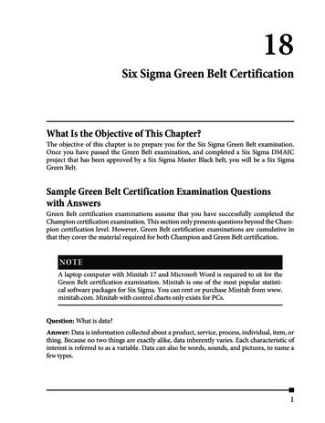
Belt Tension CalculationsThe graph in Figure 6.3 provides a convenient means of estimating the belt tension,Tam , for accelerating the material as it is fed onto the belt.7. Tac — from the resistance generated by conveyor accessoriesConveyor accessories such as trippers, stackers, plows, belt cleaning equipment,and skirtboards usually add to the effective tension, Te . The additional belt tensionrequirements may come from frictional losses caused by the accessory. If the accessory lifts the conveyed material a force will be added to belt tension.Ttr — from trippers and stackersTo use this chart: Enter chart at belt velocity and read Tam per 1,000 tph. Again enter chart at material velocity in direction of belt travel and read Tam per1,000 tph. This may be positive, zero, or negative. Subtract the second Tam reading from the first Tam reading and convert the differencefrom 1,000 tph to the value for the actual tonnage. This will be the Tam desired, lbs.Figure 6.3. Effective tension required to accelerate material as it is fed onto a beltconveyor.The additional belt pull to flex the belt over the pulleys and rotate the pulleys intheir bearings can be calculated from Table 6-5 or Tables C-l and C-2.The force needed to lift the material over the unit can be calculated from the formula, Tm H x Wm lbs.Frictional resistance of the idlers, belt, and material should be included with thatof the rest of the conveyor.99
Belt Tension, Power, and Drive EngineeringTpl — from frictional resistance of plowsThe use of a plow on a conveyor will require additional belt tension to overcomeboth the plowing and frictional resistances developed.While a flat belt conveyor may be fitted with a number of plows to dischargematerial at desired locations, seldom is more than one plow in use at one time on onerun of the belt conveyor. However, when proportioning plows are used — with eachplow taking a fraction of the load from the belt — two or even three separate plowsmay be simultaneously in contact with the carrying run of the belt.To approximate the amount of additional belt pull that normally will be requiredby well-adjusted, rubber-shod plows, the values given in Table 6-6 can be used.Table 6-6. Discharge plow allowance.Type of PlowAdditional Belt Pull per Plow,at Belt Line(lbs/in belt width)Full V or single slant plow, removing all materialfrom belt5.0Partial V or single slant plow, removing half material from belt3.0Tbc — from belt-cleaning devicesBelt scraper cleaning devices add directly to the belt pull. The additional belt pullrequired for belt cleaning devices can vary from 2 to 14 lbs/in. width of scraper bladecontact. This wide variance is due to the different types of cleaning blades and singlecleaner system vs. multiple cleaner systems that are available. In lieu of data on specific cleaning system being used, use 5 lbs/in. width of scraper blade contact for eachblade or scraper device in contact with the belt.Rotary brushes and similar rotating cleaning devices do not impose appreciablebelt pull, if independently driven a
89 Belt Tension Calculations W b weight of belt in pounds per foot of belt length. When the exact weight of the belt is not known, use average estimated belt weight (see Table 6-1) W m weight of material, lbs per foot of belt length: Three multiplying factors, K t , K x , and K y , are used in calculations of three of the components of the effective belt tension, T