Transcription
Melexis USB LIN masterVersion 2.0Melexis USB LIN MasterVersion 2.0 revision Fast LoaderDocumentationFor Melexis USB LIN master used in demo setups anddevelopment kitsRev. 004Page 1 of 13Application noteOct/06
Melexis USB LIN masterVersion 2.0Table of Contents1. General description . 32. Hardware . 33. Software. 33.1. Installation of the LIN master . 43.1.1. Installing the USB driver. 43.1.2. Installing the LIN master application software . 63.2. LIN commander . 73.2.1. Lin Schedules and LIN Sequences . 93.2.2. Log window . 93.2.3. Start working with the LIN commander . 93.2.4. Reprogramming of Melexis modules using the LIN Master . 104. Appendix A: Possible LIN baudrates. 115. References . 136. Disclaimer . 13Rev. 004Page 2 of 13Application noteOct/06
Melexis USB LIN masterVersion 2.01. General descriptionThe Melexis USB LIN master can be used for all applications requiring a LIN master. It is designed tosupport the automatic configuration algorithms as they are defined by the LIN consortium. The MelexisLin master is fully configurable by software through the USB port and supports all practical baud rateson the LIN bus.This user manual describes the LIN master revision 2 (Fast loader). This LIN master is backwardscompatible with LIN master revision 1.2. HardwareThe LIN master consists of a microcontroller connected to the TH8061 physical layer interface ofMelexis. It can be connected to the PC using the USB port. The LIN bus and power supply can beconnected through connectors at one side of the device. There are 5 control LEDs:1. PC connected: indicates that the PC is connected and the USB link is active.2. PC communication: indicates that there is communication between the PC and the master.3. M2S: indicates that a message with data field send by the master is travelling over the bus.4. S2M: indicates that a message with data field send by a slave is travelling over the bus.5. Vbus: indicates that the LIN bus is powered and that messages can be send.The internal microcontroller and LEDs are powered by the USB bus. When the USB plug is connected,communication with the microcontroller over the USB line is possible. The LIN bus itself is notpowered by the USB interface. Therefore an extra power supply has to be foreseen. The LIN busvoltage will be 1 diode voltage lower than the external power supply. As soon as the power supply isabove 8V, the green LED will be on. When the LIN voltage is lower than 7V, the internalmicrocontroller will still send the requested LIN message to the physical layer. Because of the fact thatthe physical layer is not powered according to the LIN specifications, the signals on the LIN bus willnot be valid. But the fact that the LIN voltage is out of spec does not block the functionality of themaster. Even when the LIN voltage is out of spec, the microcontroller drives the physical interface ofthe LIN bus.After connecting the USB cable, the microcontroller is powered. All 5 LEDs will be on forapproximately 10 seconds. After those 10 seconds, some of the LEDs will flash and only the PCconnected LED will be on. If the external power is connected, the green Vbus LED will be on too. Fromnow on, all LEDs will react on PC and LIN messages.Pinout of the different connectors:- Red banana connector battery voltage 12V typical.- Black banana connector ground- Yellow banana connector LIN bus3. SoftwareThis chapter describes the necessary steps to install the device drivers and all the software necessaryto communicate with the LIN master.All software is written for Windows XP Pro. It might be possible that is it working under other versionsof windows, but this cannot be guaranteed.Rev. 004Page 3 of 13Application noteOct/06
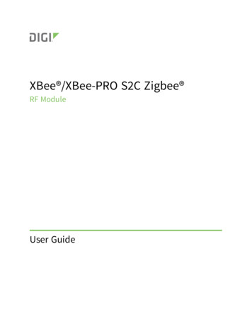
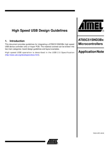
Melexis USB LIN masterVersion 2.03.1. Installation of the LIN masterThis chapter describes the necessary installations to do to be able to work with the LIN master.Note that both software and device drivers installations are required in order to work with thedevice and must be done before the first time you connect the LIN Master to the PC. Also, to beable to successfully accomplish these installations you need administrative rights on the PC.3.1.1. Installing the USB driverInsert the CD into your PC1. An autorun popup screen will appear2. Click on the “Install USB driver” button to start the installation3. A welcome window will appear. Click “Next” button to continue4. You’ll see a window with the license agreement and a few installation windows popping up.Accept the license and ignore all the windows.Rev. 004Page 4 of 13Application noteOct/06
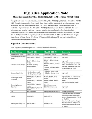
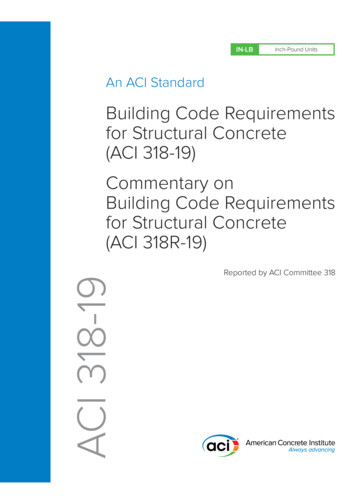
Melexis USB LIN masterVersion 2.05. At the end, this window tells that the installation is done successfullyThe correct drivers are installed. From now on, the LIN master can be accessed via a virtual COMport. Note that the first time the device is connected to a particular USB port, an automatic virtual COMport installation is performed and a unique COM port number is assigned. Check the device managerof Windows XP to get the number of the COM port the LIN master is connected to (start- settings control panel- system- hardware- device manager- Ports (COM & LPT)).Rev. 004Page 5 of 13Application noteOct/06
Melexis USB LIN masterVersion 2.03.1.2. Installing the LIN master application softwareAfter installing the USB drivers, the software to work with the LIN master have to be installed. Thisinstallation is done automatically.Insert the CD into your PC1. An autorun popup screen will appear2. Click on the Install LinMaster button to start the installation3. You’ll see a window with the license agreement and a few installation windows popping up.Accept the license and ignore all the windows.4. At the end, this window tells that the installation is done successfullyThe LIN master is now ready to use.LIN Master can be used through two applications – LIN commander which is described below and theuser interface module for MPT application which is documented separately in LinMasterUI.pdf.For those, who want to implement their own application, we provide a library along with documentation(LIN PSF Object Model.pdf) and examples in LabView and MS Excel – all delivered on the CD.Rev. 004Page 6 of 13Application noteOct/06
Melexis USB LIN masterVersion 2.03.2. LIN commanderThe LIN master is delivered with a sample interface program that can be used to debug the bus whendeveloping an application. This program is called the ‘LIN commander’ and a screenshot of it isdisplayed in Figure 1.The configuration of the LIN messages is done by a LIN-file. This text file describes the LIN messagesthat can be sent over the bus. Hereafter, the syntax of such a LIN file is given together with anexample:- Comments start with an asterisk (*). The comment symbol should be placed in the beginning ofa line. The whole line is ignored.- Empty lines are ignored- The END keyword indicated the end of the lin file. This keyword must be present, otherwise thefile is ignored. Everything that is written after this end keyword is ignored.- The complete syntax is case insensitive.- The following keywords are defined:o END: indicate the end of the fileo LINBAUDRATE : defines the LIN baudrate on the bus. It should be written in thebeginning of the fileo SCHEDULENAME : defines the name of the schedule.o M2S: defines a master to slave message, the master sends the header as well as thedata bytes.o S2M: defines a slave to master message, the master sends the header of themessage, and the slave the data bytes.o WKU: defines a wake up pulse.o CK13: defines a checksum according to LIN spec 1.3o CK20: defines the enhanced checksum of the LIN 2.0 version- A description of a LIN message consists of two parts, separated by a colon (:)o name of the message: can be any possible string as long as it does not contain acolon.o body of the message.- The body of the message consists out of 4 parts each separated by a comma (,)o message type:1. M2S for a master to slave message: the master sends the header, data bytesand checksum.2. S2M for a slave to master message: the master sends the header and theslave the data bytes and the checksum3. WKU for a wake up pulse. In case of a wake up pulse, not other parametersare necessary.o LIN ID: the LIN ID of the message, always send by the mastero In case of a master to slave message, all the data bytes to be send by the masterIn case of a slave to master message, the number of data bytes that the slave shouldreceiveo A checksum type1. CK13 for checksum according to LIN spec. 1.32. CK20 for an enhanced checksum according to LIN spec 2.0- Multiple messages can be concatenated into one message string. Each message has to beseparated by a semi colon. This can be done to send multiple messages in the same time slot.- All numbers can be decimal or hexadecimal numbers. Hexadecimal numbers are preceded by a ******************************************MELEXIS LIN ****************************************Rev. 004Page 7 of 13Application noteOct/06
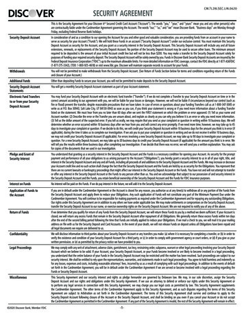
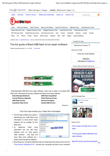
Melexis USB LIN masterVersion 2.0* Example*--------LINBAUDRATE 19200SCHEDULENAME example* a LIN sequence with one M2S LIN messageM2S: M2S, 25, aa, 23, 0a, 04, CK13;* a LIN sequence with one S2M LIN messageS2M: S2M, 26, 04;* a LIN sequence grouping 2 LIN messages, one M2S and one S2M message.M2S S2M: M2S, 25, 01, 02, 0a, 04, Ck20; S2M, 26, 04, CK13;ENDFigure 1: Screenshot of the LIN commander1. Buttons to load the LIN files (schedules and sequences), (dis)connect the LIN master2. The baud rate that is initialized in the LIN file and the real baudrate on the LIN bus3. List of all configured LIN messages4. The LIN message that will be send5. The ‘Once’ and ’Repeat’ buttons to send a message once or repeatedly6. The time between 2 LIN messages when send repeatedly7. LIN schedule and sequence windows8. Message log window.Mover over each button to see a small description on what the button does.Take the following steps to work with the commander:- Connect the LIN master via the USB link- Connect a 12V power supply to the red and black banana connector (or the RJ45 cable).- Double click the LIN commander icon on your desktop to start the software.Rev. 004Page 8 of 13Application noteOct/06
Melexis USB LIN masterVersion 2.03.2.1. Lin Schedules and LIN SequencesA LIN file can be interpreted as sequence or as schedule. The difference between them can beexplained by an example.In a system with multiple slaves, each slave has to react on a subset of the LIN messages on the bus.All possible messages on the bus can be described in a LIN sequence. The subset of messages perslave can be described in a schedule.Lin Sequences are loaded in the sequence window, schedules in the schedule window. There canonly be one loaded sequence at the time, while multiple opened schedules are possible. Eachschedule has its name and all the schedules are listed in the ‘Loaded schedules’ list.The syntax for sequences and schedules is the same and so schedules can be loaded into thesequence window and vice versa. The only difference between the two files is the SCHEDULENAME keyword. If this is not present in the lin file that is loaded as schedule, the software automatically addsthe name “anonymous” to the file when saving it.New schedules can be assembled out of a sequence by writing the name of the new schedule in the‘New schedule name’ field in the schedule window and clicking the ‘new’ button. The schedule contentis displayed in the ‘Selected Schedule’ list. By clicking the ‘Add Sequence’ button the selected LINmessage in the sequence is added to the schedule. Deleting a message from the schedule can bedone by selecting the message in the schedule and clicking the ‘delete sequence’ button. Schedulescan be saved and loaded by the ‘Save’ and ‘Load’ buttons. They are deleted from the schedule list byclicking the ‘Delete’ button. This does not delete the schedule from the hard disk.Sending a LIN message in the sequence is done by selecting the message from the message list andclicking the ‘Once’ button. Sending it repeatedly is done by clicking the ‘Repeat’ button. The timeinterval is given in the ‘Delay’ box. The minimal practical delay is 10 ms due to the Windows timingsystem.Sending a schedule is done by selecting it from the ‘Loaded Schedules’ list and clicking the ‘Once’ or‘Repeat’ buttons. All the LIN messages of the schedule are sent. It is
LIN Master can be used through two applications – LIN commander which is described below and the user interface module for MPT application which is documented separately in LinMasterUI.pdf. For those, who want to implement their own application, we provide a library along with documentation (LIN_PSF_Object_Model.pdf) and examples in LabView and MS Excel – all delivered on the CD.