Transcription
An Absorbed Dose to Water Primary Standard for Ir-192BrachytherapybyIslam Mohamed Medhat El GamalA thesis submitted to the Faculty of Graduate and PostdoctoralAffairs in partial fulfillment of the requirements for the degree ofMaster of ScienceinPhysicsOttawa-Carleton Institute for PhysicsDepartment of PhysicsCarleton UniversityOttawa, Ontario 2013, Islam Mohamed Medhat El Gamal
AbstractThe goal of this work was to develop an absorbed dose to water primary standard forIr-192 brachytherapy by using a Fricke dosimeter. The radiation chemical yield (G-value)of the Ferric ions in the Fricke solution was measured at Co-60 and 250 kVp X-ray,yielding 1.610 0.010 μmol J-1 and 1.602 0.009 μmol J-1 respectively. A log-linearinterpolation was conducted based on the two standard beam values to realize theradiation chemical yield at Ir-192 energy of 1.605 0.005 µmol J-1. A PMMA holder wasdeveloped for irradiations using an Ir-192 brachytherapy source and a final uncertainty onthe dose to water at the reference position of 0.7 % was achieved, in agreement with NRCair-kerma based standards at the 2σ level. The largest contributing factor to thisuncertainty was the G-value at 250 kVp X-ray. A reduction in the G-value uncertaintygives the system the potential to provide an even lower uncertainty on the absorbed doseto water at the reference position.ii
AcknowledgementsI would like to thank my supervisor Dr. Malcolm McEwen, Dr. Carl Ross and Dr.Claudiu Cojocaru for their help, guidance, patience and support without which this workwould not have been possible.Also, I would like to thank Brad Downton and Hong Shen for making time and helpingout with the irradiations throughout this work. David Marchington for building theholders and countless other devices used throughout this work. Dr. Ernesto MainegraHing for painstakingly modeling all the experimental setups and doing all the MonteCarlo simulations and Dr. Paul Johns for his patience, encouragement and support.I would also like to thank everybody at the ionizing radiation standards group for alwaysbeing there to help and for making my time at NRC an unforgettable one. I would like tothank Dr. Addass, Dr. Omar and Dr. Samman for pushing me to pursue graduate studies.Finally, I would like to thank my family and friends for their support and encouragementover the past two years.iii
Table of ContentsAbstract . iiAcknowledgements . iiiTable of Contents . ivList of Tables . viList of Figures. viiList of Appendices . ix12Chapter: Introduction . 11.1Brachytherapy. 11.2Brachytherapy Dosimetry . 21.3Dosimetric Alternatives . 81.4Basis of project . 9Chapter: Fricke Dosimetry . 112.12.1.13Introduction . 11Fricke solution preparation . 112.2Reaction mechanism . 132.3Readout procedure . 142.4Dose to Fricke determination . 212.5G-value variation . 222.6Dose to water determination . 262.7Conclusion . 28Chapter: G-value determination . 303.1Introduction . 303.2X-ray experiment setup . 32iv
3.2.143.3X-ray experiment results . 373.4Cobalt-60 experiment setup . 393.5Cobalt 60 experiment results . 423.6Ir-192 G-value interpolation . 443.7Conclusion . 46Chapter: Ir-192 dosimetry: development of experimental setup . 474.1Introduction . 474.2Holder development . 474.3Irradiation setup . 494.4Source positioning . 524.4.14.556PE bag preparation . 33Holder cleaning procedure . 58Conclusion . 60Chapter: Dose to water at the reference position . 625.1Introduction . 625.2Dose to Fricke evaluation . 635.3Experiment setup dose contribution . 635.4Dose to water determination . 655.5Best estimate of standard uncertainty . 66Chapter: Conclusion . 67Appendices . 69Appendix A Cleaning apparatus . 69A.1Pipette Cleaning . 69A.2Holder and bag cleaning apparatus . 73References . 75v
List of TablesTable 1 250 kVp X-ray G-value experimental uncertainties 2012 . 37Table 2 250 kVp X-ray G-value experimental uncertainties 2013 . 38Table 3 Explicit 250 kVp X-ray G-value uncertainty. 38Table 4 Cobalt-60 2012 experiment results . 42Table 5 Cobalt-60 2013 experiment results . 43Table 6 Cobalt-60 2012 G-value determination . 43Table 7 Ion chambers and diode detectors investigated to determine seed centrepositioning. 55Table 8 Final Iridium irradiation optical density results . 62Table 9 Iridium dose to Fricke measurements . 63Table 10 Summary of irradiation setup effect on absorbed dose. 64Table 11 Fricke correction factors for Iridium setup . 64Table 12 Fricke based dose to water determination at the reference position compared toTG-43 . 65Table 13 Uncertainty budget for Fricke based Dw determination . 66vi
List of FiguresFigure 1 Coordinate system used by the TG-43 dosimetry protocol . 3Figure 2 Ir-192 Photon spectrum (CLRP, 2008) . 7Figure 3 Fe3 ion absorption spectrum (McEwen and Ross, 2009) . 15Figure 4 Quartz cuvette and Teflon lid . 19Figure 5 Cary 400 modified sample compartment . 20Figure 6 Sample spectrophotometer report . 23Figure 7 G-value and effective photon energy relationship historical results collected byKlassen (1999) . 25Figure 8 PE bag used to hold Fricke solution . 34Figure 9 X-ray irradiation setup . 35Figure 10 Net optical density results for 2013 250 kVp x-ray irradiations . 36Figure 11 Net optical density results for 2012 250 kVp x-ray irradiations . 36Figure 12 Cobalt-60 G-value experiment setup . 40Figure 13 Net optical density readings for Cobalt-60 G-value experiments irradiated for atarget dose of 11 Gy . 41Figure 14 G-value experiment results compared to historical data collected by (Klassen etal , 1999) . 45Figure 15 Fricke holder prototype attempt at using Austerlitz parafilm sealing method . 48Figure 16 Final holder design showing the sealing apparatus used . 50Figure 17 Holder dimensions . 51Figure 18 Ir-192 irradiation setup . 53Figure 19 Mounted Fricke holder . 54vii
Figure 20 Attempt to determine seed position along the catheter using Gafchromic film 57Figure 21 Attempt to use a camera to determine seed position along the catheter . 57Figure 22 Sample diode scan to find Ir-192 seed center . 59Figure 23 Pipette rinsing apparatus. 71Figure 24 Pipette cleaning apparatus . 72Figure 25 Fricke funnel and nitrogen source . 73Figure 26 Aspirator used in cleaning procedures . 74viii
List of AppendicesAppendices . 69Appendix A Cleaning apparatus . 69A.1Pipette Cleaning . 69A.2Holder and bag cleaning apparatus . 73ix
1 Chapter: Introduction1.1BrachytherapyBrachytherapy is a radiation therapy treatment modality that involves placing aradioactive source within or close to the tumor volume. It provides a therapeutic gainover conventional external beam radiotherapy, EBRT, by lowering the dose delivered tonormal tissue. The reduction in normal tissue dose can be attributed to the radiation nothaving to travel through normal tissue to reach the treatment site as opposed to EBRT.Brachytherapy can be classified as low dose rate, LDR, and high dose rate, HDR,depending on the source used. LDR sources such as Iodine-125 or Palladium-103 areusually implanted surgically into the treatment volume, the procedure is less invasivethan surgery but involves dose to clinical staff and issues regarding source migrationwithin the patient. HDR sources such as Iridium-192 are delivered for a predeterminedamount of time to the treatment volume, via a catheter, using an after-loader. HDRbrachytherapy is often used as a boost with EBRT and an adequate fractionation regimecan allow it to replace some LDR implants.The development of after-loading technology has increased the number of patientsreceiving brachytherapy. After-loaders store the radioactive sources, also called seeds, ina shielded compartment that reduces the dose to background levels. A catheter is placedin the treatment volume and connected to the after-loader. When the treatment begins the1
after-loader is operated from outside the bunker and the seed is pushed through thecatheter at the end of a steel cable. The after-loader is calibrated to deliver the seed at afixed position within the catheter and can be programmed to withdraw the seed after apreset time. The use of after-loaders has virtually eliminated the dose to clinical staffproviding HDR-brachytherapy. The HDR Ir-192 brachytherapy seeds investigated in thiswork are chiefly applied to the treatment volume using after loader technology allowingthe dose delivered to be controlled by varying the time the seed is allowed to remainwithin the volume, known as the dwell time. Ir-192 is produced through the neutronactivation of naturally abundant Ir-191. The resulting isotope has a complex spectrumwith average decay energy of 0.38 MeV. Ir-192 has a half-life of 73.810 0.019 d andsources typically have a specific activity of 9.22 x 10³ Ci/g (Delacroix et al, 1998).1.2Brachytherapy DosimetryThe absorbed dose is defined as the energy deposited in a medium per unit mass at thepoint of measurement, and is the primary measure of the biological effects of ionizingradiation. The goal of any reference dosimetry protocol is the determination of theabsorbed dose to the patient. However, the practical goal is to determine the absorbeddose to water, Dw. This is typically achieved using a primary standard, a device that givesthe lowest possible uncertainty on the quantity of interest. The primary standard is thenused to calibrate clinical instruments. To date the American Association of Physicists inMedicine, AAPM, task group 43, report (1995) along with its update (2004) forms the2
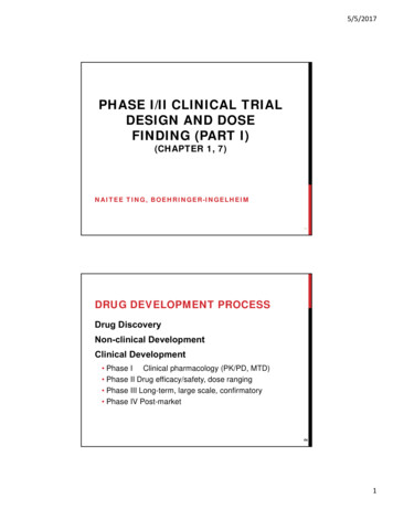
Figure 1 Coordinate system used by the TG-43 dosimetry protocol3
basis of brachytherapy dosimetry in North America. The TG-43 formalism employs thepolar coordinate system used in figure 1, where r denotes the transverse distance from thelongest side of the source whilst θ denotes the polar angle. The dose rate at a point (r,θ) isthus defined for a point source by:̇()̇()( )( ),( )(1.1)where,̇() denotes the dose rate at the reference position taken by convention to be atr 1cm and θ 90 ,( ) is the radial dose function using the point source approximation and represents therelative decrease in dose along r due to the attenuation and scattering of photons bywater,( ) is the 1-D anisotropy function defined for a given r as ̇()̇(), whichrepresents the dose rate, solid angle weighted, averaged over 4 π space divided by thedose rate at the same point on the transverse θ θ0 plane.Only the point source approximation is mentioned for simplicity. It should be noted thatthe quantities in square brackets in equation 1.1, as used clinically, are not measured butcalculated numerically. The dose rate at the reference position, the quantity to bedetermined by a metrology primary standard, is defined in TG-43 as:̇(),(1.2)4
where,SK is the air-kerma strength with units of cGy cm2 h-1, denoted by U, andΛ is the dose rate constant with units of cGy h-1U-1Air-kerma strength is further defined as:̇ ( )where,(1.3)(̇ ) denotes the air-kerma rate in vacuo, the rate of kinetic energy transfer byphotons to electrons at the point of photon interaction per unit mass of air, and d thedistance from the source center to the point at which the air-kerma rate is measured. Thedistance d is chosen such that it is large compared to the source and detector dimensions,usually taken to be on the order of 1 meter, making SK independent of d. SK at Ir-192energy is conventionally determined by taking 7 in air measurements at differentcalibration distances using a secondary standard ion chamber (Goetsch et al, 1991). Theion chamber’s air-kerma calibration coefficients are determined by interpolating using aweighted average the chambers calibration coefficients at Cs-137 and 250 kVp x-rayenergies (DeWerd et al, 2011).Since the air-kerma rate in vacuo is the desired quantity, the measured value has to becorrected for any attenuating effects of air and photon scattering.in equation 1.3 isintended to be an energy cut-off value to exclude the contributions to the air-kermastrength from low energy contaminant photons which only contribute to the dose atdistances of less than 0.1 cm in tissue. The importance of an energy cut-off is greatest forlow energy photon sources and is typically on the order of 5 keV (Rivard et al, 2004).5
Using the 7 distance method described above, uncertainties on SK on the order of 3 % aretypical on end user well chambers (Stump et al, 2001). More recently a comparisonbetween well chambers calibrated at the National Institute of Standards and Technology,NIST, and the National Physics Laboratory, NPL, showed a 2.6 % difference in the doserates measured for the same source (Rasmussen et al, 2011).6
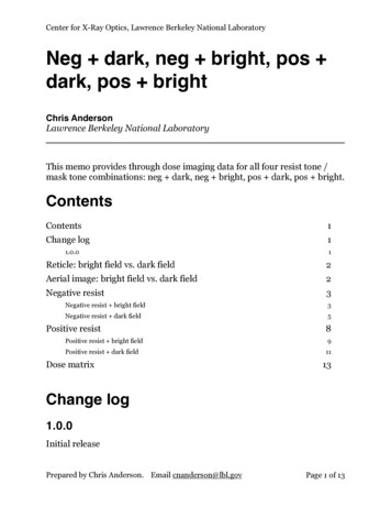
Figure 2 Ir-192 Photon spectrum (CLRP, 2008)where, R denotes the total energy of photons escaping the sourceencapsulation and E the photon energy.7
The dose rate constant, as defined in equation 1.2, depends on the type of radionuclide,the source encapsulation design and composition. Unlike some low energy sources suchas I-125 where the dose rate constant is determined as an average of Monte Carlo andexperimental values, at Ir-192 energies the present determination is entirely Monte Carlobased. The reliance on Monte Carlo is attributed to conventional detector radiosensitivity, energy response, positioning uncertainties and volume averaging effects(Perez-Calatayud et al, 2012). The importance of the dose rate constant should behighlighted as it converts the relative TG-43 dose rate distribution into an absolute one.1.3Dosimetric AlternativesReliance on an air-kerma based standard can be attributed to the difficulties associatedwith near field dosimetry. The high dose gradients surrounding a brachytherapy seedrequire a detector with a small active volume and high resolution to provide an acceptabledose non-uniformity correction (Chiu-Tsao et al, 2007). Estimates on the dosimetricuncertainties of Dw for some conventional air-kerma independent methods weresummarized by DeWerd et al (2011) for high energy brachytherapy photon sources, 50keV: Radiochromic Film 10 % Diamond diode and other solid state detectors 15 % Thermoluminescent LiF Dosimeters 6 %8
Research into calorimeter based Ir-192 brachytherapy dosimetry by Sarfehnia et al (2007)has been able to overcome the challenges associated with source self-heating, heat lossand positioning uncertainty. The parallel plate calorimeter developed has the potential fora combined Dw uncertainty of less than 5 %, with similar results being achieved inEuropean standards labs using graphite calorimeters (Selbach, 2012) and is thus far themost promising air-kerma independent method for the determination of Dw.1.4Basis of projectBy developing an air-kerma independent system to determine Dw at the reference positiondirectly the same TG-43 formalism may be maintained with a reduced uncertainty on Dw.This will in part be due to not having to rely on a Monte Carlo determination of the doserate constant which has been shown to be sensitive to voxel size effects, reaction crosssections and source design (Taylor, 2008).Ideally, as recommended by the TG-43 update (2004), a detector should: Have a small active volume Well characterized energy response Sufficient precision such that at 1σ type A uncertainty should be less than 5%and type B uncertainty should be less than 7% on DwThis work shows that a Fricke based dosimeter satisfies all these requirements allowingfor an air-kerma independent method for the determination of Dw for an HDR Ir-192brachytherapy source with a target standard uncertainty below 1.5 % (k 1). In chapter 2an introduction to Fricke dosimetry is provided whilst chapters 3 and 4 outline thedetermination of the radiation chemical yield of Ferric ions and the development of the9
dosimeter respectively. Chapters 4 and 5 show the calculated dose to water at thereference position and give an overview of the conclusions reached by the project. All ofthe experiments, results and analysis present in this work were conducted by the authorexcept for the radiation transport calculations which were performed by Dr. ErnestoMainegra-Hing of the Canadian ionizing radiation standards laboratory.10
2 Chapter: Fricke Dosimetry2.1IntroductionFricke dosimetry is a chemical dosimetry system developed by Hugo Fricke (Fricke andHart, 1966). Being closely water equivalent and having a high sensitivity in the doserange of interest in radiotherapy has made it the most widely used chemical dosimeter.The main constituents of the dilute aqueous Fricke solution are sulphuric acid and ferrousammonium sulfate. The dosimeter relies on measuring the ferric ions (Fe3 ) producedthrough the oxidation of ferrous ions (Fe2 ) in the solution by water radiolysis products.The yield of ferric ions can consequently be related to the dose imparted to the Frickesolution.2.1.1Fricke solution preparationThe following procedure was used to make Fricke solution in this project following thework of Olszanski et al (2002): A 2 L quartz flask is rinsed 5 times with Millipore water ( ultra-pure water withless than five parts per billion, 5 ppb, of impurities) The flask is filled with 1500 g of Millipore water A beaker is rinsed 5 times with the acid to be used The mass of sulphuric acid to be added ( JT Baker and Company, Philipsburg,Ultrex 2 grade 95.5% acid was used) to the beaker is determined using:11
( )( )( )()(2.1) The acid is dispensed from the beaker to the 2 L quartz flask A Co-60 unit is used to pre-irradiate the water acid mixture to 10 Gy, in order toremove a non-linearity of solution response at low doses due to trace impurities 0.784 g of ferrous ammonium sulfate, 99.997% purity, is added to the flask 0.1169 g of sodium chloride, 100% purity, is added to the flask Millipore water is added until the solution reaches a mass of 2043.4 g to ensurethe correct concentration of reactants is achieved The solution is air saturated by swirling it around within the flask whileperiodically removing the stopper Once air saturated the solution is covered and kept away from all sources of light,to avoid any light induced reactions in the solutionIt should be noted that there are several variations in the literature to the NRC methodof producing Fricke solution, primarily in the acid concentration and the use of NaCl.12
2.2Reaction mechanismOnce the Fricke solution is irradiated, a number of reactions (at least 50 are known), takeplace. The highest yield and hence the most relevant reactions are shown (Jayson et al,1975,Klassen et al, 1999,McEwen and Ross, 2009):H· O2 HO2·(2.2)HO2· Fe2 HO2 Fe3 (2.3)HO2 H H2O2(2.4)H2O2 Fe2 HO Fe3 HO·(2.5)HO· Fe2 HO Fe3 (2.6)H· H2O HO· H2(2.7)These reactions highlight two important features of the Fricke dosimeter: that theoxidation of ferrous ions is due to reactions involving the radiolysis products of water andthat the Ferric ion yield is oxygen dependent, hence the need to air saturate the solution.The oxygen dependence is due to reaction 2.2 being replaced by reaction 2.7 in theabsence of oxygen thus reducing the ferric ion yield. The slowest reaction, 2.5, has a halflife of 14 s meaning that the reactions are expected to come to completion before thereadout procedure can begin (McEwen and Ross, 2009). The ferric ion yield is believedto be stable over the course of several days as demonstrated by the use of Fricke solutionas a mail audit dosimeter in other investigations (McEwen and Ross, 2009).13
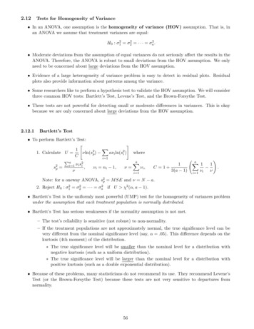
2.3Readout procedureIn order for the Fricke solution to be useful as a dosimeter, the yield of Ferric ions mustbe easily determined. In the past titrimetry was used to determine the ferric ion yield butthe relative speed and automation of modern spectrophotometers has made them thepreferred choice. The creation of ferric ions produces a measurable change in the opticalabsorbance of the Fricke solution which may be measured using a spectrophotometer.Figure 3 shows the absorption spectrum of ferric ions. There are two broad peakscentered at 303 and 224 nm which can be used to measure the change in the opticalabsorption of the Fricke solution. Although the 224 nm peak provides a larger signal formeasurement, the 303 nm peak was used throughout this work. The use of 303 nm isattributed to large variations in the readout signal at 224 nm believed to be due to thepresence of contaminants or the products of chemical reactions involving contaminants.When irradiations are conducted in non-glass vials it appears that the contaminants havea peak close to 224 nm hence explaining the large variations only observed at 224 nm.The optical density is the quantity being measured and is defined as:( ) ,(2.8)where I0 and I denote the incident and transmitted beam intensities respectively. Theabsolute value of I0 is not important since all optical density values used to determinedose are calculated as the difference of two optical density readings with the same I0.14
Figure 3 Fe3 ion absorption spectrum (McEwen and Ross, 2009)15
The following readout procedure was used to determine the change in the optical densityof the Fricke solution: All relevant surfaces are cleaned using Millipore water Tap on Fricke funnel is opened for approximately 2 minutes, to dispose of Frickesolution at the bottom of the funnel that has been exposed to light Plastic tweezers rinsed 5 times with Millipore water Glass dishes are rinsed 5 times with Millipore water 1 mm path length quartz cuvettes ,Figure 4, are removed from Millipore waterfilled beaker using plastic tweezers and placed in glass dishes 3 beakers are rinsed 5 times with Millipore and then filled with Millipore water A beaker is rinsed 5 times with sulphuric acid (JT Baker and Company,Philipsburg, Ultrex 2 grade 95.5%) and then filled with sulphuric acid The aspirator is cleaned with the acid and then rinsed 20 times in each Milliporewater filled beaker The cuvettes are rinsed and dried twice using Millipore water with the aspiratorbeing rinsed 20 times in each Millipore water filled beaker between cuvette rinses A cotton Q-tip applicator is rinsed with Millipore water then used to clean theinside of the cuvette first then the outside transparent windows The cuvette windows are rinsed 10 times with Millipore water and dried usingcompressed nitrogen gas The cuvettes are rinsed and dried 3 times using Millipore water and the aspirator The cuvettes are rinsed using the Fricke solution to be measured, where thesolution is transferred using a pipette (see Appendix A.1) but not dried before
Carlo simulations and Dr. Paul Johns for his patience, encouragement and support. I would also like to thank everybody at the ionizing radiation standards group for always being there to help and for making my time at NRC an unforgettable one. I would like to thank Dr. Addass, Dr. Omar and Dr. Samman for pushing me to pursue graduate studies.