Transcription
Liftline Gas SpringsStandard program, individual gas springsand special functionswww.suspa.com
HeadquartersSubsidiaryAgencySUSPA - Your strong industrial partnerReliability as highest standardFor more than 50 years, SUSPA products have been present in yourdaily life - at home in furniture, refrigerators and washing machines,in means of transport like buses, trains and planes, in modern officefurniture, in leisure and fitness equipment, but also in hospital bedsand operating tables in hospitals and rehab centers.Requirements on quality are increasing in the automotive industry aswell as in other industry sectors. SUSPA certifications according toTS16949 have therefore been an integral part for quite some time.Although you may not be able to see our products, we are alwaysthere – increasing the comfort and safety level for all of you.Major players in the automobile, office furniture, industrial,transportation, appliance, health care, leisure, and gaming industriesdepend on SUSPA as a developmental and systems solution partner.Our engineers and technical sales team will work seamlessly with yourstaff on a wide variety of projects, committed to providing the mosteffective solution for your organization.SUSPA’s worldwide sales and distribution network allows us to alwaysbe in touch with our customers — no matter where they are in theworld! SUSPA has production facilities in Germany, the United States,China, India and the Czech Republic. This worldwide manufacturingcapability gives SUSPA a competitive edge over other gas springmanufacturers.2Effective quality management from purchasing to productionand sales and on to final application secures the worldwide greatreputation and reliability of SUSPA gas springs.We test gas springs 100% according to our internal quality standard.Without any maintenance required, SUSPA gas springs normallyachieve a service life of over 50,000 load cycles.
ContentsDesign, functionality and features4-5SUSPA ordering system6Standard program gas springs (Liftline)7-15Gas springs dampened on extension of the 16-series16-12Ø tube 12 mmØ piston rod 4 mmmax. stroke 150 mmextension force 40-180 N16-1Ø tube 15 mmØ piston rod 6 mmmax. stroke 150 mmextension force 50-420 N16-2Ø tube 18.5 mmØ piston rod 8 mmmax. stroke 250 mmextension force 80-750 N16-4Ø tube 22 mmØ piston rod 10 mmmax. stroke 495 mmextension force 100-1,200 N16-6Ø tube 28 mmØ piston rod 14 mmmax. stroke 500 mmextension force 200-2,000 NEnd fittings78-910-1112-1314-1516-19Clevis, fork heads, ball joints, angle platesAssembly instructionsSpecial functions1920-21Soft-Stop, Positioning gas spring, Space-mat, TouchLiftTechnical advice22Storage, handling, utilization and ine3
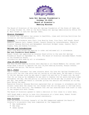
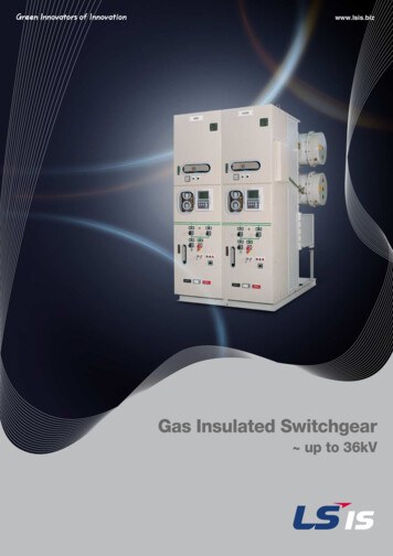
Design and functionality of gas springsHow force and effective cushioningare producedGas springs are hydropneumatic adjustment elements. They consist ofa pressure tube plus piston rod with piston unit. Connecting elementson the pressure tube and the piston rod allow appropriate connectionto your application.If the extension force of the gas spring is greater than the force ofthe counterbalance, the piston rod extends; if the extension force issmaller, it retracts. The speed of the extension is determined by theflow cross section in the damping system.At the core of the SUSPA gas spring is the special seal and guidesystem. This ensures hermetic sealing of the cavity with low friction,even under extreme environmental conditions.In addition to nitrogen, the cavity contains a defined quantity of oilfor lubrication and end position cushioning.The cushioning effect of a gas spring can be determined depending onthe requirements and the task involved.The gas spring is filled with non-toxic nitrogen at high pressures.This produces a charging pressure that in turn exerts an effect onthe cross section of the piston rod, generating the extension force.ClevisPneumatic mediumPressure tubePiston assemblyassemblyPistonHydraulic mediumSealingguidancepackagepackageSealing and guidancePiston rodClevis4
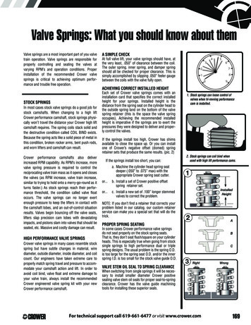
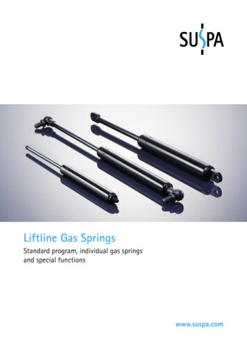
Features of gas springsThe SUSPA standard gas spring (Liftline)at a glanceThe main differences are in the tube and piston rod diameters andthe different extension forces. This way, we can meet your specifictechnical requirements with the optimal gas spring type.Liftline is an excellent gas spring progam offered by SUSPA.Successfully proven in the market for decades and always state-ofthe art through constant innovation. The SUSPA Liftline programincludes five basic types: the types 16-12, 16-1, 16-2, 16-4 and 16-6.TypeØ Tube (mm)Ø Piston rod (mm)Stroke max. (mm)Extension force F1 (N)Page16-1212415040 - 180716-115615050 - 420816-218.5825080 - 7501016-42210495100 - 1,2001216-62814500200 - 2,00014Spring characteristicGas springextendedGas springcompressedCompression forceFRF4F3F2F1Extension forceForce[N]Spring characteristicX F2/F1Stroke[mm]Damping zone55pneumatichydraulicStrokeAs seen in the graphic, the spring characteristic curve shows theforce path of the gas spring over the stroke, from the extended tothe retracted state and back. The spring characteristic illustrates thebalance of power of F2/F1. For the design of gas springs, the force F1 is,in addition to the dimensions, the most important criterion.The force F1 is measured 5 mm before the end of the extensionmovement and thus defines the value of the spring force. The resultingfriction force FR is generated between the lines of force in theinsertion and extension direction. The extension speed is dividedinto two types of dampers: In the case of the standard gas spring,the extension speed is controlled via a pneumatic and hydraulicsection. When installing the gas cylinder with the piston rod pointingdownwards, the piston initially moves through the gas-filled part(pneumatic range), thereafter, through the oil-filled part of thepressure tube (hydraulic area). The piston rod is slowed down bythe oil.If desired, damping can also performed dynamically by applying anaxial groove in the tube, which allows damping independent of thegas spring position.Liftline5
SUSPA ordering system – simple and transparentThe SUSPA part number consists of the technical details of the gas spring describingtype, tube length, piston rod length and end-fittings.Technical DataLength (mm)TypeTube(A-Measure)FittingsTube(Fitting A)Piston rod(B-Measure)Extension forceIf necessary, the extension force F1 may be added to the end ofthe order number in Newton:Order example: 16-12-49-23-AM4-BM4-120N120NExtension force F1(in Newton)Thread-thread gas springsWhen ordering thread-thread gas springs please specify the required end fittings (see pages 16 - 18):Order example: 16-12-89-63-A457-B457-120NA457 B457Tube(End fitting A)Piston rod(End fitting B)You will find our gas spring configurator online at www.suspa.com/uk/configurator6Piston rod(Fitting B)
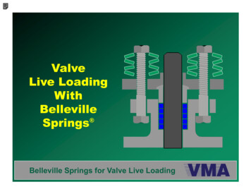
Standard program Liftline gas springs type 16-12Type 16-12 Thread/ThreadØ tube 12 mm, Ø piston rod 4 mm, max. stroke 150 mm, extension force 40-180 N, fitting AM4-BM4Fitting BFitting AL 2Stroke5,50AØ 12Ø 3,80M4BM45,50All dimensions in mm. The standard color of the tube isblack or white aluminium, and the piston rod is black.1. Select length and strokeLength L (mm) 2 Stroke (mm)72209230112132152192232272 *332 *40506080100120150Technical dataPlease select your fittingson pages 16-18!16-12 - 49 - 23 - AM4 - BM416-12 - 59 - 33 - AM4 - BM416-12 16-12 16-12 16-12 16-12 16-12 16-12 -697989109129149179-43536383103123153- AM4 - BM4- AM4 - BM4- AM4 - BM4- AM4 - BM4- AM4 - BM4- AM4 - BM4- AM4 - BM4Gas springs configuratorConstruct your own individual gas spring withour gas spring configurator on our websitewww.suspa.com/uk/configurator* The maximum F1 extension force depends on thecustomer s application.2. Select the desired extension force F1 and fittingsThe extension force F1 can be at least 40N and maximum 180N,the gradation of forces can be selected individually.When ordering please indicate the extension force and the desiredfittings (see pages 16-18) as follows:Order example: 16-12-49-23-AM4-BM4-120NPlease do not hesitate to contact us for individual layouts as forexample a different damping behavior of the gas spring!3. Gas springs without extension force: damper450400Damping force in tension [N]Type 16-12 can be used without extension force as a damper,for example in automobiles, furniture, household appliances orin industrial applications. The damping behavior can be chosenaccording to your needs. The characteristic curve shows the dampingforce depending on the extension speed.Damping behaviour350300250piston Q1200piston Q2150100500020406080100Extension speed [mm/s]Liftline7
Es gilt jeweils der Stand derAlle Rechte vorbehalten gemäß DIN ISO 16016.Verwendung und Vervielfältigung nur bei schriftlicher Zustimmung.angegebenen Norm zumZeitpunkt der Zeichnungserstellung Zuwiderhandlungen verpflichten zum Schadensersatz.Type 16-1 Clevis/Clevis, weldedOnly those standards and their revisions All rights are reserved in accordance with ISO 16016.which where valid before the time ofCopying and use of this document only with authorization.drawing release apply.Non-compliance will result in Suspa seeking damages to cover losses.Standard program Liftline gas springs type 16-1Ø tube 15 mm, Ø piston rod 6 mm, max. stroke 150 mm, extension force 50-420 N, fitting A17-B17All dimensions in mm. The standard color of the gas spring and the piston rod is black.Type 16-1 Ball joint/Ball joint13,50R6136,10 0,3003Fitting A156B17B17 0,30B176,10 0B17B17B17B17B171513-Fitting 0162501201625013A17A17A17A17A17A17A17A17 0,300316-1 - 86 16-1 - 96 16-1 - 96 16-1 - 111 16-1 - 131 16-1 - 168 16-1 - 157.5 16-1 - 189 --6,103number016250070162500851606790110115125154L 2Hub Ordering16-1 - 57 - 26 - A17 - B1716-1 - 78 - 45 - A17 - B173645556080100110120150Technical dataFitting A 0,300Werkstückkanten, wenn nicht anders angegeben/edge of workpiece unless otherwise indidatedDIN ISO 13715, Außenkanten/outside edges -0,2, Innenkanten/inside edges 0,2Es gilt jeweils der Stand derAlle Rechte vorbehalten gemäß DIN ISO 16016.angegebenen Norm zumVerwendung und VervielfältigungZustimmung.v nur bei schriftlicherwxyuZeitpunkt der Zeichnungserstellung DINZuwiderhandlungenverpflichten zum Schadensersatz.ISOgeputzt/cleanedRz 100Only those standards and their revisions1302All rights are reserved in accordancewith ISO 16016.Rz 6,3Rz 1Rz 25which where valid before the time ofCopying and use of this document only with authorization.drawing release apply.Non-compliance will result in Suspa seeking damages to cover losses.Only those standards and their revisions All rights are reserved in accordance with ISO 16016.which where valid before the time ofCopying and use of this document only with authorization.drawing release apply.Non-compliance will result in Suspa seeking damages to cover losses.Es gilt jeweils der Stand derAlle Rechte vorbehalten gemäß DIN ISO 16016.Verwendung und Vervielfältigung nur bei schriftlicher Zustimmung.angegebenen Norm zumZeitpunkt der Zeichnungserstellung Zuwiderhandlungen verpflichten zum )20406,1050Length L(mm) 21061466,10 0,300,R63Fitting BHub505013A,R6,R6B,50StrokeHubR6L 213gem./acc. to VA 04 03 Kontrollmaß / inspection dimension([Ersetzt durch/replaced byMaterialneue ZeichnungWerkstoff) Hilfsmaß / reference dimension] Vorbearbeitungsmaß / pre-work dim.Ø tube 15 mm, Ø piston rod 6 mm, max. stroke 150 mm, extension force 50-420N, fittingA246-B246Ersatz für/replacementforWerkstoff2Drawn 01.01.2012NameBezeichnung/nameABC16-1 Auge/Auge meintoleranz/general tolerancesDIN ISO 2768-mA3Zeichnungsnummer/drawing number16-1 Augen256Fitting BFitting Ay15to VA 04 03gem./acc.gem./acc.to VA 04 03 Kontrollmaßinspection dimension Kontrollmaß/ inspection /dimension([Rz 6,3xwRz 25DateNamevCheckRz 100Drawn 01.01.2012DrawnABCDate 01.01.2012nur in/ÄnderungenÄnderungennur in/withonlyCAD - 3D onlyCheckrevisions withrevisionsCAD - 3Dz1DateÄnderungen nur in/revisions with CAD - 3D onlyRz 1nders angegeben/edge of workpiece unless otherwise indidatedutside edges -0,2, Innenkanten/inside edges 0,2Date0,2Änderungs Nr./ECNWenn nicht anders angegeben/unless otherwise specified Maßstab/scaleMaßangabe in Millimeter/ISO 128-30alte Zeichnungalte ZeichnungyWerkstoWerkstoalte ZeichnungSW13SW13dimensions shown in 25006Zeichnungneue neueZeichnunge indidatedMaterialneue ZeichnungDateErsatz für/replacementforErsatz für/replacementforIndex Nr./ECNÄnderungs Nr./ECNIndex ÄnderungsDateErsetzt durch/replaced byErsatz für/replacement forL 2 IndexM8 M8Ersetzt durch/replacedbyErsetzt durch/replacedby812HubOrderingHub16-1 - 53.5 - 24 - A246 - B24616-1 - 67 - 40 - A246 - B24616-1 - 72.5 - 45 - A246 - B24616-1 - 91 - 65.5 - A246 - B24616-1 - 113 - 84 - A246 - B24616-1 - 117 - 90 - A246 - B24616-1 - 131 - 104 - A246 - B24616-1 - 154 - 124 - A246 - B24616-1 - 161 - 124 - A246 - B24616-1 - 168 - 148 - A246 - B24616-1 - 183.5 - 154 - A246 - B2461/116,50Technical heet16-1 Augen geschwFitting A16,506Zeichnungsnummer/drawing number121:113AA36u16-1 Auge/Auge geschweißtBezeichnung210 10Wenn nicht anders angegeben/unless otherwise specified Maßstab/scaleMaßangabe in Millimeter/ISO 128-30dimensions shown in ral tolerancesDIN ISO 2768-mFitting BDIN ISO1302Es gilt jeweils der Stand derangegebenen Norm zumZeitpunkt der e, Datum, Verteiler/edition, date, copies forNameABC15Only those standards and their revisions All rights are reserved in accordance with ISO 16016.which where valid before the time ofCopying and use of this document only with authorization
We test gas springs 100% according to our internal quality standard. Without any maintenance required, SUSPA gas springs normally achieve a service life of over 50,000 load cycles. Liftline 3 Contents Design, functionality and features 4-5 SUSPA ordering system 6 Standard program gas springs (Liftline) Gas springs dampened on extension of the 16-series 7-15 16-12 Ø tube 12 mm Ø piston rod 4 .