Transcription
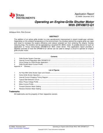
Application ReportSLVA858 – December 2016Operating an Engine-Grille Shutter MotorWith DRV8872-Q1Ishtiaque Amin, Rick DuncanABSTRACTThe addition of an active grille shutter is a key aerodynamic improvement in recent model-year vehicles.Depending on the ambient temperature of the environment, the shutters behind the engine grille can openand close to increase the engine efficiency and reduce turbulent air from entering the engine, therebyreducing drag. The shutters can be operated by a brushed DC (BDC) motor. A suitable device for such anapplication is Texas Instruments' DRV8872-Q1 BDC motor driver. This application report provides adetailed overview of how the DRV8872-Q1 device can be used to design a circuit to operate an enginegrille shutter motor.Contents1Grille Shutter System Overview .2Internal Current Regulation With DRV8872-Q1.3Circuit Design for Grille-Shutter Application .4Grille Shutter Motor-Current Profile .Appendix AGlossary .23357List of Figures1Air Flow With Grille Shutter Open and Closed . 22Active Grille Shutter Operation. 23Internal Current-Chopping Timing Diagram . 34Typical Stall-Detection Circuit . 45Motor Phase-Voltage Profile678.Motor-Current Profile .Forward Direction Motor Stalling .Reverse Direction Motor Stalling .4556TrademarksAll trademarks are the property of their respective owners.SLVA858 – December 2016Submit Documentation FeedbackOperating an Engine-Grille Shutter Motor With DRV8872-Q1Copyright 2016, Texas Instruments Incorporated1
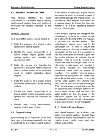
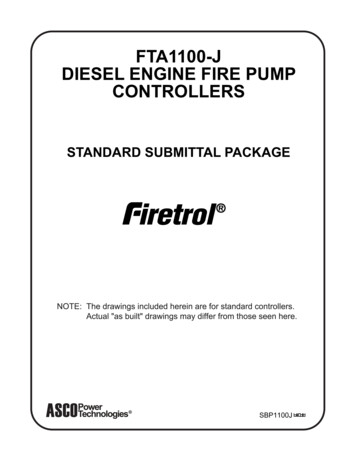
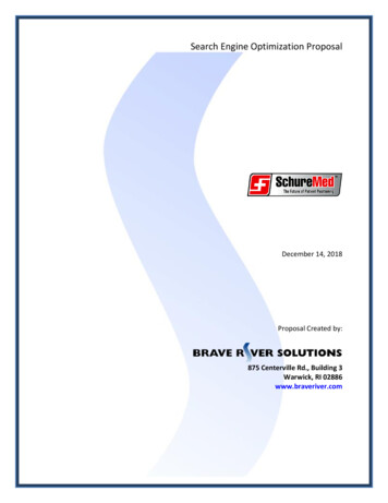
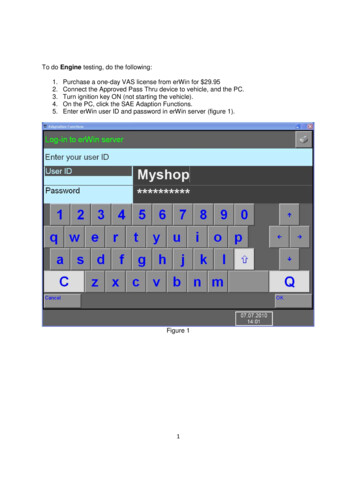
Grille Shutter System Overview1www.ti.comGrille Shutter System OverviewWhen the engine-grille shutters open, air is allowed to flow through the radiator and into the enginecompartment for faster cooling of the engine. But when that cooling air is not needed, the shutters close,as determined by the engine control unit (ECU), which reroutes air around the vehicle creating lessturbulence than what would otherwise exist if the air was to flow through the vehicle. The reducedturbulence lessens the aerodynamic drag by up to 6%, increasing fuel economy and reducing carbondioxide emissions by up to 2%.Figure 1. Air Flow With Grille Shutter Open and ClosedAs an added advantage, the closed shutters also reduce engine warm-up time in cold weather by stoppingair from entering the engine on cold days. This advantage allows the engine to run more efficiently,heating to the optimal operating temperature faster, and warming up the interior of car quicker. Figure 2shows an active grille shutter typically found in most modern vehicles.Figure 2. Active Grille Shutter OperationThe brushed DC motor used to operate the shutters would have a peak current rating of approximately 1A. The DRV8872-Q1 motor driver is a suitable device support this requirement. The device can be used toregulate motor current around 1 A by following the process described in Section 2.2Operating an Engine-Grille Shutter Motor With DRV8872-Q1Copyright 2016, Texas Instruments IncorporatedSLVA858 – December 2016Submit Documentation Feedback
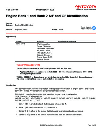
Internal Current Regulation With DRV8872-Q1www.ti.com2Internal Current Regulation With DRV8872-Q1The DRV8872-Q1 device features current regulation that restricts the motor current to a preset maximum.This restriction is achieved by appropriately sizing an external sense resistor (RSENSE) on the ISEN pin.Use Equation 1 to calculate the current trip level (ITRIP).VtripITRIP (A)RSENSE(1)The voltage trip level (Vtrip) for the device is internally set to 0.35 V (nominal). Select the current-choppinglimit of 900 mA which is close to what a grille-shutter BDC motor would receive for peak current.Vtrip 0.35 VRSENSE0.388 :ITRIP0.9 A(2)Use Equation 3 to calculate the power dissipation (PD) for the RSENSE resistor.I2RPD (RSENSE )0.92u 0.3880.315 W(3)Therefore, a resistor with these specifications should be appropriate for regulating current in thisapplication. An industry-standard part could be a 0.39-Ω, ½ W resistor in a1206 or larger package.When the ITRIP threshold is reached the device stops driving the motor and enforce slow decay through thelow-side MOSFETs. The motor will be in slow decay for typically 25 µs (tOFF time) and, after tOFF hasexpired, the outputs will be re-enabled to operate the motor for a drive time (t(DRIVE)) until the ITRIP thresholdis reached. Figure 3 shows the timing diagram for this operation.Motor Current (A)ITRIPDriveBrake and Slow DecayDriveBrake and Slow Decayt(DRIVE)tOFFt(DRIVE)tOFFFigure 3. Internal Current-Chopping Timing DiagramThe drive time of the motor (t(DRIVE)) primarily depends on the supply voltage, motor inductance, and theback-EMF generated by the motor. For more details about the device, refer to DRV8872-Q1 Automotive3.6-A Brushed DC Motor Driver With Fault Reporting (SLIS175).3Circuit Design for Grille-Shutter ApplicationThe block diagram in Figure 4 shows a basic circuit that can be implemented to operate the grille shutters.The DRV8872-Q1 device receives command from the microcontroller unit (MCU) through the IN1 and IN2lines and drives the BDC motor. The value of the RSENSE resistor, connected to the ISEN pin, is selectedbased on the calculations in Section 2. The Zener diode is optional but recommended to clamp the nodeto 3.6 V.If the source of the power supply is the vehicle battery, instances of load dump could occur for which theZener diode will be required, especially if the MCU has 3.3-V rated digital I/O pins. Without the Zenerdiode, the MCU I/O pin can receive a higher voltage that can potentially damage the MCU.NOTE: The resistor values for R1 through R4, in Figure 4, have been selected for a regulated powersupply (VBATT) of 13.5 V.The phase voltages of the motor will be approximately 0 V and battery voltage depending on whichdirection the motor is rotating. The R2 resistor is in parallel with the R3 and R4 resistors so the voltagebetween at the node between R1 and R2 becomes 4.5 V. This voltage gets further scaled down by theresistor divider network of R3 and R4 to bring the nSTALL node voltage to 3.15 V, as shown byEquation 4.SLVA858 – December 2016Submit Documentation FeedbackOperating an Engine-Grille Shutter Motor With DRV8872-Q1Copyright 2016, Texas Instruments Incorporated3
Circuit Design for Grille-Shutter ApplicationVnSTALLwww.ti.com§R2 R3 R4@ ªR1 R2 R3 R4@ · u 13.5 V u § R3 ·º R3 R4 ¹¼¹3.15 V(4)If the power supply is significantly higher than 12 V, for example 24 V (which is within the operating supplyrange of the device), the voltage at the nSTALL node, without the Zener diode, becomes 5.6 V. Such ahigh voltage can damage the MCU and, therefore, the resistors, R1–R4, should be sized appropriately tomeet the maximum allowable voltage at the I/O pin of the MCU, in addition to placing the Zener diode.VBATTVCCIN1R110 kIN2R43kMMCUnSTALLDRV8872-Q1nFAULTnSTALLR37kR210 k47 pF3.6 VISENRSENSE § 0.39, ½WCopyright 2016, Texas Instruments IncorporatedFigure 4. Typical Stall-Detection CircuitWhen the motor is running, the voltage at each motor phase is monitored by the MCU, after some signalconditioning, for a motor stall condition. The voltage profile at the nSTALL node will be similar to theprofile in Figure 5.3.6 V(maximum)Motor stalled(DRV8872-Q1 enters current regulation)tRUNnSTALL0VFigure 5. Motor Phase-Voltage ProfileWhen the MCU identifies the voltage profile at the nSTALL node to be similar to the highlighted portion inFigure 5, the motor has stalled. One way to identify the voltage profile is to trigger an interrupt in the MCUat the first falling edge of the nSTALL node after the motor has been running for the tRUN time. The MCUcan then measure the time interval between the first falling edge to the next rising edge and compare it tothe tOFF time of the device. If this time interval is less than tOFF equal to 25 µs (with about 10% tolerance), itcan be concluded that the motor has stalled. At this point, the MCU must shut off or change the rotationaldirection of the motor.The current profile of the motor moving in a given direction (for example, in reverse drive) during thisprocess will look similar to profile in Figure 6. For motor rotation in the opposite direction (for example,forward drive) the profile is inverted. Section 4 includes application graphs for motor motion in bothclockwise and counter-clockwise directions.4Operating an Engine-Grille Shutter Motor With DRV8872-Q1Copyright 2016, Texas Instruments IncorporatedSLVA858 – December 2016Submit Documentation Feedback
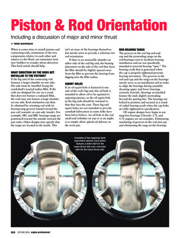
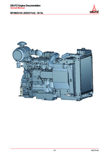
Grille Shutter Motor-Current Profilewww.ti.comMotor stalls at 1 AMotor startsrunningMotor runs normally0AFigure 6. Motor-Current ProfileAn inrush of current occurs initially to start the motor. Following that inrush, the current flowing through themotor windings decays to an rms value while the grille shutter is in motion. When the shutters arecompletely open or closed, the motor stalls at a peak current of approximately 1 A.4Grille Shutter Motor-Current ProfileFigure 7 shows current flowing through the motor in forward drive, and the voltage profile at the nSTALLnode. The steady-state DC current is approximately 375 mA. As the current flowing through the motorincreases above 800 mA, the device starts to perform current regulation. The stall-detection circuit togglesbetween logic levels 0 and 1 at the nSTALL node, indicating to the MCU that the motor has stalled. Thezoomed-in plots show the motor-current profile during start-up and stall.Figure 7. Forward Direction Motor StallingSLVA858 – December 2016Submit Documentation FeedbackOperating an Engine-Grille Shutter Motor With DRV8872-Q1Copyright 2016, Texas Instruments Incorporated5
Grille Shutter Motor-Current Profilewww.ti.comFigure 8 shows current flowing through the motor in reverse drive, and the voltage profile at the nSTALLnode. The peak current is limited by the RSENSE resistor to approximately 800 mA.Figure 8. Reverse Direction Motor StallingBased on these plots, the DRV8872-Q1 device is concluded to be able to drive the BDC motor for anengine-grille shutter. The stall-detection circuit (Figure 4) also provides accurate information to the hostMCU regarding motor stall which prevents the device from over driving the motor.6Operating an Engine-Grille Shutter Motor With DRV8872-Q1Copyright 2016, Texas Instruments IncorporatedSLVA858 – December 2016Submit Documentation Feedback
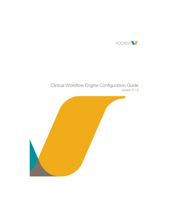
Appendix ASLVA858 – December 2016GlossaryA.1Nomenclature Used in this DocumentThe following acronyms and initialisms are used in ths document:BDC — Brushed DCECU — Engine control unitIC — Integrated circuitMCU — Microcontroller unitMOSFET — Metal-oxide semiconductor field-effect transistorOCP — Overcurrent protectionPWM— Pulse width modulationFor a more comprehensive list of terms, acronyms, and definitions, refer to the TI Glossary (SLYZ022).SLVA858 – December 2016Submit Documentation FeedbackOperating an Engine-Grille Shutter Motor With DRV8872-Q1Copyright 2016, Texas Instruments Incorporated7
IMPORTANT NOTICETexas Instruments Incorporated and its subsidiaries (TI) reserve the right to make corrections, enhancements, improvements and otherchanges to its semiconductor products and services per JESD46, latest issue, and to discontinue any product or service per JESD48, latestissue. Buyers should obtain the latest relevant information before placing orders and should verify that such information is current andcomplete. All semiconductor products (also referred to herein as “components”) are sold subject to TI’s terms and conditions of salesupplied at the time of order acknowledgment.TI warrants performance of its components to the specifications applicable at the time of sale, in accordance with the warranty in TI’s termsand conditions of sale of semiconductor products. Testing and other quality control techniques are used to the extent TI deems necessaryto support this warranty. Except where mandated by applicable law, testing of all parameters of each component is not necessarilyperformed.TI assumes no liability for applications assistance or the design of Buyers’ products. Buyers are responsible for their products andapplications using TI components. To minimize the risks associated with Buyers’ products and applications, Buyers should provideadequate design and operating safeguards.TI does not warrant or represent that any license, either express or implied, is granted under any patent right, copyright, mask work right, orother intellectual property right relating to any combination, machine, or process in which TI components or services are used. Informationpublished by TI regarding third-party products or services does not constitute a license to use such products or services or a warranty orendorsement thereof. Use of such information may require a license from a third party under the patents or other intellectual property of thethird p
For a more comprehensive list of terms, acronyms, and definitions, refer to the TI Glossary (SLYZ022). IMPORTANT NOTICE Texas Instruments Incorporated and its subsidiaries (TI) reserve the right to make corrections, enhancements, improvements and other changes to its semiconductor products and services per JESD46, latest issue, and to discontinue any product or service per JESD48, latest