Transcription
Run-around coil ventilation heat recovery system: A comparative studybetween different system configurationsJörgen Wallin*, Hatef Madani, Joachim ClaessonDepartment of Energy Technology, Division of Applied Thermodynamics and RefrigerationRoyal Institute of Technology, SE-100 44 Stockholm, Sweden* Phone: 46 (0)8 790 86 53, Fax: 46 (0)8 20 30 07, Email: jorgen.wallin@energy.kth.seAbstract:The energy performance of buildings with considerable annual heat load is dependent on theventilation air change rates (ACH). Buildings utilized for commercial use often have highACH and therefore high annual heat load. In order for these buildings to have a reasonableenergy performance a heat recovery system is often used to recover heat from the extractionair to the makeup air. There are different variations of these systems; one that is frequentlyused in Sweden is a run around coil heat recovery system.The present paper summarizes the findings from the previous studies, and presents acomparative study, for three different cases; the traditional run-around coil heat recoverysystem; with a three stage on/off controlled heat pump retrofitted into the system; and with avariable capacity heat pump retrofitted into the system.Annual modeling shows that by retrofitting a well-designed 3 stage heat pump to the systemthe annual heat recovery rate for the Stockholm Case can be increased from 47 % to 65 %.For the retrofitted variable capacity heat pump the numbers for the Stockholm Case is animprovement of annual heat recovery from 47 % to 66 %.The modeling also shows that a well designed variable heat pump can cover 81 % of theventilation heating demand and a well designed multi stage heat pump 77 % of the demand.Keywords Run-around coil, ventilation heat recovery, performance factors, retrofitted heatpump.1ICAE 2010 – International conference on Applied energy – Singapore 21‐23 April 2010
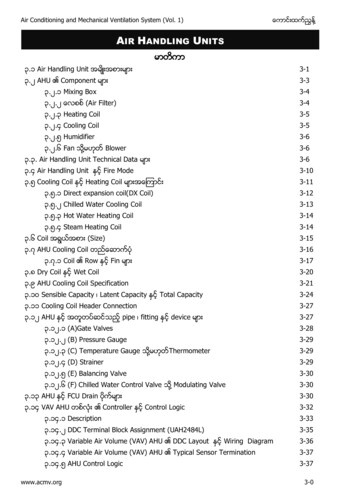
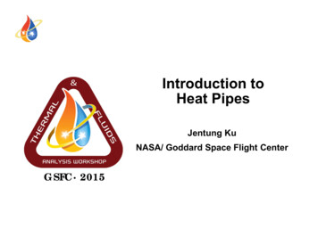
1. IntroductionThe energy performance of buildings with considerable annual heat load is dependent on theventilation air change rates (ACH). Buildings utilized for professional use often have highACH and therefore high annual heat load. In order for these buildings to have a reasonableenergy performance a heat recovery system is often used to recover heat from the extractionair to the makeup air. There are different variations of these systems; one that is frequentlyused in Sweden is a run around coil heat recovery system.A run-around coil heat recovery system is often used in buildings where the extraction aircontains volatile substances that can contaminate the supply air. Hospital buildings are oneexample of a building type that matches this criterion; another one is buildings that containprocessing industry.Previous studies [1, 2, 3, 4, and 5] have looked into the important factors that influence theperformance of ventilation heat recovery system with a run around coil. Several factors havebeen identified in the previous studies; of special interest are the brine flow rate and theglycol concentration of the brine. Another study [6] has investigated the possibility toincrease the rate of recovery by retrofitting a multi stage heat pump to a run around coilrecovery system. The conclusion for the retrofitted heat pump study is that there is apotential for improved energy performance if the sizing of the heat pump system is correct.In the Madani et. al. [7] study the performance of a heat recovery system using variablespeed heat pump together with the run around coil was modeled and analyzed.The present paper summarizes the findings from the previous studies, and presents acomparative study, for three different cases; the traditional run-around coil heat recoverysystem; with a three stage on/off controlled heat pump retrofitted into the system; and with avariable capacity heat pump retrofitted into the system.1.1 The different system setups – Run around coilA run-around coil heat recovery systemconsists of at least two coiled heatexchangers. The coils are connected viapipes to a loop in which a fluid flows. Thefluid is usually a mix of water and an antifreeze fluid. Heat is “moved” from the hotside (extraction/exhaust air) to the coldside (supply air) via the brine fluid. It isalso possible to recover cooling energyduring the warm days. The flow rate to thesupply heat exchanger is usually controlled Fig. 1. Scheme of a run around coil heat recoveryby a three way valve or by frequencycontrolling the pump. The flow rate is controlled so that the temperature on the supply airdoes not exceed the desired value. The size of the heat exchangers is traditionally designed torecover around 50 % of the heat when the ambient temperature is 0 C.2ICAE 2010 – International conference on Applied energy – Singapore 21‐23 April 2010
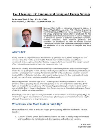
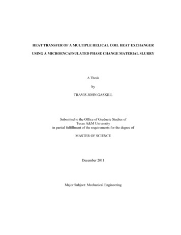
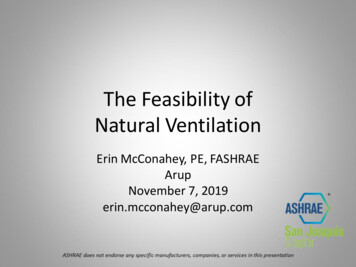
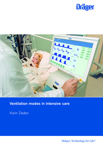
1.2 The different system setups – Run around coil and retrofitted heat pumpA heat pump is retrofitted to the existing run around coil system, as shown in fig. 2.Depending on the ambient temperature, the heat recovery system can be switched from runaround coil to the heat pump unit and vice versa. The different routes of the brine depend onthe operation mode, and are denoted 1 and 2 in the scheme.Fig. 2. Scheme of a run around coil heat recovery when the heat pump unit is retrofittedTwo different heat pumps have been evaluated, in the first case a 3 stage on/off controlledheat pump unit was evaluated, secondly the system performance was evaluated using avariable capacity heat pump. With the heat pump retrofitted it is possible to lower thetemperature of the exhaust air below the ambient temperature. This fact can be used toachieve a greater recovery rate than the traditional run around coil system.2. ResultsIn a previous study, Madani et. al [6] investigated the efficiency for an existing medium sizedrun around coil heat ventilation heat recovery system; air flow rate around 6-7 kg/s.Simulations pointed at a recovery rate of 47% over one full year. This model was then used tosimulate the system performance with different retrofitted heat pump units. Fig. 3 shows acomparison between the annual performances of the three different system setups in twoEuropean locations.3ICAE 2010 – International conference on Applied energy – Singapore 21‐23 April 2010
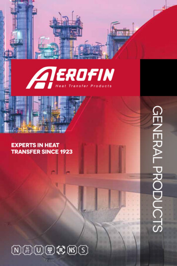
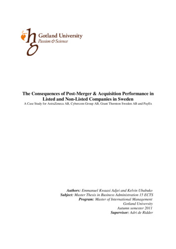
Heat recovery, Stockholm caseHeat recovery, Berlin %0%Retrofittedvariablecapacity HPRetrofittedRetrofitted 3 Run around coilvariable capacity stage on/off HPHPRetrofitted 3 Run around coilstage on/off HPFig. 3. Annual heat recovery for different system setups in Stockholm, Sweden and Berlin, GermanyFig. 3. shows that the heat recovery for the system with a 3 stage heat pump and the systemwith the variable capacity heat pump more or less have same percentile recovery for theStockholm Case, For Berlin Case the performance of the retrofitted 3 stage heat pump is notas efficient as the variable capacity heat pump. The reason for this is that the 3 stage heatpump is designed for the Stockholm case. The sizing of the heat pump unit is important tohave a high system performance; this is especially true for the 3 stage pump [6].Another way of looking at the system is to evaluate the total annual heating supplied by theheat pump. Fig. 4. shows how much of the total heating demand of the air handling unit that iscovered by the run around and the heat pumps.Degree of coverage for the heat pump cases is how much energy that is supplied to the airgoing to the building, i.e. total recovery energy supplied to the compressor divided by thetotal demand of the air handling unit.Degree of coverage,Stockholm caseDegree of coverage,Berlin 0%40%30%20%10%0%Retrofittedvariablecapacity HPRetrofitted 3stage on/offHPRun aroundcoilRetrofitted Retrofitted 3 Run aroundvariablestage on/offcoilcapacity HPHPFig. 4. Annual degree of coverage for different system setups in Stockholm, Sweden and Berlin, Germany4ICAE 2010 – International conference on Applied energy – Singapore 21‐23 April 2010
You could also argue that the exhaust air temperature is a measure on how efficient the heatrecovery system is, i.e. if the exhaust air temperature is the same as the ambient temperaturethe heat recovery would be 100 %. In Fig. 5 the exhaust air temperature is plotted togetherwith the ambient temperature for the different system setups for January.Exhaust air‐ and ambient air temperature for different system setups15 C10 CTemperature5 C0 C0.0100.0200.0300.0400.0500.0600.0700.0‐5 C‐10 C‐15 C‐20 CJanuaryRun around coil3 stage heat pumpVariable capacity heat pumpAmbient temperatureFig. 5. Exhaust air- and ambient temperatures for different heat recovery systems in JanuaryFrom Fig. 5. the improvement of the heat recovery is visible. It is also visible that there is anambient temperature when the run around coil system is as efficient as the heat pump systems.For the 3 stage heat pump system this is around -15 C, for the variable capacity case thetemperature seem to be lower than -18 C. However Madani et. al. concluded [7] that thevariable capacity heat pump obtains its maximum heat capacity at roughly -6 C and from thispoint the supply air temperature achieved from the heat pump gradually gets closer to the oneobtained from the run around coil system. With this in mind the cost of the energy to thesupplementary heater becomes of interest if it is cheaper than the electricity that is supplied tothe heat pump.3. DiscussionThe comparative study were undertaken to summarize the findings from the series ofinvestigations regarding the possibilities to increase system performance of run around coilventilation heat recovery systems. This is a work in progress and so far several ideas on howto increase the system performance have been identified.The results strongly suggest that there is a potential to retrofit a heat pump to a run aroundcoil system. There are several advantages regarding the installation of a heat pump to asystem configuration such as this, the greatest one is perhaps the ease of installation. Other5ICAE 2010 – International conference on Applied energy – Singapore 21‐23 April 2010
advantages include a constant source temperature and a small temperature difference duringmost of the operation hours which lead to an effective heat pump operation.For the multi stage heat pump the sizing is crucial and somewhat complicated to achieve ahigh recovery rate, this was described by Madani H. et. al [6]. The variable capacity is moreflexible in the sizing; however these heat pumps are relatively expensive.An interesting finding is that for the Stockholm Case the variable capacity heat pump cancover 81 % of the ventilation heating demand and the multi stage heat pump 77 % of thedemand. This fact is positive if the supplementary heater is supplied by an energy source thatis more costly than the electricity to the heat pump and vice versa if the supplementary energyis cheaper.It seems likely to achieve an acceptable economy in a retrofitting project with a variablecapacity heat pump. The payback for such a project, where the air flow is 2 m3/s, wouldroughly be around 7 years. For a well designed multi stage heat pump system the payback isshorter, because of the lower price of on/off heat pump. The payback is calculated usingprices from Swedish heat pump manufacturer Nibe.Considering the lifetime of a heat pump system it seems likely that the life cycle profit for aretrofitting project would be considerable.In those cases where new run around coil system is built there is definitely a strongrecommendation to consider a system setup incorporating a heat pump.4. ConclusionThe present paper is summarizing the investigations on how to increase energy performanceof a run around coil ventilation heat recovery system. Several factors that influence theperformance of these systems have been identified. Investigations have also been undertakingthe task of looking into how heat pump units can be retrofitted to the existing run around coilsystem in order to improve system performance and consequently decrease the energy use ofthe system.In conclusion, the annual modeling shows that by retrofitting a well-designed 3 stage heatpump to the system the annual heat recovery rate for the Stockholm Case can be increasedfrom 47 % to 65 %. For the retrofitted variable capacity heat pump the numbers for theStockholm Case is an improvement of annual heat recovery from 47 % to 66 %.A rough estimate of the payback time for retrofitting a heat pump to a system with a air flowof 2 m3/s would be around 7 years for the variable capacity heat pump.5. AcknowledgementThis research is a part of a national research and development program in Sweden called“Effsys2”. It is a four year program for applied R&D in Refrigeration and Heat PumpTechnology financed by Swedish Energy Agency and a consortium consisting of Bravida,DynaMate, Humlegården Fastigheter and Stockholm Stad.6ICAE 2010 – International conference on Applied energy – Singapore 21‐23 April 2010
6. References[1] Emerson W. H. 1984. “Making the most of run-around coil systems,” Heat RecoverySystems Vol. 4. No. 4. pp. 265-270.[2] Forsyth B. I. and Besant R. W. 1988b. “The performance of a run-around heat recoverysystem using aqueous glycol as a coupling liquid,” ASHRAE Transactions 94(2). pp. 532-545[3] Forsyth B. I. and Besant R. W. 1988b. “The design of a run-around heat recovery system,”ASHRAE Transactions 94(2). pp. 511-531[4] Zeng Y. Y. et. al. 1992. “The effect of temperature-dependent properties on theperformance of run-around heat recovery systems using aqueous-glycol coupling fluids,”ASHRAE Transactions 98(1). pp. 551-562.[5] Wallin J. et. al 2009. “Ventilation heat recovery with run around coil: System analysis anda study on efficiency improvement – Part I” Proceeding of ASHRAE Region-At-Largeconference, Kuwait.[6] Madani H. et. al 2009. “Ventilation heat recovery with run around coil: System analysisand a study on efficiency improvement – Part II” Proceeding of ASHRAE Region-At-Largeconference, Kuwait.[7] Madani H. et. al 2009. “Retrofitting a variable capacity heat pump to a ventilation heatrecovery system: modelling and performance analysis” Proceedings of ICAE 2010,Singapore.7ICAE 2010 – International conference on Applied energy – Singapore 21‐23 April 2010
Fig. 1. Scheme of a run around coil heat recovery A run-around coil heat recovery system consists of at least two coiled heat exchangers. The coils are connected via pipes to a loop in which a fluid flows. The fluid is usually a mix of water and an anti-freeze fluid. Heat is "moved" from the hot side (extraction/exhaust air) to the cold