Transcription
Part NumberProductDescriptionSuited tovehicle/sFitting KitNumber4450200SIDE RAIL2 DOOR (SWB)61722684450210SIDE RAIL4 DOOR (LWB)6172253WARNINGALSO, NOTE THE FOLLOWING: This product must be installed exactly as per these instructions using only the hardware supplied. Do not use this product for any vehicle make or model, other than those specified by ARB. This product or its fixing must not be modified in any way. The installation of this product may require the use of specialized tools and/or techniques It is recommended that this product is only installed by trained personnel These instructions are correct as at the publication date. ARB Corporation Ltd. cannot be heldresponsible for the impact of any changes subsequently made by the vehicle manufacturer During installation, it is the duty of the installer to check correct operation/clearances of allcomponents Work safely at all times Unless otherwise instructed, tighten fasteners to specified torqueARB 4x4 ACCESSORIESCorporate Head Office42-44 Garden StKilsyth, VictoriaAUSTRALIA 3137Tel:Fax:Australian enquiriesNorth & South American enquiriesOther international enquiries 61 (3) 9761 6622 61 (3) 9761 m.auwww.arb.com.auLast Rev Date: 17/05/2007Page 1 of 10Fitting instructions# 3783284Copyright 2005 by ARB Corporation Limited. All rights reserved, this document must not be reproduced without the express authority of ARB Corporation Ltd
FITTING REQUIREMENTSREQUIRED TOOLS FOR FITMENT OF PRODUCT:Basic Tool KitDrillRound Hand File11 mm Drill Bit6.5mm Drill BitHAVE AVAILABLE THESE SAFETY ITEMS WHEN FITTING PRODUCT:Protective eyewearHearing protectionNOTE: ‘WARNING’ notes in the fitting procedure relate to OHS situations, where to avoid apotentially hazardous situation it is suggested that protective safety gear be worn or a safe workprocedure be employed. If these notes and warnings are not heeded, injury may result.FASTENER TORQUE SETTINGS:Last Rev Date: 17/05/2007SIZETorque NmTorque lbftM69Nm4lbftM1044Nm32lbftM1277Nm57lbftPage 2 of 10Fitting instructions# 3783284Copyright 2005 by ARB Corporation Limited. All rights reserved, this document must not be reproduced without the express authority of ARB Corporation Ltd
PARTS LISTINGAPPLICATION.PART NO.QTY3199987L1PLATE ANGLE LH (LWB)3199987R1PLATE ANGLE RH (LWB)615141212M6 X 16 BUTTON HEAD CAP SCREW458429512M6 WASHER BLACK61511288M6 FLANGE NUT3199988L1PLATE ANGLE LH (SWB)3199988R1PLATE ANGLE RH (SWB)61514128M6 X 16 BUTTON HEAD CAP SCREW45842958M6 WASHER BLACK61511284M6 FLANGE NUT31999432CAGE PLATE M10 (225mm)61513042CAGE NUT M1061512042BOLT M10 X 35mm45810402WASHERS M1045810482SPRING WASHERS M1031999432CAGE PLATE M10 (225mm)31998482CAGE PLATE M1261513042CAGE NUT M1061513052CAGE NUT M12REAR MOUNT BRACKET TO45810402WASHERS M10CHASSIS (LHS & RHS)45810072WASHERS GOLD M1245810482SPRING WASHERS M1045810502SPRING WASHERS M1261512552BOLT M12 X 1.75 X 40mm61512322BOLT M10 X 30mm31999444CAGE PLATE M10 (335mm)61513044CAGE NUT M1045810404WASHERS M1045810484SPRING WASHERS M1061512044BOLT M10 X 35mm61510982BOLT M12 X 1.5 X 4045810074WASHER / PACKER M12 GOLD45810502SPRING WASHER2156372STICKER “ARB”65000022RUBBER PLUG 60.3mm TUBEANGLE TRIM TO VEHICLE (LWB)ANGLE TRIM TO VEHICLE (SWB)FRONT MOUNT BRACKET TOCHASSIS (LHS & RHS)MIDDLE MOUNT BRACKET TODESCRIPTIONCHASSIS (LHS & RHS)FRONT MOUNT BRACKET(LHS & RHS) MANUALTRANSMISSION VARIANTMISCELLANEOUSLast Rev Date: 17/05/2007Page 3 of 10Fitting instructions# 3783284Copyright 2005 by ARB Corporation Limited. All rights reserved, this document must not be reproduced without the express authority of ARB Corporation Ltd
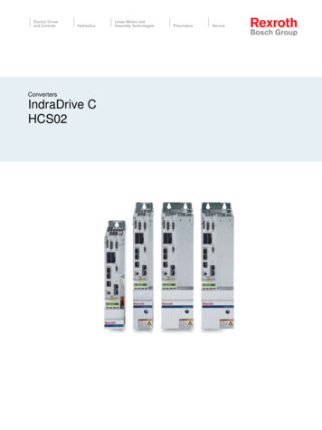
FITTING PROCEDURE1.Remove the original side steps from thevehicle by removing existing four nuts (A) fromside step studs along sill.2.Remove two existing bolts (B) and carefullyremove side rail with help of another person.WARNING – Only remove one side at atime.BA3.Place rubber plugs supplied into the end of theside rails.4.Last Rev Date: 17/05/2007Page 4 of 10Remove all the bolts which go through tothe sill of the vehicle. Like the one shown inthe photograph on the left.Fitting instructions# 3783284Copyright 2005 by ARB Corporation Limited. All rights reserved, this document must not be reproduced without the express authority of ARB Corporation Ltd
5.Using the black M6 dome head bolts plusM6 black flat washer, loosely fit the sillcover. Some of the holes pick up onexisting holes with weld nuts behind them,some pass through existing holes butrequire a flange nut to be fitted on the insideof the sill, and some holes will have to bedrilled.6.For the holes which have to be drilled, usea centre punch to mark the position of thehole in the centre of the slot in the sill cover.7.Remove the sill cover and drill through thesill using a 6.5mm drill. Tough up the baremetal in the hole with black paint.8.Remove the sill cover to prevent damage toit during drilling operations later.NOTE: The sill covers get refitted at the endof the installation process.9.For automatic vehicles, support the weight ofthe gearbox cross member with stand orsimilar. Remove and retain existing bolt forfront bracket.10. For the rear mounting bracket, fit a M12 cagenut into one of the M12 cage nut plates andmake appropriate bend in cage plate to reachthrough the hole shown and position the cagenut behind the hole the M12 bolt will passthrough. As shown in photo on left.11. With the assistance of another person, holdside rail against chassis.12. Using a M12 x 1.75 x 40 bolt(course thread),M12 spring washer and M12 Gold washerloosely fasten into place.NOTE: Leave this bolts finger tight at thisstage.Last Rev Date: 17/05/2007Page 5 of 10Fitting instructions# 3783284Copyright 2005 by ARB Corporation Limited. All rights reserved, this document must not be reproduced without the express authority of ARB Corporation Ltd
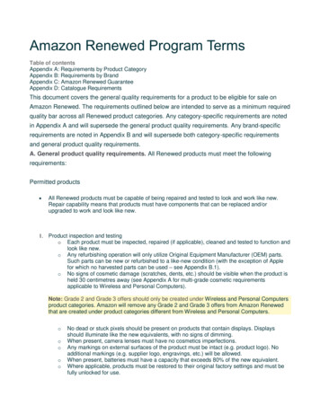
13. Fasten Front Bracket to vehicle as shown.(For Auto vehicles, use the bolt removed instep 8)ANote: For manual vehicles use Bolt M12 X 1.5 X40 (fine pitch), M12 Gold washer and M12 springwasher which are supplied in fitting kit. Use extraM12 Gold washer as packer between chassisand Front Bracket. (Some manual vehicles arefitted with a steel fuel pump cover which securesto the chassis with this bolt. If this is the case, donot use the extra M12 gold washer as a packerbetween the chassis and the rail bracket.)Mark and drill thishole only14.While pushing the side rail to get thevertical face of the front mounting bracketas close to the side of the chassis aspossible, tighten up the bolt “A”.15.Using a marker, mark the position of thehole in the vertical side of the chassis forthe front bracket.16. While using a jack or a leaver, push the centremounting bracket up against the bottom of thechassis. (In the direction of the arrow)17. Using a marker, mark the position of the holein the side of the chassis rail for the centrebracket. (Do not mark or drill the hole in thebottom of the chassis rail at this stage.)Last Rev Date: 17/05/2007Page 6 of 10Fitting instructions# 3783284Copyright 2005 by ARB Corporation Limited. All rights reserved, this document must not be reproduced without the express authority of ARB Corporation Ltd
18.Use a centre punch to mark the centre ofthe marked hole for the front bracket. Thenusing an 11mm drill bit, drill the hole. Becarefull, as depending on the size of yourdrill, the bit will tend to wonder upwardsfrom the market position.Remove any sharp burs, and touch up thebare metal with black paint to preventcorrosion.Warning: Drilling operations can result inflying metal debris, safety glasses should be19.Use a centre punch to mark the centre ofthe marked hole for the centre bracket.Then using an 11mm drill bit, drill the hole.Be carefull, as depending on the size ofyour drill, the bit will tend to wonderupwards from the market position.Remove any sharp burs, and touch up thebare metal with black paint to preventcorrosion.Warning: Drilling operations can result inflying metal debris, safety glasses should beRefit the side rail as follows.Last Rev Date: 17/05/200720.Fit the M12 bolt through the hole into thebottom of the chassis rail.21.Fit an M10 cage nut into M10 cage nutplate and make appropriate bends in cagenut plate to reach the hole in the top of thefront bracket.22.Insert cage nut plate through chassis holeas shown and line up cage nut with holeand bracket.23.Using an M10 x 35 bolt, M10 spring washerand M10 x 25 flat steel washer looselyfasten into place.Page 7 of 10Fitting instructions# 3783284Copyright 2005 by ARB Corporation Limited. All rights reserved, this document must not be reproduced without the express authority of ARB Corporation Ltd
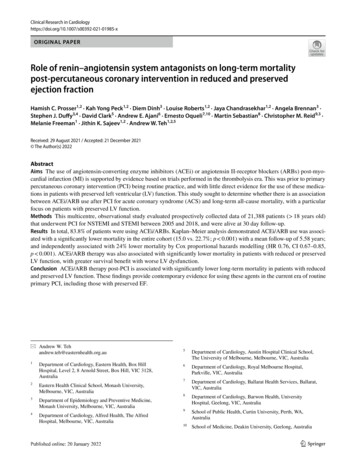
24.For the centre bracket, fit M10 cage nutinto M10 cage nut plate and makeappropriate bends in cage nut plate to reachthe hole.25.Insert cage plate through the hole in thechassis as shown and line up cage nut withhole and bracket.26.Using a M10 x 35 bolt, M10 spring washerand M10 x 25 flat steel washer looselyfasten into place.27.While pushing up on the centre bracket tomake sure that it is up against the bottom ofthe chassis rail, tighten the bolt shown.28. For the rear bracket, fit an M12 cage nut intoone of the M12 cage nut plates and makeappropriate bends in the cage nut plate toreach through the hole shown and position thecage nut behind the hole the M12 bolt willpass through. As shown in photo on left.29. Using a M12 x 40 bolt, M12 spring washer andM12 Gold washer loosely fasten into place.Last Rev Date: 17/05/2007Page 8 of 10Fitting instructions# 3783284Copyright 2005 by ARB Corporation Limited. All rights reserved, this document must not be reproduced without the express authority of ARB Corporation Ltd
30.Using an 11mm drill bit, drill through thebottom of the chassis, using the hole in thebottom of the centre bracket as a guide.Warning: Drilling operations can result inflying metal debris, safety glasses should be31.Clean off any sharp burs, and treat thebare metal surfaces with paint to preventcorrosion.32.Fit an M10 cage nut into M10 cage nutplate and make appropriate bends in cagenut plate to reach the hole in the bottom ofthe chassis member.33.Use an M10 x 35mmbolt, flat and springwasher to fasten the bottom of the centrebracket to the chassis.34.Using an 11mm drill bit, drill through thebottom of the chassis, using the hole in thebottom of the rear bracket as a guide.Warning: Drilling operations can result inflying metal debris, safety glasses should beLast Rev Date: 17/05/200735.Clean off any sharp burs, and treat thebare metal surfaces with paint to preventcorrosion.36.Fit an M10 cage nut into M10 cage nutplate and make appropriate bends in cagenut plate to reach the hole in the bottom ofthe chassis member.37.Use an M10 x 30mm bolt, flat and springwasher to fasten the bottom of the rearbracket to the chassis.38.Finally, refit the sill cover, using the blackM6 dome headed bolts, flat washers andflange nuts as required.Page 9 of 10Fitting instructions# 3783284Copyright 2005 by ARB Corporation Limited. All rights reserved, this document must not be reproduced without the express authority of ARB Corporation Ltd
39.Fit ARB Sticker to rails at the location shown.40. Tighten all bolts to recommended torque.41. Break off all protruding cage nut plates fromchassis.Repeat for the other side of vehicle.Last Rev Date: 17/05/2007Page 10 of 10Fitting instructions# 3783284Copyright 2005 by ARB Corporation Limited. All rights reserved, this document must not be reproduced without the express authority of ARB Corporation Ltd
NOTE: 'WARNING' notes in the fitting procedure relate to OHS situations, where to avoid a potentially hazardous situation it is suggested that protective safety gear be worn or a safe work procedure be employed. If these notes and warnings are not heeded, injury may result. FASTENER TORQUE SETTINGS: SIZE Torque Nm Torque lbft M6 9Nm 4lbft