Transcription
GE PowerGER4930February 2016Liquid Cooled Generator –Stator Winding Connection Ring Test,Repair and UpgradesKarl Tornroos, P.E.Manager, GeneratorServices EngineeringDhruv BhatnagarGenerator Product ServiceAlan IversenGenerator EngineeringSenior EngineerChris RevilleTechnical Leader, GeneratorServices EngineeringEric SchilfSenior Engineer, GeneratorServices EngineeringAndrew Witney, Ph.D. –Materials and ProcessesEngineering Senior Engineer
Liquid Cooled Generator – Stator Winding Connection Ring Test, Repair and UpgradesIntroductionThe average age of a large liquid cooled GE generator is now over35 years and many owners plan to run them for many more years.Large liquid cooled generators were designed for decades of lifewith expected periodic inspection, maintenance and repairs. Forexample, field rewinds and stator rewinds have been routinerefurbishments over the years.One large subcomponent commonly overlooked has been theLiquid Cooled Connection Ring (LCCR) system as most statorrewinds up to now reused the existing connection rings since inmany cases they were in good operating condition.The LCCR system consists of various quantity and sizes of statorwinding connection rings along with the Tetra-loc end windingbasket that support the stator end winding and connection rings.However, older stator winding connection ring system can developreliability issues due to gradual thermal ageing of the ground wallinsulation, gradual deterioration and loosening of the end windingbasket and there is evidence of crevice corrosion in the brazesof the connection rings similar to what we have seen on statorbar clips.2For these reasons GE is now recommending testing and potentialrefurbishment or replacement of connection rings. This documentwill provide more information on this subject including; Recent fleet leak data and recommended inspections andmonitoring Function of Connection Rings and recommended repairs andupgrades More detailed description of the Connection Ring and EndWinding Basket hardware Recent new development of Phos-Free braze upgrades forConnection Rings. Phos-Free refers to a non-phosphoruscontaining braze material.
Liquid Cooled Generator – Stator Winding Connection Ring Test, Repair and UpgradesTable of Contents1. Fleet Experience on Connection Ring Leaks, Monitoring, Inspections and Repairs . . . . 4A.Background. . . . . . . . . . . . . . . . . . . . . . . . . . . . . . . . . . . . . . . . . . . . . . . . . . . . . . . . . . . . . . . . . . . . . . . . . . . . . . . . . . . . . . . . . . . . . . . . . . . . . . . . . . . . . . . . 4B.Leak Data. . . . . . . . . . . . . . . . . . . . . . . . . . . . . . . . . . . . . . . . . . . . . . . . . . . . . . . . . . . . . . . . . . . . . . . . . . . . . . . . . . . . . . . . . . . . . . . . . . . . . . . . . . . . . . . . . . 4C.Testing . . . . . . . . . . . . . . . . . . . . . . . . . . . . . . . . . . . . . . . . . . . . . . . . . . . . . . . . . . . . . . . . . . . . . . . . . . . . . . . . . . . . . . . . . . . . . . . . . . . . . . . . . . . . . . . . . . . . . 4D.Online Monitoring and Repairs. . . . . . . . . . . . . . . . . . . . . . . . . . . . . . . . . . . . . . . . . . . . . . . . . . . . . . . . . . . . . . . . . . . . . . . . . . . . . . . . . . . . . . . . . . . . . . 62. Recommended Repairs and Upgrades. . . . . . . . . . . . . . . . . . . . . . . . . . . . . . . . . . . . . . . . . . . . . . . 7A.Function of and Duty on the LCCR System. . . . . . . . . . . . . . . . . . . . . . . . . . . . . . . . . . . . . . . . . . . . . . . . . . . . . . . . . . . . . . . . . . . . . . . . . . . . . . . . . . . 7B.Failure modes . . . . . . . . . . . . . . . . . . . . . . . . . . . . . . . . . . . . . . . . . . . . . . . . . . . . . . . . . . . . . . . . . . . . . . . . . . . . . . . . . . . . . . . . . . . . . . . . . . . . . . . . . . . . . . 7C.Repair Experience . . . . . . . . . . . . . . . . . . . . . . . . . . . . . . . . . . . . . . . . . . . . . . . . . . . . . . . . . . . . . . . . . . . . . . . . . . . . . . . . . . . . . . . . . . . . . . . . . . . . . . . . . . 8D.Repair Recommendations . . . . . . . . . . . . . . . . . . . . . . . . . . . . . . . . . . . . . . . . . . . . . . . . . . . . . . . . . . . . . . . . . . . . . . . . . . . . . . . . . . . . . . . . . . . . . . . . . . 9E.Replacement of the Connection Rings with the winding in-place. . . . . . . . . . . . . . . . . . . . . . . . . . . . . . . . . . . . . . . . . . . . . . . . . . . . . . . . . . . . . 93. Connection Ring and End Winding Basket Hardware Description. . . . . . . . . . . . . . . . . . . . 10A.Connection Ring Design. . . . . . . . . . . . . . . . . . . . . . . . . . . . . . . . . . . . . . . . . . . . . . . . . . . . . . . . . . . . . . . . . . . . . . . . . . . . . . . . . . . . . . . . . . . . . . . . . . . 10B.End Winding Basket Design. . . . . . . . . . . . . . . . . . . . . . . . . . . . . . . . . . . . . . . . . . . . . . . . . . . . . . . . . . . . . . . . . . . . . . . . . . . . . . . . . . . . . . . . . . . . . . . . 104. Recent new development of Phos-Free Braze Technology in Liquid-Cooled StatorConnection Rings. . . . . . . . . . . . . . . . . . . . . . . . . . . . . . . . . . . . . . . . . . . . . . . . . . . . . . . . . . . . . . . . . . 12A.Root cause of crevice corrosion. . . . . . . . . . . . . . . . . . . . . . . . . . . . . . . . . . . . . . . . . . . . . . . . . . . . . . . . . . . . . . . . . . . . . . . . . . . . . . . . . . . . . . . . . . . . 12B.Development of phos-free brazing technology for stator bars. . . . . . . . . . . . . . . . . . . . . . . . . . . . . . . . . . . . . . . . . . . . . . . . . . . . . . . . . . . . . . 13C.Application of proven technology to connection ring braze joints. . . . . . . . . . . . . . . . . . . . . . . . . . . . . . . . . . . . . . . . . . . . . . . . . . . . . . . . . . . 14D.Enabling technologies development and implementation . . . . . . . . . . . . . . . . . . . . . . . . . . . . . . . . . . . . . . . . . . . . . . . . . . . . . . . . . . . . . . . . . . 14E.Braze joint quality verification strategies. . . . . . . . . . . . . . . . . . . . . . . . . . . . . . . . . . . . . . . . . . . . . . . . . . . . . . . . . . . . . . . . . . . . . . . . . . . . . . . . . . . 15F.First shipment of Phos-Free brazed Connection Rings. . . . . . . . . . . . . . . . . . . . . . . . . . . . . . . . . . . . . . . . . . . . . . . . . . . . . . . . . . . . . . . . . . . . . . 155. Conclusion . . . . . . . . . . . . . . . . . . . . . . . . . . . . . . . . . . . . . . . . . . . . . . . . . . . . . . . . . . . . . . . . . . . . . . . . . 156. Frequently Asked Questions. . . . . . . . . . . . . . . . . . . . . . . . . . . . . . . . . . . . . . . . . . . . . . . . . . . . . . . . 167. Acknowledgements . . . . . . . . . . . . . . . . . . . . . . . . . . . . . . . . . . . . . . . . . . . . . . . . . . . . . . . . . . . . . . . . 178. List of Figures . . . . . . . . . . . . . . . . . . . . . . . . . . . . . . . . . . . . . . . . . . . . . . . . . . . . . . . . . . . . . . . . . . . . . . 179. References. . . . . . . . . . . . . . . . . . . . . . . . . . . . . . . . . . . . . . . . . . . . . . . . . . . . . . . . . . . . . . . . . . . . . . . . . 173
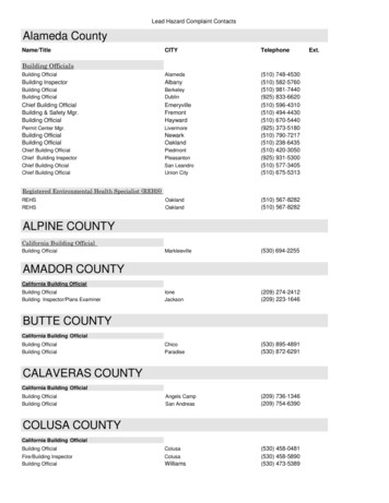
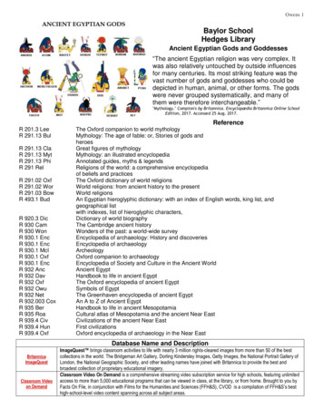
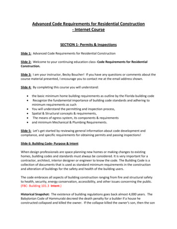
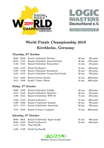
Liquid Cooled Generator – Stator Winding Connection Ring Test, Repair and Upgrades1. Fleet Experience on ConnectionRing Leaks, Monitoring, Inspectionsand RepairsB.A. BackgroundOver the past few years GE has seen systemic leaks in the LiquidCooled Connection Ring (LCCR) System which has affectedreliability and availability. The word ‘System’ refers to theconnection rings and end winding basket described in more detailin Section 3. Recent lab analysis has identified crevice corrosionis occurring similar to what has been experienced in the statorbar clip to strand braze joint. Though the LCCR has not seen thequantity of leaks compared to bar clip to strand leaks and theytypically occur later in the life of the unit. GE believes the cause ofmost of these leaks to be due to crevice corrosion. The mechanismswitches back and forth from crevice corrosion of the braze alloyto acid attack of copper which leads to a development of a leakpath as referenced in GE TIL 1098. The discovery of these leaksis either in service or during an outage or stator rewind anddepending on the size of the leak, the LCCR may require urgentrepair and/or continuous monitoring and/or replacement.The life of a GE generator was expected to be decades withperiodic inspection, maintenance and repairs. Stator bar androtor rewinds have been typical in the industry but the LCCRSystem has typically not been replaced in stator bar rewinds dueto good material condition. But that is changing, the average ageof these liquid cooled connection rings is now over 35 years basedon the number of units in service since commercial operation asshown in Figure 1. So Connection Rings and Tetra-loc end windingbaskets are expected to show more wear as they continue to age.Some customers have now chosen to replace the LCCR Systembased upon leaks, and/or gradual thermal degradation andmechanical wear of the LCCR electrical ground insulationand/or gradual thermal degradation and mechanical wearof the end winding basket.Leak DataTo help customers perform risk assessment GE has compiled dataon the connection ring leaks, as shown in Figure 2. This shows thenumber and location of leaks. This is data we are aware of at thetime of this document and it is reasonable to expect this numberwill continue to grow.Thus, GE now recommends performing actions on connectionrings at outages or during a stator rewind to address potentialleaks and wear. Figure 3 shows leaks identified at an outage orat a stator rewind.C. TestingTesting of the LCCR system should be part of an overall generatortest plan. GE recommends an overall Test and Inspection Planper GEK 103566J but below are some specific highlights fromthe overall testing plan.Offline Leak Testing MethodsOffline leak testing is the best way to determine and quantifythe leak at connection rings. The typical recommendationsfrom GE have been to perform a periodic off-line stator leakmaintenance test program at every minor and major outage.In order to perform offline leak testing, stator preparation isthe key as presence of moisture within the winding can conceala small leak making it undetectable to some leak tests. Themost efficient method of removing water is to perform a “StatorBlowdown” using very dry air. There are situations where the lastremaining moisture trace within the winding must be removedby pulling a vacuum on the system, which will “boil off” thewater. This is a time consuming process and can be minimizedby performing a thorough blowdown prior to vacuum drying.This process is slow in relation to blowdown, but is necessary.Typically, if a winding has been dried well by blowdown, vacuummust be pulled on the winding until it is dry, which can takeapproximately 24 to 36 hours.Number of Units in Service2502001501005000-1010-2020-3030-40Time Since COD (Years)Figure 1 Generator Age440-5050
Liquid Cooled Generator – Stator Winding Connection Ring Test, Repair and UpgradesHydraulic Integrity Test (HIT) Skidhas developed a self-contained, skid-mounted equipment, calleda “HIT Skid” (Hydraulic Integrity Test Skid). Hoses from the skid areconnected to the generator at specified flanges of the stator.To facilitate and expedite the dry out of the water-cooled statorwindings, as well as the Vacuum and Pressure Decay Tests, GEConnection Ring Leaks by Location5Number of 93191919920Majority of leaks are in the lower lead assemblyFigure 2 Connection Ring Leaks by Location5Number of 9971996199519941919931919920Stator RewindFigure 3. Leaks Identified at Outage Inspection or at Rewind5
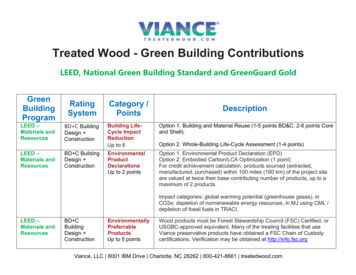
Liquid Cooled Generator – Stator Winding Connection Ring Test, Repair and UpgradesHelium Tracer Gas TestingHelium Tracer Gas Testing is a method of leak detection wherethe generator is pressurized with a helium gas so that possibleleak points can be detected using a helium gas detector. Thereis a wide range of tracer gases and tracer gas detectors on themarket. The Mass Spectrometry technology used by GE employshelium as the tracer gas because it is the lightest inert gas,nontoxic, and non-hazardous. Other gases do not provide thelevel of sensitivity of helium, and some of them can combinewith any residual water in the winding to form acidic solutions.Tracer gas detector sensitivity is very important in finding leaksin the LCCR system. Leak sources can be buried beneath severallayers of glass, mica, and resin within the LCCR system. Thiscan make detection difficult. A process of bagging the localbraze locations (the source of most leaks) has greatly improvedthe ability to locate very small leaks. Helium pressure ismaintained on the system for a period of time to allowhelium from a buried leak to migrate through the insulationand become concentrated in the bag.Leaks that could have been found with the tracer gas will bemissed if LCCR System only had been Vacuum Decay Testedand Pressure Decay Tested based on experience. Early detectionprovides the opportunity to make repairs before more extensivedamage can occur to the ground insulation. To detect small leaks,the sniffer detector must be brought within 2 to 3 inches of theleak. Since it is nearly impossible to cover every square inch ofthe connection rings, tracer test techniques such as baggingthe lower lead area are recommended as it provides bettertest data at higher risk areas of leaks.D. Online Monitoring and RepairsOn-line testing allows for monitoring of the winding conditionover the period between maintenance tests, but is not capableof isolating individual leaks. However, on-line testing is still animportant part of proper stator maintenance. Early detectionand repair are crucial to minimizing the damage that canresult from water within the generator. Periodic monitoringof these indicators should be a fundamental part of operatingall generators with water-cooled stator windings.Stator Leak Monitoring System (SLMS – HP)GE has developed a Stator Leak Monitoring System (SLMS-HP)which is highly recommended for: Oxygenating stator cooling water to therecommended level Monitoring the level of hydrogen escaping out of theYTV ventThe system consists of a flow meter, gas analyzer, data acquisitionand control system and a system piping modification package.The SLMS-HP module is mounted at the hydrogen detraining tankand connects to a gas analyzer and a flow meter which are addedto the existing piping. The system brings fresh filtered air into the6cooling water to provide a measurable gas flow and to maintainthe proper water oxygen content (2 to 8 ppm). Figure below showsthe typical configuration of the SLMS-HP system. Measurementof the hydrogen content and gas flow provides an accuratemeasurement of hydrogen leakage through the stator winding.The level of hydrogen leakage is directly related to leaks in thewater-cooled stator winding and connection rings. Additionally,SLMS-HP aids in minimizing stator bar copper erosion, resin beddamage, rectifier grounds, and stator winding strand blockage.Vent GasPlant ComputerWaterReturn6 CFDSCWSAlarmWater CooledStatorYTVWater Storage TankPower In(110VAC)Plant Air Supply6.5 CFM @ 100 psi6 CFDSLMSSystemDrainPumpCoolingWaterAir InjectionFigure 4ePDALike the main stator winding, the use of partial discharge couplerscan detect long term trending of gradual electrical degradationof the LCCR ground insulation system. So this is a recommendedon-line monitoring system.Summary of Recommended Tests if a Leak onLCCR Develops Continuous on-line monitoring of the connection rings (and restof the stator winding circuit) using SLMS-HP is recommended todetermine development of in-service leaks. Performing periodic HIT skid with Helium Tracer Gas Testing(per GEK103556J) focused on connection rings at the beginningof an outage can help identify a possible leak early in the outagecycle and an extended outage can be minimized. ePDA can be a useful on line trending tool to detectdeterioration of the ground wall insulation. Remember to leverage existing RTD and ThermocoupleMonitoring. Knowing trends in stator bar temperatures can beuseful in overall condition assessment of the connection ringsif a leak is present. For example a high reading thermocoupleand/or RTD (caused by a gas bubble) at a phase bar comparedto normal temperatures can indicate a local leak.
Liquid Cooled Generator – Stator Winding Connection Ring Test, Repair and Upgrades2. Recommended Repairs and UpgradesA. Function of and Duty on the LCCR SystemGE Water-Cooled Connection Rings are a distinct subsystemof the stator winding and are fully contained in the hydrogenboundary within the generator end winding and lower frameextension space. The Connection Rings conduct the stator(armature) current from the stator winding to the high voltagebushings and further downstream to the iso-phase bus/neutralcompartment. The Connection Rings operate at full windingvoltage and experience significant magnetic forces in bothsteady state operation and during transient events (e.g.close in fault, out of phase synchronization).As previously mentioned, the Connection Rings arewater-cooled and are subject to corrosive action in theassembly braze joints. The first GE Water-Cooled ConnectionRing units were shipped in the early 1960’s and GE has usedsimilar design and manufacturing technology on both newWater-Cooled generators and Connection Ring Replacementsuntil 2014. The GE Water-Cooled Connection Ring fleet hasshown to be very reliable overall.Connections Rings are highly stressed components and GErecommends regular test and inspections of the GeneratorSystem including the Connection Rings per GEK 103566J.This includes visual inspection, electrical test (hi-pot) andhydraulic integrity tests. This regimen of testing provides acomplete assessment of the Connection Rings and the resultsof these tests and inspections has typically been the driver formaintenance activities on Connection Rings.B.Failure modesTerminology of Connection RingsThere are two types of rings. A Lead Ring which makes an externalconnection outside of the generator and a Jumper which connectscircuits within the generator. The black lines between the differentcomponents indicates a braze joint locationLead RingLeadAdapterLeadSegmentLeadPlugBraze Joint LocationRing SegmentJumperThe failure of key concern is hydraulic leaks and as documentedin Section 1, Water-Cooled Connection Rings leaks presentsignificant reliability risk.The vast majority of Water-Cooled Connection Ring Leaks havebeen found in the Lead Plug (commonly referred to as the “Tang”or the “Lower Lead ‘) or Lead Adapter (commonly referred to asthe “Pork Chop”) regions of the Connection Ring Assembly. Thetongue and groove braze joint is at particularly high risk for leaks.Reference Figure 5 and Figure 6.BacksetLead Adapter or “Pork Chop”The red components as a whole are called:Terminal Connection lead or “Tang”Lead Plug or “Tang” is the very end piecewith through bolt holesAll Connection Ring Braze Joints contain phosphorus and aresusceptible to Crevice CorrosionFigure 5. Connection Ring TerminologyCollector End Set of Connection RingsConnection RingHeads (Pistols)Typical adverse conditions on Connection Rings that requiremaintenance/repair activity include loose and “greasing” blocking,electrical insulation failures and hydraulic leaks. Repairs toloose and “greasing” blocking typically entails replacement ofthe loose block, re-tying or application of epoxy (e.g. “red-eye).These repairs are considered routine, long term repairs andgenerally do not present future operating risk. Insulation failures,either in-service or during hi-pot testing, are extremely rareto non-existent. GE has no actual documented cases of aWater-Cooled Connection Ring hi-pot failure. Therefore,currently, GE has no actual repair experience for this typeof failure. But this may change in the future.Lower Lead AssemblyConnection Ring SetConnection RingHeads (Pistols)2-Circuit Lead RingFigure 6. Collector End Set of Connection RIngsTypically only about 50% of the linear braze distance in theconnection ring tang (pork chop) is accessible due to the proximityof the adjacent connection rings (even with stripping insulation).The mid arc segments are not accessible due to the proximity ofadjacent rings.Based on typical GE Water-Cooled Connection Ring design,approximately 50% of the brazes are accessible. When you takeinto account the size of a modified TIG torch and length of ahuman arm, and the ability for someone to braze using a mirror,GE estimated that typically 40% of the linear braze distance isrepairable without disassembly of the connection rings.7
Liquid Cooled Generator – Stator Winding Connection Ring Test, Repair and UpgradesC. Repair ExperienceThe recommended repair process for an accessible ConnectionRing Leak is a TIG Braze repair at the leak site.GE has had good experience with successful TIG Braze repairsto accessible Connection Ring leak sites. Reference Figure 7 fora typical accessible leak and Figure 8 of a TIG repair.However, GE has a case (2013) of a connection ring leak locationin the “tang” / “pork chop” tongue and groove joint that wasnon-repairable using the TIG Braze process. The leak rate wasreduced and the unit was returned to service. However, a leak isstill present in the connection ring.Anaerobic Cement has been used in the past for short termrepairs but is not a recommended repair as it is water solubleand requires a vacuum on the water side to draw it into the leak.This can result in a material being drawn into the connection ringand into the water system. Any foreign material in the water sidecan potentially plug a water passage.Figure 7. Typical accessible leak location in Connection Ring “tang” / “porkchop” tongue and groove jointEpoxy Injection (external) is a repair option for connection ringleaks that are inaccessible or non-repairable using TIG brazing.This repair would be considered temporary. The epoxy materialis not water soluble and would be expected to last longer thananaerobic cement.GE has recently experienced two forced outages (a nuclearunit and a fossil unit) since October 2013 due to connectionring leaks. Both units were repaired to an extent that allowed areturn to service.The Connection Ring leak on the nuclear unit was initiallyidentified by a large magnitude step change in the hydrogenleakage rate into the Stator Cooling Water System and detectedby the GE Stator Leak Monitoring System (SLMS HP). This leakalso resulted in a high Stator Cooling Water thermocouple (TC)indication and high Stator Slot resistance temperature detector(RTD) indication. These high temperatures were consistentwith extensive hydrogen gas ingress into the phase statorbar connected electrically and hydraulically to the leakingconnection ring. This occurrence demonstrates the high riskassociated with a Connection Ring leak.TIG BrazeRepairLocationsFigure 8. Successful TIG braze repairGE has experienced a case (2012) of a Connection Ring Leakthat was not accessible for repair. See Figure 9 for a typical view.This type of leak presents a difficult customer risk decision inregards to pursuing a repair solution or operating the unit as isand monitoring the leak. A repair solution for an inaccessible leakwould entail removal of the connection ring from the end windingwith the stator winding in-place. This removal process would behighly intrusive and would require disassembly of the hose, phaseconnections, connection ring support system and flexible leads.In this section, in- situ repairs have been discussed but what aboutreplacement of connection rings with the winding in place?There are technical risks associated with removal and installationof the connection rings with the stator winding in-place. In somecases certain connection rings need to be installed before the8Insulation could not be further removed to expose leak locationdue to overlap concerns, thus rendering leak site inaccessibleFigure 9. Inaccessible Connection Ring Leak
Liquid Cooled Generator – Stator Winding Connection Ring Test, Repair and Upgradesstator bars are installed. So, a connection ring replacement withthe winding in place could require a full lay-out and 3D model todetermine if there would be interferences.GE has not had to perform such a repair yet on the Water-CooledConnection Ring fleet, but has performed 3D modeling on severalhigh risk generators in the fleet to ascertain feasibility of removaland installation of the connection rings with the stator windingin-place. Positive results have been determined from the 3Dmodeling, but each unique generator family will require thissame 3D modeling effort.GE expects to continue to find more connection ring leaksboth in-service from SLMS and during HIT Skid testing due tonormal aging and the susceptibility of the connection ringbraze joints to the crevice corrosion phenomenon.D. Repair RecommendationsConsequently, GE is recommending that Water-CooledConnection Ring users consider long term reliability in theirmaintenance planning.A Liquid Cooled Stator Rewind presents the optimal opportunityto address long term connection ring reliability as the connectionrings are fully accessible for removal and installation with thewinding removed. GE can provide new connection rings utilizinga phosphorus free manufacturing assembly brazing process andcan optimize schedule activities during the stator rewind processto minimize schedule impact. New connection rings with phos-freemanufacturing assembly brazes eliminate concerns with crevicecorrosion and dramatically reduces future leak risk.GE also can remove the existing connection rings and refurbishthem by stripping the existing insulation, re-flowing themanufacturing assembly brazes and re-insulating at the GESchenectady manufacturing plant. Reference Figure 10. Thisrefurbishment process resets the insulation and braze integrityFigure 10. Typical Connection Ring Refurbishmentfor years of expected high reliability. This refurbishment processdoes not eliminate the risk of crevice corrosion as the braze reflowmust be done with the original phosphorous containing braze alloy.Refurbishment can provide outage duration challenges for reducedcycle stator rewind outages. (See Pros and Cons table below.)E.Replacement of the Connection Rings with thewinding in-placeReplacement of the Connection Rings with the winding in-placecan also be considered as a proactive approach or when leakshave been incurred to eliminate reliability concerns withConnection Ring leaks. GE has not performed a replacementof the Connection Rings with the winding in-place on the GEWater-Cooled Connection Ring fleet, but has performed 3Dmodeling on several high risk generators in the fleet to ascertainfeasibility of removal and installation of the connection rings withthe stator winding in-place. Positive results have been determinedfrom the 3D modeling analysis, but each unique generator familywill require this same 3D modeling effort. GE anticipates that thisscope will be performed at some point in the future.Summary of Recommended RepairsProsConsA. TIG braze for spot repair Quick planning and execution Limited to specific leak Still have other potential leak sites Retain older, original end winding basketand other connection rings Braze repair location may be inaccessibleB. Strip insulation, un-braze/re-braze withoriginal type braze material, re-insulateduring rewind outage May be possible to do during anoutage with little up front planningC. New phos-free replacement connectionrings – this is the preferred option. New phos-free brazes - plannedexecution - new end winding basket Uses in kind phos-containing braze Risk of extending outage Retain older, original end winding basket9
Liquid Cooled Generator – Stator Winding Connection Ring Test, Repair and Upgrades3. Connection Ring and End WindingBasket Hardware DescriptionThe majority of the GE Large Steam Turbine Generator fleetwas manufactured in an era when custom designed generatorswere produced to match specific turbine output and gridrequirements. As a result, there are approximately 600 unitsin this fleet, many are similar in design but few have identicalLCCR systems. Each new replacement order involves asubstantial engineering effort which requires a full 3-Dmodel of the end-winding basket and connection rings inorder to upgrade these critical components to currentdesign standards. This comprehensive redesign is one ofthe many steps completed to ensure the new connectionrings fit up correctly to the rest of the generator duringan outage.2 Circuit Lead RingRing SegmentBacksetTerminal or Lead or “Tang”Lead AdapterFigure 11. 2 CIrcuit Lead Ring3 Circuit Lead RingA. Connection Ring DesignThe number of braze joints has been minimized to produceeach connection ring. The necessity of the braze joints may beunderstood with knowledge of the design complexity as well asmanufacturing limitations. For example, a simple connectionring designed for a 2 pole, 2 circuit stator winding contains5 to 8 braze joints, including the lead connector or terminal.This type of ring is shown in Figure 11. The ring segment isconstructed from one large arc section (main ring section)and two backset sections. In addition, the lead connectoror terminal connection adds two or more brazes to thecomplete assembly.Because each backset has multiple precision bends, theyare formed separately and then brazed to the pre-formed ringsegments to ensure the final form of the whole ring assembly.Attempting to manufacture the ring segments and backsets
Thus, GE now recommends performing actions on connection rings at outages or during a stator rewind to address potential leaks and wear. Figure 3 shows leaks identified at an outage or at a stator rewind. C. Testing Testing of the LCCR system should be part of an overall generator test plan. GE recommends an overall Test and Inspection Plan