Transcription
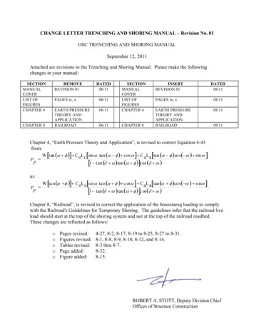
FEMA NATIONAL US&R RESPONSE SYSTEMSTRUCTURAL COLLAPSE TECHNICIAN01-00MODULE 2a SHORING BASICSThe Objectives of this unit are as stated in the adjacent slides. Theoverall purpose of this unit is to explain WHY we build shoring inthe FEMA Response System in the way that we do. In SHORING,PART B the student will be informed as to HOW each type ofshore is constructed. Then all will be given a chance to becomeproficient at building them.TERMINAL OBJECTIVES The Student shall understand the functionand capacity of the various types of Shoringused in US&R to support damaged andcollapsed structures The Student should also understand whythese Shores are constructed in theirspecific configurationsBASIC DEFINITION AND PRINCIPALSShoring is normally the temporary support of structures duringconstruction, demolition, reconstruction, etc. in order to provide thestability that will protect property as well as workers and the public.BASIC DEFINITIONENABLING OBJECTIVESSHORING FOR US&R IS THE TEMPORARY SUPPORT OFONLY THAT PART OF A DAMAGED, COLLAPSED, ORPARTLY COLLAPSED STRUCTURE THAT IS REQUIRED FORCONDUCTING SEARCH AND/OR RESCUE OPERATIONS ATREDUCED RISK TO THE VICTIMS AND US&R FORCESA Shoring system is like double funnel. It needs to collect theload with headers/sheathing, deliver it into the post/struts, and thento distribute it safely into the supporting structure below. A heavilyloaded wood post can punch thru a concrete slab etc.Shoring should be built as a system that has the following:n Header beam, wall plate, other element collects loadn Post or other load carrying element that has adjust ability andpositive end connectionsn Sole plate, bearing plate, or other element to spread the loadinto the ground or other structure below.n Lateral bracing to prevent system from racking (becomingparallelogram), and prevent system from buckling (movingsideways).n Built-in forgiveness (will give warning before failure) Example: Ifvertical shore is proportioned properly, (posts with lengthto width ratio of 25 or less) one can hear the header or solecrush against the post prior to the post starting to fail.Minimum level of lateral strength in any vertical support systemshould be 2% of vertical load, but 10% is desirable whereaftershocks are expected.SM 2A1 Understand the Types and amount ofLoad that needs to be supported byEmergency Shoring Understand what needs to be consideredwhen selecting Shoring to supportDamaged StructuresENABLING OBJECTIVES Understand how Wood Shoring should beconfigured so as to respond with aPredictable and Slow Failure Mode Discuss the Strength and Load Path for thevarious types of Vertical, Sloped and LateralShoring Systems Discuss what types of Shoring Systems aremost commonly used to support Light Frame,Heavy Wall, Heavy Floor and PrecastbuildingsDOUBLE FUNNEL PRINCIPLECOLLECT LOAD NEED POSTS / SHORES withADJUSTABILITY & POSITIVE CONNS NEED LATERAL BRACING NEED SYSTEM with FORGIVENESSDISTRIBUTE LOAD
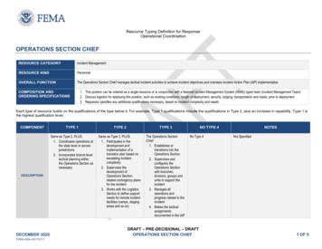
FEMA NATIONAL US&R RESPONSE SYSTEMSTRUCTURAL COLLAPSE TECHNICIAN01-00MODULE 2a SHORING BASICSBASIC DEFINITION AND PRINCIPALS (continued)WEIGHTS OF COMMON BUILDINGMATERIALSTrench Shores provide opposing lateral support - to keeptrench/hole etc. from filling in. Design is normally based on at leasthalf the pressure of water (equivalent fluid weight of at least 45PSFper ft. of depth, PCF) REINFORCED CONCRETE 150 PCFMASONRY 125 PCF WOOD 35 PCF STEEL 490 PCF CONCRETE OR MASONRY RUBBLE 10 PSF PER INCH CONSIDERATIONS FOR DESIGN AND SELECTIONWEIGHTS OF COMMON BUILDING MATERIALS.n Concrete 150 PCFPCF lbs per cubic ftn Masonry 125 PCFPSF lbs per square ftn Wood 35 PCFn Steel 490 PCFn Conc/Masonry Rubble 10PSF PER INCH (of thickness)WEIGHTS OF COMMON BUILDING CONSTRUCTIONn Concrete floors weigh from 90 to 150 PSFn Steel beam w/ concrete-filled metal deck 50-70PSFn Wood floors weigh from 10 to 25 PSF (floors w/ thin concrete fillare 25 PSF or more)n Add 10 to 15 PSF for wood or metal stud interior walls, eachfloor leveln Add 10 PSF or more for furniture/contents each floor (more forstorage, etc.)n Add 10 to 20 PSF for Rescuers 10 PSF on large slab that spreads out load 20PSF on wood floors to allow for concentrationsEXAMPLE: shown in slide at right 20ft x 30ft SlabTotal for 8” concrete slab, 6” of debris, allowance for lights &ceiling, and 10psf for rescuers 105,000 lbs(In this case the 10psf allows for 24-250lb rescuers, whichseems to be reasonable)WEIGHTS OF COMMONBUILDING CONSTRUCTION Concrete floors 90 to 150 psf– Light weight concrete is about 80% Steel systems w/ conc fill slabs 50 to 70 psf Wood floor 10 to 25 psf– (post 1960 wood floors may have concrete fill) Add 10 to 15 psf for wood/metal interior walls– each floor Add 10 psf or more each floor or furniture etc.– More for storage Add 10 psf or more for RescuersEXAMPLE Assume that this 20ft x 30ft classroom has an8” thick concrete roof with 6” of debris on itWHAT IS THE TOTAL LOAD TO SHORE ?8” concrete 100 psf x 20 x 30 60,000 lb6” debris 60 psf x 20 x 30 36,000 lbLights, ducts, ceiling, etc. 5 psf 3,000 lbRescuers 10 psf x 20 x 30 6,000 lb *----------------------------TOTAL* 6,000 lb Rescuers allows for 24 - 250 lb peopleIs this reasonable ? If not use more, this is MINIMUMCAPACITY OF UNDAMAGED, EXISTING CONSTRUCTION.n One undamaged wood or steel framed floor will support onedamaged floorn It normally takes two undamaged concrete floors to support onedamaged floorn The thickness of rubble/debris on damaged floor must also betaken into account.SM 2A2 105,000 lb 105 KipsGENERAL RULES OF THUMBNORMAL CAPACITY OFUNDAMAGED CONSTRUCTION One undamaged wood framed floor willsupport one damaged wood floor One undamaged steel framed floor willsupport one damaged steel floor It takes two undamaged reinforcedconcrete floors to support one damagedconcrete floor
FEMA NATIONAL US&R RESPONSE SYSTEMSTRUCTURAL COLLAPSE TECHNICIAN01-00MODULE 2a SHORING BASICSCONSIDERATIONS FOR DESIGN AND SELECTION continuedNORMAL CAPACITY OFUNDAMAGED CONSTRUCTION SELECTION CONSIDERATIONSUseful info for shoring multi-story buildings.––––Condition of structure to be supportedIs the floor constructed with concrete beams, solid concrete slab,broken slab, etc.? Does the floor have to support masonry rubble?Does the shoring system need to contain an elaborate spreadingsystem, or need one only to support the main beams? Are wesupporting a solid concrete slab/wall or is it a broken masonry wallthat needs more of a spreader system?n In wood floors we can normally place our shoring headerdirectly against the bottom of 2x10 or 2x12 joist, but if the flooror roof is constructed using deep, thin trusses, I-joist, or Trussjoist that may be problematical. Deep, thin members should notbe shored from the bottom without doing something to keepthem from tipping over. shoring should be placed under damagedbeams, etc.multi-level shoring should align from story tostoryThe thickness of debris from heavy, exteriorwalls, etc. must also be taken into account––In URM buildings, wall debris can easily weighmore than a normal storySHORING - SELECTIONCONSIDERATIONS CONDITION OF DAMAGED FLOOR / WALL– SOLID WITH CRACKS– BADLY CRACKED CONCRETE ORMASONRY/URM– WOOD JOIST - WOOD TRUSS– STEEL BEAM - STEEL BAR JOISTn A solution to this problem is to somehow shore from the top ofthis type of member, or to provide some way of keeping themfrom tipping.n In steel floors, beams can be directly shored from the bottom,but steel bar joist present the same problem as wood trusses.The condition of foundation/support of shoring – solid or softground, slab on ground, floor over basement below, rubble, numberof un-damaged stories below, determines extent of system.Availability of shoring materials - pre-plan, local contractors,foreign location.n For collapsed structures want light, portable, adjustable,reliable, and forgiving shoring system.SM 2A3SHORING - SELECTIONCONSIDERATIONS CONDITION OF SUPPORTING SURFACE–– SOLID GROUND - SLAB ON GROUND–– RUBBLE COVERED GROUND OR SLAB–– UNDAMAGED FLOORS IN MULTI-STORYBUILDING–– BASEMENT - BUT NOW MANY FLOORSBELOWAVAILABILITY OF SHORING MATERIALS &LOCAL CONTRACTORS
FEMA NATIONAL US&R RESPONSE SYSTEMSTRUCTURAL COLLAPSE TECHNICIAN01-00MODULE 2a SHORING BASICSCONSIDERATIONS FOR DESIGN AND SELECTION contin.Damaged/Collapsed buildings often contain lateral as well asvertical instability.n Building with cracked (damaged) and out of plumbwalls/columns require lateral support in proportion to the offsetstory, (as much as 10 % of weight of building).SHORING - SELECTIONCONSIDERATIONS Damaged buildings often containvertical as well as lateral instabilities Uncollapsed building have been 10%out of plumb in one story (requireslateral shoring to support 10% of totalweight of building aftershock) The previously discussed Catenarysystems may induce horizontal forces inremainder of buildingn If structure is partly supported by tension structure-like system,horizontal forces are often induced in remaining structure.n Collapses that have large remaining pieces can be extradangerous. Interconnected pieces may depend on each otherfor support. A complicated balancing act to be wary about.n Collapsed structures containing sloped surfaces are especiallydifficult, since loads are vertical due to gravity, but contactsurfaces are sloped, and therefore, vertical and lateral forcesinduced in shoring are both very large.SHORING - SELECTIONCONSIDERATIONS n Total load of structure above can be relatively easily calculated,but where individual load concentrations are being applied isoften difficult to determine. A shoring system that will givewarning of overload is therefore most desirable.n It is difficult to decide on the design load when a damagedstructure is at rest, but of questionable stability. Should vertical shoring support the weight of the damagedbut currently stable floor, or only the weight of rubble restingon it? A four story wood building that is offset one foot in ten in thelower story will require a ten percent stabilizing force, butwhat additional force should be allowed for wind oraftershock?SM 2A4Collapses with large pieces may haveunseen interdependenciesSloped floors & walls are difficult.–– Loads are vertical due to gravity –– Contact surfaces are sloped & lateralforces need to be considered andresisted.TOTAL LOAD OF STRUCTURE EASILY CALCULATED Don’t know where load is concentratedSimilar to mine collapse - unknown archaction Shoring system must give warning ofoverload Brittle failure mode is very undesirable
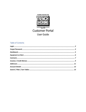
FEMA NATIONAL US&R RESPONSE SYSTEMSTRUCTURAL COLLAPSE TECHNICIAN01-00MODULE 2a SHORING BASICSVERTICAL SHORING SYSTEMSVERTICAL SHORING SYSTEMSWe will now discuss to various types of vertical shoring systemsthat have been successfully used in US&R, as listed on adjacentslide. n These systems are primarily intended to provide verticalsupport, but should all have some lateral bracing for stability.(2% min., 10% reasonable) However, often, individual verticalsupports are initially installed without lateral bracing, in orderreduce risk while constructing a well-braced system.WOOD CAN GIVE WARNING OF OVERLOADn As previously stated, a most desirable property for emergencyshoring is to have a system that will give a warning when it isbecoming overloaded, so that one can mitigate the situation.Wood has a built-in (or more accurately, grown-in) property thatcan be used in our systems to give a noisy indication of highstress. WOOD POSTSELLIS CLAMPST SHORESWINDOW/DOORLACED POSTSCRIBBINGSTEEL PIPETRENCH SHORES METALMETAL FRAMESFRAMES USE UNIQUE PROPERTY OF TIMBER TOPROVIDE WARNING OF OVERLOAD Growth pattern of TreeRapid growth in spring depositsrelatively soft fiberSlower growth rate in summerdeposits more dense fiberIf load end grain, crushing strength isdetermined by summerwoodIf load is on side (crossgrain), softspringwood determines strengthCrossgrain bearing failure is slow &noisy - (gives warning)n As explained in the adjacent slide, most commercial timbergrows in a way that produces softer, spring fibers and harder,summer fibers. By configuring a shoring system such that thelongitudinal grain bears on the cross grain of wood, and thevertical piece is kept short enough that it won’t buckle, we cancause the cross grain to crush.n We can hear and observe this crushing that will occur when thebearing stress is somewhere between 500 and 1000 psi,depending on species of timber.n We want to avoid the condition where the wood post fails inbuckling – a sudden, brittle failure mode. In order to do this weneed to keep the length to width ratio (L/D) of a wood post toless than 25 for the most common lumber used in the U.S.CAPACITY OF WOOD POSTS Slenderness (L/D) determines thebuckling strength of a wood post–– For better failure mode posts should beconstructed so their L/D is less than 25–n Example: 4x4 length for L/D of 25 25x3.5 88" 8ftn As will be discussed next, one can use posts that have L/Dratios up to 50. However, in critical emergency shoringsituations where the load is not known with any degree ofaccuracy and we want to have a system that will give uswarning, it will be more prudent to stay within the L/D 25 limit.SM 2A5Buckling failure is sudden and undesirableThe maximum allowable L/D is 50This will insure that crossgraincrossgrain crushingcan occur and be observed at a load that islower than the Buckling Load.
FEMA NATIONAL US&R RESPONSE SYSTEMSTRUCTURAL COLLAPSE TECHNICIAN01-00MODULE 2a SHORING BASICSCAPACITY OF WOOD POSTSCAPACITY OF WOOD POSTSn Unless kept relatively short, a post’s strength depends onbuckling and varies relative to its length and the modulus ofelasticity (E). Square Posts P/A allow .3E/(L/D) squared Round Posts P/A allow .23E/(L/D) squared. (E varies from 1M to 1.8M PSI depending on wood species. (P/A compression stress) PSI lbs per square inch (L Length, D Least width or Dia., L/D max 50) As stated on pg. 2, if want to hear warning of failure, it isbetter to limit L/D of posts in vertical shores to 25. Example 4x4 max. length 50x3.5 175" 14.5ft 4x4 length for L/D of 25 25x3.5 88" 8ft Slenderness (L/D) determines thebuckling strength of a wood post–– Buckling failure is sudden and undesirableThe maximum allowable L/D is 50For better failure mode posts should beconstructed so their L/D is less than 25–This will insure that crossgraincrossgrain crushingcan occur and be observed at a load that islower than the Buckling Load.CAPACITY OF WOOD POSTSn The strength of a wood post system is determined by: Perpendicular to grain bearing on the header or sole plate(allowable bearing stress varies from 300 PSI to 700PSIdepending on wood species) Vertical capacity of the posts. Strength of header beam and/or sole plate. Strength of ground or structure below sole plate. If posts are kept short (8 ft for 4x4, 12 ft for 6x6) the systemwill give warning of failure by crushing the softer crossgrain(spring wood) at the bearing of the post on the sill or header.n Douglas Fir or Southern Pine are the most common types ofstructural timber used in the U.S. Average values for thesespecies are: E 1,600,000 PSI Compression parallel to grain 1100 PSI Compression perpendicular to grain 600 PSIn The capacity of header beam and sole plate is determined bybending an/or horizontal shear strength. Average values forDouglas Fir and Southern Pine are: Fb extreme fiber bending stress 1500 PSIFh horizontal shear stress 90 PSIn The capacity of a system supported on the ground may belimited by the soil bearing capacity and transverse spreading ofload may be desirable to avoid excess settlement.SM 2A6 For L/D to be 25 or Less–– This is not always possibleIf a post is properly braced at its midheight, it’s Effective length is half it’s Totallength.– 4 x 4 should be kept shorter than 8 feet6 x 6 should be kept shorter than 12 feetBracing must be placed in N-S as well as E-Wdirection and properly nailedFEMA, US&R shoring has lots of bracing
FEMA NATIONAL US&R RESPONSE SYSTEMSTRUCTURAL COLLAPSE TECHNICIAN01-00MODULE 2a SHORING BASICSCAPACITY OF WOOD POSTS (continued)n These systems are normally made adjustable by cutting andshimming with full bearing, opposing, wood wedges.nAll posts should be positively attached at top and bottom. This requirement along with the need for diagonal bracinglimits the ability to readjust the wedges after making theseconnections. If additional adjustment or re-tightening is required (such asafter aftershocks), one may add shims directly under theload or under to sole plate.n All wood post systems should have diagonal wood bracing, innorth-south and east-west direction if possible. Bracing should be designed for at least 2%, of the verticalcapacity of the shoring system. (10% if aftershocks are possible.)VERTICAL WOOD SHORING 3/4” Ply gussets ea. endea. interiorinterior post,post, 11 sidesidemin. (dbl(dbl gusset addon opposite side of diagbrace at post bottom) 2x6 diag braces Full width wedges w/keeper nails. (can’tadjust them) Nail 2x6 diagdiag. bracew/5-16d to sole, headerand to each postLoad Path - Vertical LoadLoadLoadVERTICAL SHORES – NORMAL WOOD POST SYSTEMn The graphic on the following page (SHOR-1) illustrates theconstruction and capacity of the Wood Post, Vertical Shore. Connections at top & bottoms of posts are nailed gussets Diagonal braces are nailed to each post and also providetop & bottom connections for exterior posts. These shores should be built in pairs (8ft o.c. max) with Xbracing placed between them (aftershock conditions)n The connection at the top & bottom of exterior posts is ofspecial interest, since the diagonal must be carefully positionedto transfer the Lateral Load (see Load Path slides). The diagonal must also be nailed to the header, post, sill,and also confine the wedges. A gusset needs to be placed on the opposite side of posts atbottom to reduce risk of sole roll-over and wedge pop-out.ResistanceLoad Path - Lateral LoadResistanceLoadResistanceResistanceVertical Shore - Important Joints 2x6 diagonal needs to be carefullypositioned– to provide a competent load path– to fit 5-16d to header,post & sole– to confine wedges and reduce roll over atbottomheadern The table below the Vertical Shore diagram gives values forposttwo systems based on both post and header beams being In Earthquakes need to add gusset onopposite side of diagonal brace tostressed at there MAXIUM allowable wood values.protect against sole roll-over & wedge The left hand column gives the maximum value for EACHpop-outsolePOST at the listed height (listed in left column) The spacing of posts is the MAXIMUM distance that theheader can span when posts are loaded to their MAXIMUM. If post spacing is reduced, the capacity of system is (If use 4x4 header instead of4x8, span “S” should be half asincreased If the size of the header is reduced, the distance between much).posts must be reduced proportionallySM 2A7
FEMA NATIONAL US&R RESPONSE SYSTEMSTRUCTURAL COLLAPSE TECHNICIAN01-00MODULE 2a SHORING BASICSSM 2A8
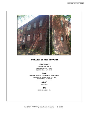
FEMA NATIONAL US&R RESPONSE SYSTEMSTRUCTURAL COLLAPSE TECHNICIAN01-00MODULE 2a SHORING BASICSVERTICAL SHORING SYSTEMS (continued)ELLIS CLAMP - WOOD POST SYSTEMSn 4 x 4 posts can be assembled with Ellis Clamps that give them adjustable length. The failuremode of these assemblies is usually indicated by the crushing of the wood under the clamps,which gives the system some forgiveness. (If shores are 10 ft. or less in height)n These shores use more lumber than single posts, but they can be very useful when working withshort 4x4’s.SM 2A9
FEMA NATIONAL US&R RESPONSE SYSTEMSTRUCTURAL COLLAPSE TECHNICIAN01-00MODULE 2a SHORING BASICSVERTICAL SHORING SYSTEMS (continued)SCREW JACK by ELLISELLIS CLAMP - WOOD POST SYSTEMS (continued)n Metal, adjustable post feet for 4 x 4 & 6 x 6 are made by Ellisand called Screw Jacks. The foot base plate has nail holes forpositive attachment. Adjustable metal foot for 4x4and 6x6 wood posts 6 inch adjustment - set halfway to get 3 in. up & down Metal Foot is stronger thanwood post Use sill beam to spread loadT - SPOT SHOREn This type shore is used for initial stabilization of dangerousareas where fully braced systems (such as Vertical Shores) areto be constructed. They provide temporary support of damaged floors, but theyare basically unstable. They can only support loads that are balanced about thevertical post, and therefore the header needs to be kept to amaximum of 3 feet long.T - SPOT SHORETemporary ShoreBasically UnstableLimit Header to 3 feetand center on LoadStandard, 12” x 12”GussetPost strength isbased on heightas for Vert. ShoreShoren The capacity of the 4x4 post depends on length as in VerticalShores ( 8ft long 4x4 safely supports 8000lb)n They are normally installed with Wedges and a Sole Plate tospread the load and tighten the shore against the load .WINDOW & DOOR SHORESn These Shores have been constructed by Firefighters for years.n They are used mostly in URM buildings to confine and supportloose masonry over openings in the URM walls. They are quite complicated if all corners are properlyconnected and wedges are confined They may also be used in Wood or other buildings wheredoor or window headers have been damaged.n The capacity of the wood posts (which are usually short) usuallydepends on the cross grain bearing strength (between 300 and700psi depending on wood species) A rule of thumb for headers size is to make the depth thesame in inches as the opening width in feet. The header width should be 6 inches for thick, URM walls,but may be 4 inches for thinner walls, such as wood andhollow concrete block (cinder block)n A simpler, pre-constructed configuration is shown in adjacentslide, which uses shims over header and at one side It can be built in safe area and possibly reusedSM 2A10WINDOW / DOOR SHORE( too complicated ? )Ply gussetBe careful oflimited bearingDiagonal cleatat upper wedgesCleats to confinewedges & conn.post to sillUsed for opngsopngs inURM wallsCapacity of shortposts based onBearing StrengthHeader should be1 “ deep for each1’ of opngopng widthX bracing maybe removedfor accessALT - WINDOW / DOOR SHOREPly gussetseach sideeach cornerPre-construct asbox-frame, 1 1/2”min. less than opng.Add wedges on oneside at top & bottom,then shim aboveheader as reqd,Add diagdiag. Bracesif wall is racked, &access isn’t regdregd.
FEMA NATIONAL US&R RESPONSE SYSTEMSTRUCTURAL COLLAPSE TECHNICIAN01-00MODULE 2a SHORING BASICSLACED POSTSn Four posts may be placed in a square pattern and lacedtogether with 2x4 or 2x6 horizontal and diagonal bracing.LACED POSTS Wood Posts spaced 3 to 5 ft Increase long post capacitydue to short effective length Add 2x4 lacing, 3-16d @ endn The strength of each post may then be calculated on the basisof the length/height between lateral braces (horizontals) Need Header & Sole Beamsn Header beams and sole plates usually are required to collectand distribute the load, as with any system. – 3bays3bays bracingbracing ifif overover 12ft12ft highhigh– connectionsconnections areare similarsimilar totoverticalvertical shoreshore (see(see next)next)n The space inside the laced posts may be useful as a safehaven, since it is relatively strong and one may climb inrelatively quicklyn Laced Post Systems are most effectively constructed by firstbuilding two, 2 post vertical shores with appropriate connectionsand then lacing them together.n The connections between diagonals and header/sole need tobe made with as much care as for the Vertical Post Shore,since the 2x4 diagonal must be nailed properly to header, post,sole, and confine the wedges as shown at the right. A gusset is, again, useful opposite the diagonal to soleconnection to guard against roll-over and wedge pop-out.Height NOT exceed 4 x widthCan use as Safe Haven4 - 4x4x16’- 0” 32,000#4 - 6x6x20’- 0” 80,000#Based on 660psi bearingLACED POSTS - CONNECTIONS Need to carefully place diagonalat post to beam & post to sole– nail 3-16d to beam & post at top– nail 3-16d to sole & post at bottom confine wedges Use gusset, one side at otherpost to beam & each side to sole( opposite side diagonal)– 5-8d to post– 8-8d to beam & sole3sCRIBBINGWOOD CRIBBINGn Multi member lay-up of 4x4 to 8x8 lumber in two or threemember per layer configuration. n Capacity is determined by perpendicular to grain load on sum ofall bearing surfaces. n Stability is dependent on height to width of crib and should notexceed 3 to 1. Need to overlap corners a minimum of 4” to guard againstsplitting off corners of individual pieces that can negativelyimpact overall stability.n Cribs used by contractors (or in short-term emergencies) oftenrely only on the friction between bearings for lateral strength,not sufficient for aftershocks.n Individual pieces may be notched like Lincoln logs, to providelateral resistance in addition to the friction between pieces.Metal clips may also be used to improve lateral strength, as wellas diagonal braces between pairs of cribs.SM 2A11 Capacity based on crossgrainbearing area of systemAllow stress varies from 200 to1000psi for wood speciesFor 2 member x 2 member crib4x4 capacity 24,000# (500psi)6x6 capacity 60,000#Limit Height to Width to 3 to 1Overlap corners by 4” to assureslow, crushing failure
FEMA NATIONAL US&R RESPONSE SYSTEMSTRUCTURAL COLLAPSE TECHNICIAN01-00MODULE 2a SHORING BASICSVERTICAL SHORING SYSTEMS (continued)CRIBBING – CAPACITY AND LAYOUTSM 2A12
FEMA NATIONAL US&R RESPONSE SYSTEMSTRUCTURAL COLLAPSE TECHNICIAN01-00MODULE 2a SHORING BASICSSM 2A13
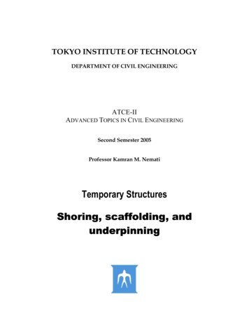
FEMA NATIONAL US&R RESPONSE SYSTEMSTRUCTURAL COLLAPSE TECHNICIAN01-00MODULE 2a SHORING BASICSVERTICAL SHORING SYSTEMS (continued)CRIBBING (continued)WOOD CRIBBINGn Failure is slow, noisy crushing of softer spring wood fibers,which make system very desirable for unknown loading ofUS&R work. In order to assure this desirable failure mode, thecrib corners must be made by overlapping the individual piecesby four inches as previously mentioned. n Solid levels can be placed within the crib to support a jack orspread the load at the ground level.Capacity based on crossgrainbearing area of systemAllow stress varies from 200 to1000psi for wood speciesFor 2 member x 2 member crib4x4 capacity 24,000# (500psi)6x6 capacity 60,000#Limit Height to Width to 3 to 1Overlap corners by 4” to assureslow, crushing failuren Heavily loaded cribbing can crush so that it will loose from 10%to 20% of it’s height. This is a good thing as far as providing warning of overload,but may present problems regarding stability and the needto keep the system tight.n Shrinkage of green lumber will cause crib to shorten and theyshould be checked daily for tightness.n Cribs may be used to support sloped surfaces as will bediscussed laterSTEEL PIPE SYSTEMSn Pipe capacity depends on buckling strength.n P/A allow 0.5E/(L/R) squaredE 29,000,000 PSI(L length; R radius of gyration average radius of pipe)n Retractable pipe shores are normally adjustable by screw endand/or sleeve and pin. They may have square steel feet thatmay even have slope adjustment and nail holes for attachment.n Pipe shores used for bracing tilt-up concrete walls come inlengths up to 30 feet and have rated capacities listed in tablessupplied by rental companies.n Pipe systems are often used with wood spreader beams andsills, which could limit their capacity. Engineers should be usedto design these systems.SM 2A14PIPE SHORES Not in US&R Equipment Cache Rent from Concrete Service Co. Capacity based on Diameter &Length of shore (L/r) 2”dia. pipe x 10-0 6,000#1 1/2” dia. x 7-0 5,000# Capacity of system using woodheader & sole may depend onbase plate area4s
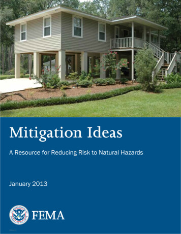
FEMA NATIONAL US&R RESPONSE SYSTEMSTRUCTURAL COLLAPSE TECHNICIAN01-00MODULE 2a SHORING BASICSVERTICAL SHORING SYSTEMS (continued)TRENCH JACKSTRENCH JACKS n Vary from about two to more than eight feet long and normallyhave a rated capacity. They are intended to support theopposing sides of a trench, with the addition of spreaders &sheathingn May be used as initial, unbraced shoring to permit building ofmore stable system.Adjustable screw type can beused either vertical or horizontal Similar capacity to pipe shores System may be limited by endbearing area All pipes should be Schedule 40n If used as only system they will need to be connected tospreaders at top and bottom and should be laterally braced.DIAGONALLY BRACED METAL FRAMESALUMINUM FRAMES & JOISTn Steel and aluminum tubular frames are available in capacitiesup to 50,000lb. per two post frame. They have adjustableheight and spreader systems. They may be stacked and guyedto reach great heights, and have diagonal bracing members. Available in 20k per 2leg frame up to 50k Capacity of framemay depend on footbearing plate AlumaBeams havewood nailer & canspan up to 20’ - Havebeen used as shelter2sALUMA BEAMSALUMA BEAMSn These are light gage, shaped aluminum joist or beams that arenormally used as shoring for wet concrete.7 1/2”191 mmn They have been used to construct shelters from falling debris,as plywood sheathing can be placed between the AlumaBeams and nailed too them to provide a surface that is quiteflexible but strong.Aluma Stringer6 1/2”165 mmBeam5 1/2140 mm140 Beam Available from Concrete Supply (Burke) Up to 20 ft spans - use Plywd Sheathing Good Dynamic Properties to stop fallingobjects more slowly - absorb energy3sn The flexibility of the aluminum (3 times that of a similar steelstructure) is ideal for catching falling objects, since the flexibilityreduces the strength required for the CATCH structure.PNEUMATIC SHORESPNEUMATIC SHORES n Lightweight aluminum pneumatic piston ram shore, which ishighly adjustable with ranges
FEMA NATIONAL US&R RESPONSE SYSTEM STRUCTURAL COLLAPSE TECHNICIAN 01-00 MODULE 2a SHORING BASICS SM 2A 1 The Objectives of this unit are as stated in the adjacent slides. The overall purpose of this unit is to explainWHY we build shoring in the FEMA Response System in the way that we do. In SHORING, PART B the student will be informed as toHOW each type of