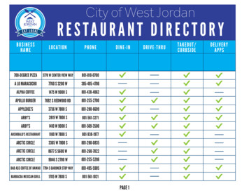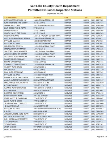
Transcription
HD-801ChapterROADSIDE DESIGNSubjectDesign ElementsGENERAL:AASHTO’s Roadside Design Guide and engineering judgment should beused for roadside safety design.The roadside is the area between the outside edge of the usable shoulderand the right-of-way limits. The area between roadways of a dividedhighway may also be considered the roadside. The roadside is as vital tothe safe operation of a vehicle as the pavement itself.Roadside safety design is a very important component of the totalhighway design and should be thoroughly considered during the designprocess. The goal of roadside safety design is to create a “forgivingroadside,” which allows for errant vehicles leaving the roadway andsupports a roadside design where serious consequences are reduced.In regard to roadside safety considerations, the designer should follow thesuggested options listed below, when feasible:¾¾¾¾¾Remove the obstacle.Redesign the obstacle so that it can be safely traversed.Relocate the obstacle to a point where it is less likely to be struck.Reduce impact severity by using an appropriate breakaway device.Use impact attenuation devices to shield the obstacle and reduceseverity of crashes.¾ Protect the driver through redirection of the errant vehicle.CLEAR ZONE:An important concept in roadside design is the clear zone. Clear zone isthe total roadside area, starting at the edge of the traveled way, availablefor safe use by errant vehicles. The traveled way is the portion of theroadway for movement of vehicles, exclusive of the shoulders.Clear-zone width is not a geometric design element and therefore is notsubject to the Design Exception Process.CONT.01/06Page 1 of 8
ROADSIDE DESIGN—Design ElementsCLEAR ZONE(cont.):HD-801Clear-zone width is dependent upon traffic volumes, design speed, androadside geometry. The designer should consider the context of theexisting and adjacent roadways and associated crash data whenselecting a clear-zone width. The clear zone should be consistent withinthe project corridor. AASHTO’s Roadside Design Guide provides specificinformation.The clear-zone area may consist of a shoulder, a recoverable slope, anonrecoverable slope, and/or a clear runout area. Slopes parallel to theflow of traffic may be identified as recoverable, nonrecoverable, or critical.¾ A recoverable slope is a slope on which a motorist may retain orregain control of the vehicle. Slopes 4:1 and flatter are generallyconsidered recoverable.¾ A nonrecoverable slope is a slope that is considered traversable buton which the errant vehicle will continue to the bottom. Slopesbetween 3:1 and 4:1 may be considered traversable butnonrecoverable.¾ A critical slope is a slope on which the vehicle is likely to overturn.Slopes steeper than 3:1 are generally considered critical.If an area is not likely to be maintained free of fixed objects, it should notbe considered part of the clear-zone area.In addition to side slopes, there are slopes created by median crossovers,berms, driveways, or intersecting side roads. The Roadside DesignGuide refers to these slopes as “transverse slopes.” These are generallymore critical to errant motorists than foreslopes or backslopes becausethey are typically struck head-on by run-off-the-road vehicles. Transverseslopes of 6:1 or flatter are suggested for high-speed roadways.Another important consideration when evaluating clear zone isconfiguration of the roadside ditches in cut situations. The designershould refer to AASHTO’s Roadside Design Guide for specific informationconcerning suggested foreslope and backslope combinations of proposedditches.ROADSIDEBARRIERS:The goal of the road designer is to provide an adequate clear zone. Itshould be noted that barrier protection is a hazard in and of itself. Abarrier should be used when the clear zone is not obtained and when thebarrier is less of a hazard than the object itself. Barriers should complywith the National Cooperative Highway Research Program (NCHRP)Report 350 guidelines.CONT.01/06Page 2 of 8
ROADSIDE DESIGN—Design ElementsROADSIDEBARRIERS(cont.):HD-801A roadside barrier is a longitudinal barrier used to shield motorists fromeither natural or manmade obstacles located along either side of thetraveled way. There are occasions when barriers may be used forreasons other than shielding the motorists from obstacles, for example,road closure barricades and barriers protecting pedestrians and/orsensitive areas.Every highway should be designed, through judicious arrangements andbalance of geometric features, to preclude or minimize the need forbarriers or other protective devices. When it is determined that a barrieris to be utilized, the designer can refer to the Transportation Cabinet’sStandard Drawings and to AASHTO’s Roadside Design Guide for specificinformation concerning lateral offsets, barrier deflection, terrain effects,flare rates, and length of need. KYTC’s Standard Drawings also showsspecific details concerning barriers utilized.When determining the placement of a roadside barrier, the designershould note that the Transportation Cabinet utilizes a fixed vehicleencroachment (divergence) angle of 15 degrees from the edge of thetraveled way to the obstacle. This calculation derives the “Length ofNeed” for the barrier. It should be noted that “Length of Need” beginswith the first nonbreakaway portions of the barrier. The following figure isan illustration of “Length of Need”:CONT.01/06Page 3 of 8
ROADSIDE DESIGN—Design ElementsCURBS:MEDIANBARRIERS:HD-801It should be noted that, except for impacts at very low operating speeds,curbs typically have no redirectional qualities. When a curb is adjacent tothe traveled way, the minimum operational clearance shall be two feet.For roadways with design speed ranging between 30 and 45 mph andwith a curb adjacent to the traveled way, the berm should be free ofobstacles. The use of guardrail within the berm area should be carefullyevaluated. If guardrail is utilized in the berm area, it should present lessof a hazard that the obstacle being shielded.A median barrier is a longitudinal barrier used to separate traffic on adivided highway and prevent an errant vehicle from crossing the highwaymedian. Although similar to roadside barrier designs, most medianbarriers are designed to redirect vehicles striking either side of the barrier.As with all other types of traffic barriers, a median barrier should beinstalled only if the consequences of striking the barrier are expected tobe less severe than if no barrier existed. Median barriers should complywith NCHRP Report 350 guidelines. AASHTO’s Roadside Design Guidehas guidelines for median barrier application. The following figure showssuggested guidelines for median barriers on high-speed roadways:CONT.01/06Page 4 of 8
ROADSIDE DESIGN—Design ElementsHD-801MEDIAN BARRIERS(cont.):When it is determined that a median barrier is to be utilized, the designercan refer to the Transportation Cabinet’s Standard Drawings and toAASHTO’s Roadside Design Guide for placement guidelines. KYTC’sStandard Drawings also provides median barrier selection guidelines.BARRIER ENDTREATMENTS &CRASH CUSHIONS: Barrier end treatments and crash cushions are frequently used tominimize the severity of impacts with fixed objects by graduallydecelerating an impacting vehicle to a stop or redirecting it around theobject of concern. Barrier end treatments and crash cushions shouldcomply with NCHRP Report 350 guidelines.A barrier end treatment or terminal is normally used at the end of aroadside barrier where traffic passes on only one side of the barrier and inone direction only. A crashworthy end treatment is considered essential ifa barrier terminates within the clear zone or is located in an area where itis likely to be struck by an errant motorist. A “crashworthy” feature is onethat has been proven acceptable for use under specified conditions eitherthrough crash-testing or in-service performance.When selecting a leading-end barrier end treatment, the designer shouldconsider the following guideline hierarchy:¾ Barrier anchored in backslope—When properly designed and located,this type of anchor provides full shielding for the identified hazard,eliminates the possibility of an end-on impact with the barrier terminal,and minimizes the likelihood of the vehicle passing behind the rail.¾ Flared terminals—A flared breakaway guardrail end treatment withadequate clear zone behind the gating device is used to providerecovery.¾ Straight-line terminals—A straight-line delineated breakaway endtreatment with adequate clear zone behind the gating device is usedto provide recovery.The grading between the traveled way and the terminal and the approachin front of the terminal should be essentially flat (typically this is theshoulder slope extended). The grading behind any gating end treatmentshould be properly addressed to allow errant vehicle recovery.When considering various end treatments for the trailing end of guardrail,the designer should also consider the potential of vehicles traveling in theopposite direction and impacting the guardrail. KYTC’s StandardDrawings provides details on typical guardrail installations and generalapplications for end treatments.CONT.01/06Page 5 of 8
ROADSIDE DESIGN—Design ElementsHD-801BARRIER ENDTREATMENTS& CRASHCUSHIONS (cont.): Guardrail End Treatment Type 7 shall not be used on the interstatesystem. Guardrail End Treatment Type 7 can be considered on lowspeed/low-volume facilities when an adequate recovery zone isunavailable and/or where conditions preclude the desired performance ofother end treatment types. Appropriate justification should be retained inthe project file anytime Guardrail End Treatment Type 7 is included on aproject.A crash cushion is normally used to shield the end of a fixed object. Itsfunction is to gradually decelerate a vehicle to a safe stop or to redirect avehicle away from the object.When providing a crash cushion to be installed on paved surfaces, CrashCushion Type VI is preferred. This device requires a concrete pad and abolt-down system, as detailed in KYTC’s Standard Drawings.Crash Cushion Type IX or IXA is preferred on earth surfaces. This devicerequires posts and soil tubes, as detailed in Standard Drawings.At-median piers (depressed medians) use a Crash Cushion Type IXattached to a concrete backup with a concrete wall between the piers.AASHTO’s Roadside Design Guide provides specific informationconcerning barrier end treatments and crash cushions. StandardDrawings gives specific details and applications of commonly used barrierend treatments and crash cushions.ALTERNATIVEBARRIERS:Standard guardrail in Kentucky is Strong Post W-Beam. Standard barrierwall in Kentucky is New Jersey-shape concrete barrier. New Jerseyshape concrete barrier may be used as a roadside barrier. Otherapproved systems may be used where appropriate and justified by theproject team. AASHTO’s Roadside Design Guide provides specificinformation for alternative barriers.ROADSIDE DESIGNIN WORK ZONES: The forgiving roadside concept as promoted early in this chapter shouldalso be applied to all work zones as appropriate for the type of work beingdone and to the extent existing roadside conditions allow. Because of thelimited horizontal clearance available and the heightened awareness ofmotorists through work zones, the clear-zone requirements may be moreflexible than those for normal conditions.CONT.01/06Page 6 of 8
ROADSIDE DESIGN—Design ElementsHD-801ROADSIDE DESIGNIN WORK ZONES(cont.):Engineering judgment must be used in applying the clear zone to workzones. Depending on site restrictions, it may be feasible to provide onlyan operational clearance. Thus, determination of the width of a workzone’s clear zone should be on a project-by-project basis, consideringtraffic speeds and volumes, roadway geometrics, available right-of-waywidth, and duration of work.Larger clear-zone space consistent with that used on the overall projectshould be utilized for work zones where roadside space is available. Thelocation of collateral hazards such as idle equipment and material storageshould be controlled and subjected to greater clear-zone widths.AASHTO’s Roadside Design Guide provides specific information fordetermining clear-zone width for work zones.Pavement edge drop-offs may occur during highway work. When notproperly addressed, drop-offs may lead to an errant vehicle’s losingcontrol, with a high potential for a serious accident.No vertical drop-off greater than two inches should occur betweenadjacent lanes where the traffic is expected to cross in a lane-changemaneuver. Warning signs should be placed in advance of the area inaccordance with the Manual on Uniform Traffic Control Devices(MUTCD).When contending with pavement edge drop-offs in construction zones,the designer should consider the following guidance:¾ Less than two inches—no protection requiredWarning signs should be placed in advance of and throughout thedrop-off area.¾ Two to four inches—plastic drums, vertical panels, or barricadesevery 100 feet on tangent sections for speeds of 50 mph or greaterCones may be used in place of plastic drums, vertical panels, orbarricades during daylight hours. For tangent sections with speedsless than 50 mph and for curves, devices should be placed every 50feet. Spacing of devices on tapered sections should be in accordancewith the Manual on Uniform Traffic Control Devices (MUTCD).¾ Greater than four inches—positive separation or wedge with 3:1 orflatter slope neededIf there is five feet or more of distance between the edge of thepavement and the drop-off, then plastic drums, vertical panels, orbarricades may be used. If the drop-off is greater than 12 inches,positive separation is strongly encouraged. If concrete barriers areused, special reflective devices or steady burn lights should be usedfor overnight installations.CONT.01/06Page 7 of 8
HD-801ROADSIDE DESIGN—Design ElementsROADSIDE DESIGNIN WORK ZONES(cont.):For temporary conditions, drop-offs greater than four inches may beprotected with plastic drums, vertical panels, or barricades for shortdistances during daylight hours while work is being done in the drop-offarea.Flare rates for temporary barriers should be selected to provide the mostcost-beneficial safety treatments possible. Benefit/cost analyses oftemporary concrete barriers indicate that total accident costs appear to beminimized for flare rates ranging from 4:1 to 8:1.AASHTO’s Roadside Design Guide and the Transportation Cabinet’sStandard Drawings provide specific information about roadside design inwork zones. 01/06Page 8 of 8
HD-801 01/06 Page 1 of 8 Chapter ROADSIDE DESIGN Subject Design Elements GENERAL: AASHTO's Roadside Design Guide and engineering judgment should be used for roadside safety design. The roadside is the area between the outside edge of the usable shoulder and the right-of-way limits. The area between roadways of a divided