Transcription
FYS3240- 4240Data acquisition & controlIntroductionSpring 2019– Lecture #1Reading: RWI (Real World Instrumentation) Chapter 1.Bekkeng 28.12.2018
TopicsInstrumentation:Data acquisition and control– PC-based and embedded systems
Topics you will learn about Atmel XMEGA Microcontrollers (C-programming)LabVIEW programmingData acquisition (DAQ)Control algorithms and process controlReal-Time and Embedded systemsTime and SynchronizationData fusion and estimation Computer buses and interfaces Networked and distributed systems High-speed data streaming
Curriculum Real World Instrumentation with Python: AutomatedData Acquisition and Control Systems 1st Edition, ISBN13: 978-0596809560– Selected chapters Lecture notes Two “papers”– Stochastic models, estimation and control; by Maybeck– An Introduction to the Kalman Filter; by Welch and Bishop Section 1 and 3 Laboratory exercises
Recommended additional book Hands-On Introduction to LabVIEW forScientists and Engineers 3rd Edition, ISBN13: 978-0190211899– Chapter 1 to 5 for basic LabVIEW
Admin information
Course evaluation Midterm evaluation– Questionnaire After the Exam– Dialog meeting (lecturer, teaching assistants, studentrepresentative group)– Final evaluation Need 1 or 2 students for the student representative group(voluntary)
Exam Usually written exam Written exam only in English! But, you can of course answer inNorwegian!
About the lectures and labs Lectures given in Norwegian (English on request)2 lecture hours per week4 (bachelor) / 5 (master) lab assignments - room V442The lab is “open” every day; note the building opening hours!Submit the lab reports including the source code at devilry.ifi.uio.noThree weeks assigned to each microcontroller lab.Saturday: 08 - 18 if access card without codeSunday : only if you have access card with code
Lab Up to 20 lab groups 2 students for each group– 10 computers available Sign up for a lab group (Monday or Tuesday)!– The lab teaching assistant, Tom Morten Berge, will beavailable from 10.00 to 15.00 on the two lab daysMondayTuesdayWednesday
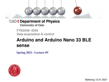
Atmel XMEGA-B1 Xplained evaluation kit
About the lab work Lab 0: LabVIEW introduction with exercises– Learn basic application development with LabVIEW Lab 1: Simple I/O programming– LEDs and switches Lab 2: Control an LCD display Lab 3: Control the ADC (analog to digital converter) Lab 4: Project for Master students (FYS 4240)Microcontrollerlabs– LabVIEW project - Distributed DAQ Sender : Sample video and AI data, and transmit them using UDP (over Ethernet) Receiver: Read UDP data, visualize data and save data to file (TDMS and AVI)
Install LabVIEW on own PC Go to https://www.winprog.uio.no/ Select LabVIEW
Introduction to data acquisition & control
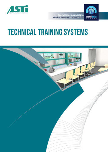
Data acquisition and control - examplesAutonomous carsCERN ALICE DAQDronesCubeSat
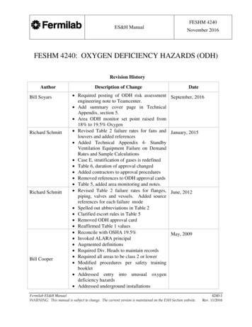
Unmanned Aircraft System (UAS) exampleIMU: Inertial Measurement UnitDAQControl law
Computer-based DAQ systemFYS3240/4240 Configuration Signal processing Display Data Storage PCI DAQ card USB DAQ box PXI DAQ system .
Today – consumer productsEmbedded systemsAerospace & Defence1968ABS Entertainment systemUAV/UAS“The first embeddedcomputer systems”
Data Acquisition (DAQ) & Control Systems The main application domain for Real-Time and Embeddedcomputer systems is within Data Acquisition and Control. A dish washer system reads data from a timer, temperature andwater level sensors, and controls the water valves and heater. Data acquisition involves collecting signals from measurementsources and digitizing the signal for storage, analysis andpresentation.– For a closed-loop control system the acquired and processed dataare also utilized for controlling the process through a feedbackloop.
Open-loop control
Closed-loop control
Automated test setup
Process control
Trends, HW/SW I/O, Data transfer &Parallel processing- Selected background material
Moore’s lawMoore’s law: the number of transistors per square inch on integratedcircuits (or in general, the performance) doubles approximately every 18months.
Trends in Test and Measurement Multicore CPUs and Parallel programming– Increased CPU performance without increased clock rates Software-Defined Instrumentation– Can easily change functionality FPGA-Enabled Instrumentation– High performance, True parallelism, High determinism,High reliability, Reconfigurable 64 bit operating systems– An “unlimited” address space allows much more RAM(Random Access Memory) in the computer Network (Ethernet) connection
Protected mode In computing, protected mode is an operational mode of x86compatible central processing units (CPU)– The term x86 refers to a family of instruction set architectures basedon the Intel 8086 CPU– It allows system software to utilize features such as virtual memory,paging, safe multi-tasking, and other features designed to increasean operating system's control over application software. In protected mode, there are four privilege levels or rings,numbered from 0 to 3, with ring 0 being the most privileged and3 being the least. The use of rings allows for system software torestrict tasks from accessing data or executing privilegedinstructions.In most environments, the operating system and device driversrun in ring 0 and applications run in ring 3– most general-purpose systems (for example Windows 7) use onlytwo rings, even if the hardware they run on provides more CPUmodes.
Privilege levels in WindowsWindows architecture Ring 0 : ”all rights”– operating system (kernel) device drivers Ring 3 : limited rights e.g. related to I/O– Applications (user programs)32 bit Windows XP Need a device driver in order toallow hardware I/O operationsfrom application programs
Device Drivers In computing, a device driver or software driver is a computerprogram allowing higher-level computer programs to interactwith a hardware device. A driver typically communicates with the device through thecomputer bus or communications subsystem to which thehardware connects. When a calling program invokes a routinein the driver, the driver issues commands to the device. Oncethe device sends data back to the driver, the driver may invokeroutines in the original calling program. Drivers are hardwaredependent and operating-system-specific.
Using device drivers in LabVIEW LabVIEW includes custom made drivers for serial communication,TCP, UDP, USB, DAQ etc. All National instruments (NI) hardware is shipped with LabVIEW drivers Device drivers for specific instruments etc. can be downloaded fromNI.com After your hardware driver software is installed, it is integrated intoLabVIEW Most DAQ cards from other manufacturers also have LabVIEW drivers Therefore, usually no device driver has to be written!
Interrupts One method to move acquired data to system memory (from aDAQ-card) is to generate an interrupt request (IRQ). signal.This signal can be generated when one sample is acquired orwhen multiple samples are acquired. The process oftransferring data to system memory via interrupts is givenbelow:– When data is ready for transfer, the CPU stops whatever it is doingand runs a special interrupt handler routine that saves the currentmachine registers, and then sets them to access the board.– The data is extracted from the board and placed into systemmemory.– The saved machine registers are restored, and the CPU returns tothe original interrupted process. The actual data move is fairly quick, but there is a lot ofoverhead time spent saving, setting up, and restoring theregister information.
DMA introduction Direct memory access (DMA) is a system wherebysamples are automatically stored in system memorywhile the processor (CPU) does something else. A computer usually supports several DMA channels.
DMA (direct memory access) I DMA permits peripherals, such as a DAQ-card, to transfer datadirectly to or from memory without having each byte handled bythe processor (CPU). Thus DMA enables more efficient use ofinterrupts, and increases data throughput. The process of transferring data via DMA is given below:– When data is ready for transfer, the DAQ-card notifies theDMA controller.– The DMA controller then asserts a DMA request signal tothe CPU, asking its permission to use the bus (data bus,address bus, control bus).– The CPU completes its current bus activity, stops driving thebus, and returns a DMA acknowledge signal to the DMAcontroller.– The DMA controller then reads and writes one or morememory bytes, driving the address, data, and control signalsas if it were itself the CPU.
DMA (direct memory access) II– When the transfer is complete, the DMA controller stopsdriving the bus and deasserts the DMA request signal. TheCPU can then remove its DMA acknowledge signal andresume control of the bus.– In single-cycle mode, the DMA controller gives up the busafter each transfer. This minimizes the amount of time thatthe DMA controller keeps the processor off of the memorybus, but it requires that the bus request/acknowledgesequence be performed for every transfer. This overheadcan result in a drop in overall system throughput if a lot ofdata needs to be transferred.– In burst mode, the DMA controller keeps control of the busuntil all the data buffered by the requesting device has beentransferred to memory (or when the output device buffer isfull, if writing to a peripheral).
Need for parallel programming Before 2005 innovations in processor technology resulted incomputers with CPUs that operate at higher clock rates. However, as clock rates approached their theoretical physicallimits, companies developed new processors with multipleprocessing cores.– P ACV2f (P is consumed power, A is active chip area, C is the switchedcapacitance, f is frequency and V is voltage). With multicore processors the best performance and highestthroughput is achieved by using parallel programmingtechniques
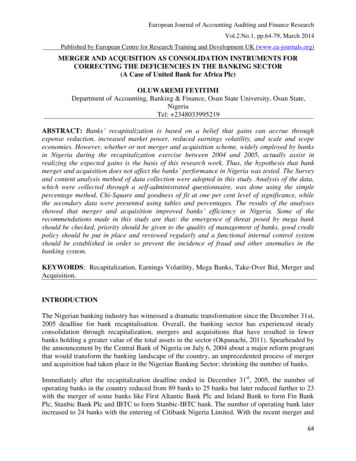
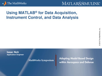
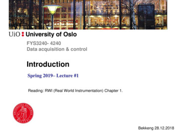
Multiprocessors & MulticoreProcessorsMultiprocessor systems contain multipleCPUs that are not on the same chipThe multiprocessor system has adivided cache with long-interconnectsMulticore Processors contain anynumber of multiple CPUs on asingle chipThe multicore processors share thecache with short interconnectsLowest inter-processorcommunication latency Fastest program execution time
Multicore Programming Goals Increase code execution speed– execution time: time from start to completion of task (response time) Maintain rate of execution but increase data throughput– throughput is the amount of work that can be done in a given time Evenly balance tasks across available CPUs (fair distribution ofprocessing load) Dedicate time-critical tasks to a single CPUIn computing, FLOPS (floating-point operations persecond) is a measure of a computer's performancehttp://www.top500.org/
Multicore Programming Challenges Thread (loop) Synchronization– Data loss (too slow data read vs. data write)– Reading the same data point multiple times Race Conditions– Uncertain result due to shared resources Deadlocks– Two or more processes are each waiting for the other to finish
Hyper-threading Hyper-threading is a technology that was introduced by Intel, with theprimary purpose of improving support for multi-threaded code. Under certain workloads hyper-threading technology provides amore efficient use of CPU resources by executing threads inparallel on a single processor. Hyper-threading works by duplicating certain sections of theprocessor. A hyper-threading equipped processor (core) pretends to be two"logical" processors to the host operating system, allowing theoperating system to schedule two threads or processessimultaneously. E.g. Xeon, Core i5 and Core i7 Intel processors implement hyperthreading.
Hardware acceleration Normally, processors (CPUs) are sequential, and instructions are executed oneby one. In computing, hardware acceleration is the use of computer hardware toperform some function faster than is possible in software running on thegeneral-purpose CPU. The main difference between hardware and software is concurrency, allowinghardware to be much faster than software. Hardware accelerators are designedfor computationally intensive software code Examples of hardware accelerators includes graphics processing units (GPUs)and field-programmable gate array (FPGA)
DMA permits peripherals, such as a DAQ-card, to transfer data directly to or from memory without having each byte handled by the processor (CPU). Thus DMA enables more efficient use of interrupts, and increases data throughput. The process of transferring data via DMA is given below: -When data is ready for transfer, the DAQ-card notifies the