Transcription
IBM System x3550 Type 7978User’s Guide
IBM System x3550 Type 7978User’s Guide
Note:Before using this information and the product it supports, read the general information in “Notices,” on page 77.Second Edition (August 2006) Copyright International Business Machines Corporation 2006. All rights reserved.US Government Users Restricted Rights – Use, duplication or disclosure restricted by GSA ADP Schedule Contractwith IBM Corp.
ContentsSafety. . . . . . . . . . . . . . . . . . . . . . . . . . . . vChapter 1. The System x3550 Type 7978 server .Related documentation . . . . . . . . . . .Notices and statements used in this document . . .Features and specifications . . . . . . . . . .What your server offers . . . . . . . . . . .Reliability, availability, and serviceability . . . . .IBM Director . . . . . . . . . . . . . . .The UpdateXpress program . . . . . . . . .Server controls, LEDs, and power . . . . . . .Front view . . . . . . . . . . . . . .Light path diagnostics panel . . . . . . . .Rear view . . . . . . . . . . . . . . .Server power features . . . . . . . . . . 1. 2. 3. 4. 6. 8. 9. 9. 10. 10. 12. 13. 14Chapter 2. Installing options . . . . . . . .Server components . . . . . . . . . . . .System-board internal connectors . . . . . .System-board external connectors . . . . . .System-board switches and jumpers . . . . .System-board LEDs . . . . . . . . . . .System-board channels and baffles . . . . .System-board option connectors . . . . . .Installation guidelines . . . . . . . . . . .System reliability guidelines . . . . . . . .Working inside the server with the power on . .Handling static-sensitive devices . . . . . .Removing the server cover . . . . . . . . .Removing air baffles . . . . . . . . . . . .Installing a hot-swap power supply . . . . . .Installing a Y power cable . . . . . . . . . .Installing a hard disk drive . . . . . . . . . .Installing a hot-swap hard disk drive . . . . .Installing a simple-swap hard disk drive . . . .Replacing a riser-card assembly . . . . . . .Installing an adapter . . . . . . . . . . . .Replacing the RAID SAS controller . . . . . .Installing a memory module . . . . . . . . .Installing a microprocessor . . . . . . . . .Installing a fan . . . . . . . . . . . . . .Installing a Remote Supervisor Adapter II SlimLine .Completing the installation. . . . . . . . . .Replacing the server cover . . . . . . . .Connecting the cables . . . . . . . . . .Updating the server configuration . . . . . 34445454647Chapter 3. Configuring the server . . . . . .Using the Configuration/Setup Utility program . .Starting the Configuration/Setup Utility program .Configuration/Setup Utility menu choices . . .Passwords . . . . . . . . . . . . . .Using the Boot Menu program . . . . . . . .494950505455 Copyright IBM Corp. 2006.iii
Starting the backup BIOS . . . . . . . . . . . . . . . . . . . .Using the ServerGuide Setup and Installation CD . . . . . . . . . . .ServerGuide features . . . . . . . . . . . . . . . . . . . .Setup and configuration overview . . . . . . . . . . . . . . . .Typical operating-system installation . . . . . . . . . . . . . . .Installing your operating system without ServerGuide . . . . . . . . .Using the baseboard management controller . . . . . . . . . . . . .Enabling and configuring SOL using the OSA SMBridge management utilityprogram . . . . . . . . . . . . . . . . . . . . . . . .Installing the OSA SMBridge management utility program . . . . . . .Using the baseboard management controller utility programs . . . . . .Configuring the Gigabit Ethernet controller . . . . . . . . . . . . . .Configuring hot-swap SAS or hot-swap SATA RAID . . . . . . . . . .Using the IBM ServeRAID Configuration Utility program . . . . . . . .Using ServeRAID Manager . . . . . . . . . . . . . . . . . .Configuring simple-swap SATA RAID . . . . . . . . . . . . . . . .Using the Adaptec RAID Configuration Utility program . . . . . . . .Setting up an Remote Supervisor Adapter II SlimLine . . . . . . . . . .Requirements . . . . . . . . . . . . . . . . . . . . . . .Cabling the Remote Supervisor Adapter II SlimLine . . . . . . . . .Installing the Remote Supervisor Adapter II SlimLine firmware . . . . .Completing the setup . . . . . . . . . . . . . . . . . . . ix. Notices . . . . . . . . . . . . . . . .Trademarks . . . . . . . . . . . . . . . . . . .Important notes . . . . . . . . . . . . . . . . . .Product recycling and disposal . . . . . . . . . . . .Battery return program . . . . . . . . . . . . . . .Electronic emission notices . . . . . . . . . . . . .Federal Communications Commission (FCC) statement . .Industry Canada Class A emission compliance statement .Australia and New Zealand Class A statement . . . . .United Kingdom telecommunications safety requirement . .European Union EMC Directive conformance statement . .Taiwanese Class A warning statement . . . . . . . .Chinese Class A warning statement . . . . . . . . .Japanese Voluntary Control Council for Interference (VCCI).7777787980818181818182828282. . . . . . . . . . . . . . . . . . . . . . . . . . . . . . . . . . . . . . . .statement.Index . . . . . . . . . . . . . . . . . . . . . . . . . . . . 83ivIBM System x3550 Type 7978: User’s Guide
SafetyBefore installing this product, read the Safety Information.Antes de instalar este produto, leia as Informações de Segurança.Pred instalací tohoto produktu si prectete prírucku bezpecnostních instrukcí.Læs sikkerhedsforskrifterne, før du installerer dette produkt.Lees voordat u dit product installeert eerst de veiligheidsvoorschriften.Ennen kuin asennat tämän tuotteen, lue turvaohjeet kohdasta Safety Information.Avant d’installer ce produit, lisez les consignes de sécurité.Vor der Installation dieses Produkts die Sicherheitshinweise lesen.Prima di installare questo prodotto, leggere le Informazioni sulla Sicurezza.Les sikkerhetsinformasjonen (Safety Information) før du installerer dette produktet.Antes de instalar este produto, leia as Informações sobre Segurança. Copyright IBM Corp. 2006v
Antes de instalar este producto, lea la información de seguridad.Läs säkerhetsinformationen innan du installerar den här produkten.Important:All caution and danger statements in this documentation begin with anumber. This number is used to cross reference an English caution ordanger statement with translated versions of the caution or dangerstatement in the IBM Safety Information book.For example, if a caution statement begins with a number 1,translations for that caution statement appear in the IBM SafetyInformation book under statement 1.Be sure to read all caution and danger statements in thisdocumentation before performing the instructions. Read any additionalsafety information that comes with the server or optional device beforeyou install the device.viIBM System x3550 Type 7978: User’s Guide
Statement 1:DANGERElectrical current from power, telephone, and communication cables ishazardous.To avoid a shock hazard:v Do not connect or disconnect any cables or perform installation,maintenance, or reconfiguration of this product during an electricalstorm.v Connect all power cords to a properly wired and grounded electricaloutlet.v Connect to properly wired outlets any equipment that will be attached tothis product.v When possible, use one hand only to connect or disconnect signalcables.v Never turn on any equipment when there is evidence of fire, water, orstructural damage.v Disconnect the attached power cords, telecommunications systems,networks, and modems before you open the device covers, unlessinstructed otherwise in the installation and configuration procedures.v Connect and disconnect cables as described in the following table wheninstalling, moving, or opening covers on this product or attacheddevices.To Connect:To Disconnect:1. Turn everything OFF.1. Turn everything OFF.2. First, attach all cables to devices.2. First, remove power cords from outlet.3. Attach signal cables to connectors.3. Remove signal cables from connectors.4. Attach power cords to outlet.4. Remove all cables from devices.5. Turn device ON.Safetyvii
Statement 2:CAUTION:When replacing the lithium battery, use only IBM Part Number 33F8354 or anequivalent type battery recommended by the manufacturer. If your system hasa module containing a lithium battery, replace it only with the same moduletype made by the same manufacturer. The battery contains lithium and canexplode if not properly used, handled, or disposed of.Do not:v Throw or immerse into waterv Heat to more than 100 C (212 F)v Repair or disassembleDispose of the battery as required by local ordinances or regulations.viiiIBM System x3550 Type 7978: User’s Guide
Statement 3:CAUTION:When laser products (such as CD-ROMs, DVD drives, fiber optic devices, ortransmitters) are installed, note the following:v Do not remove the covers. Removing the covers of the laser product couldresult in exposure to hazardous laser radiation. There are no serviceableparts inside the device.v Use of controls or adjustments or performance of procedures other thanthose specified herein might result in hazardous radiation exposure.DANGERSome laser products contain an embedded Class 3A or Class 3B laserdiode. Note the following.Laser radiation when open. Do not stare into the beam, do not view directlywith optical instruments, and avoid direct exposure to the beam.Class 1 Laser ProductLaser Klasse 1Laser Klass 1Luokan 1 LaserlaiteAppareil A Laser de Classe 1Safetyix
Statement 4: 18 kg (39.7 lb.) 32 kg (70.5 lb.) 55 kg (121.2 lb.)CAUTION:Use safe practices when lifting.Statement 5:CAUTION:The power control button on the device and the power switch on the powersupply do not turn off the electrical current supplied to the device. The devicealso might have more than one power cord. To remove all electrical currentfrom the device, ensure that all power cords are disconnected from the powersource.21xIBM System x3550 Type 7978: User’s Guide
Statement 6:CAUTION:Do not place any objects on top of a rack-mounted device unless thatrack-mounted device is intended for use as a shelf.Statement 8:CAUTION:Never remove the cover on a power supply or any part that has the followinglabel attached.Hazardous voltage, current, and energy levels are present inside anycomponent that has this label attached. There are no serviceable parts insidethese components. If you suspect a problem with one of these parts, contacta service technician.Statement 12:CAUTION:The following label indicates a hot surface nearby.Safetyxi
Statement 26:CAUTION:Do not place any object on top of rack-mounted devices.xiiIBM System x3550 Type 7978: User’s Guide
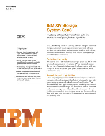
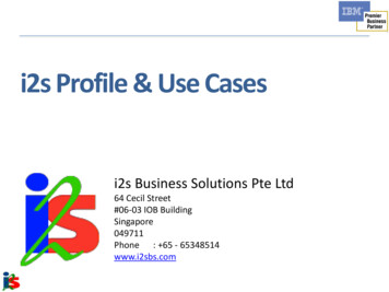
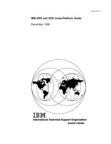
Chapter 1. The System x3550 Type 7978 serverThe IBM System x3550 Type 7978 server is a 1-U-high1 rack model server forhigh-volume network transaction processing. This high-performance, dual coreserver is ideally suited for networking environments that require superiormicroprocessor performance, input/output (I/O) flexibility, and high manageability.The System x3550 server supports one of the following hard disk driveconfigurations:v Servers with four hot-swap bays support 2.5-inch hot-swap Serial Attached SCSI(SAS) hard disk drives. You can install only 2.5-inch hot-swap SAS drives inthese servers.The following illustration shows a System x3550 server with a 2.5-inch hard diskdrive configuration.USB 3 connectorUSB 4 connectorVideo connectorRack release latch2.5-inch hard disk drivesHard disk drivestatus LEDHard disk driveactivity LEDOperator informationpanelRack release latchCD-RW/DVD eject buttonCD-RW/DVD drive activity LEDv Servers with two hot-swap bays support 3.5-inch hot-swap SAS or 3.5-inchhot-swap Serial ATA (SATA) hard disk drives. You can install only 3.5-inchhot-swap SAS or hot-swap SATA drives in these servers.v Servers with two simple-swap bays support 3.5-inch simple-swap SATA hard diskdrives. You can install only 3.5-inch simple-swap SATA drives in these servers.The following illustration shows a System x3550 server with a hot-swap orsimple-swap 3.5-inch hard disk drive configuration.Hard diskdrive activityHard diskdrive statusRack release latchUSB 3 connectorUSB 4 connectorVideo connector3.5 inch hard disk drivesOperator information panelRack release latchCD-RW/DVD eject buttonCD-RW/DVD drive activity LEDCD-RW/DVD drivePerformance, ease of use, reliability, and expansion capabilities were keyconsiderations in the design of the server. These design features make it possiblefor you to customize the system hardware to meet your needs today and provideflexible expansion capabilities for the future.1. Racks are marked in vertical increments of 1.75 inches each. Each increment is referred to as a unit, or a “U”. A 1-U-high deviceis approximately 1.75 inches tall. Copyright IBM Corp. 20061
The server comes with a limited warranty. For information about the terms of thewarranty and getting service and assistance, see the Warranty and SupportInformation document.The server contains IBM Enterprise X-Architecture technologies, which helpincrease performance and reliability. For more information, see “What your serveroffers” on page 6 and “Reliability, availability, and serviceability” on page 8.You can obtain up-to-date information about the server and other IBM serverproducts at http://www.ibm.com/systems/x/.Related documentationThis User’s Guide provides general information about the server, including how toinstall supported options and how to configure the server. The followingdocumentation also comes with the server:v Installation GuideThis printed document contains instructions for setting up the server and basicinstructions for installing some options.v Safety InformationThis document is in Portable Document Format (PDF) on the IBM System xDocumentation CD. It contains translated caution and danger statements. Eachcaution and danger statement that appears in the documentation has a numberthat you can use to locate the corresponding statement in your language in theSafety Information document.v Rack Installation InstructionsThis printed document contains instructions for installing the server in a rack.v Problem Determination and Service GuideThis document is in PDF on the IBM System x Documentation CD. It containsinformation to help you solve problems yourself, and it contains information forservice technicians.v Warranty and Support InformationThis document is in PDF on the IBM System x Documentation CD. It containsinformation about the terms of the warranty and getting service and assistance.Depending on the server model, additional documentation might be included on theIBM System x Documentation CD.The xSeries Tools Center is an online information center that contains informationabout tools for updating, managing, and deploying firmware, device drivers, andoperating systems. The xSeries Tools Center is at v1r0/index.jsp.The server might have features that are not described in the documentation thatyou received with the server. The documentation might be updated occasionally toinclude information about those features, or technical updates might be available toprovide additional information that is not included in the server documentation.These updates are available from the IBM Web site. To check for updates, go es/index.html, select Systemx3550 from the Hardware list, and click Go. For firmware updates, click theDownload tab. For Documentation updates, click the Install and use tab, and clickProduct documentation.2IBM System x3550 Type 7978: User’s Guide
Notices and statements used in this documentThe caution and danger statements that appear in this document are also in themultilingual Safety Information document, which is on the IBM System xDocumentation CD. Each statement is numbered for reference to the correspondingstatement in the Safety Information document.The following notices and statements are used in this document:v Note: These notices provide important tips, guidance, or advice.v Important: These notices provide information or advice that might help you avoidinconvenient or problem situations.v Attention: These notices indicate potential damage to programs, devices, ordata. An attention notice is placed just before the instruction or situation in whichdamage could occur.v Caution: These statements indicate situations that can be potentially hazardousto you. A caution statement is placed just before the description of a potentiallyhazardous procedure step or situation.v Danger: These statements indicate situations that can be potentially lethal orextremely hazardous to you. A danger statement is placed just before thedescription of a potentially lethal or extremely hazardous procedure step orsituation.Chapter 1. The System x3550 Type 7978 server3
Features and specificationsThe following information is a summary of the features and specifications of theserver. Depending on the form factor server, some features might not be available,or some specifications might not apply.4IBM System x3550 Type 7978: User’s Guide
Table 1. Features and specificationsMicroprocessor: Power supply:Heat output:Maximum of two redundant 670-watt(110 or 220 V ac auto-sensing)hot-swap power supplies.Approximate heat output in Britishthermal units (Btu) per hour:v Minimum configuration: 662 Btu perhour (194 watts)v Maximum configuration: 2390 Btuper hour (700 watts) v Intel Xeon FC-LGA 771dual-core with 4096 KB (minimum)Level-2 cachev Support for up to twomicroprocessorsv Support for Intel Extended Memory64 Technology (EM64T)Note:v Use the Configuration/Setup Utilityprogram to determine the type andspeed of the microprocessors.Hot-swap fans:v Standard: fivev Maximum: six (with twomicroprocessors installed)Size:v Height: 43 mm (1.69 inches, 1 U)v Depth: 711 mm (28 inches)v Width: 440 mm (17.3 inches)v Maximum weight: 15.4 kg (34 lb)when fully configuredv For a list of supportedmicroprocessors, /compat/us/Integrated functions:v Two Broadcom NetXtreme II GbMemory:Ethernet controllers with TOE andv Minimum: 1 GBWake on LAN supportv Maximum: 32 GBv Four Universal Serial Bus (USB)v Type: PC2-5300, 667 MHz, ECC,2.0 ports (two front and two rear)DDR II fully buffered SDRAMv One Advanced SystemDIMMs onlyManagement RJ-45 (active onlyv Slots: Eight dual inlinewhen a Remote Supervisorv Supports 512 MB, 1 GB, 2 GB, andAdapter II SlimLine is installed)4 GB (when available) DIMMsv One serial portDrives:CD/DVD: IDE 24x CD-RW/ 8x DVDcombinationExpansion bays (depending onmodel):Either two 3.5-inch or four 2.5-inchhard disk drive baysv Servers with a 2.5-inch hot-swapdrive bay configuration support upto four 2.5-inch hot-swap SAS harddisk drivesv Servers with a 3.5-inch hot-swapdrive bay configuration support upto two 3.5-inch SAS or SATAhot-swap hard disk drivesv Servers with a 3.5-inchsimple-swap drive bay configurationsupport up to two 3.5-inchsimple-swap SATA hard disk drivesHard disk controllers:v Serial ATA (SATA) controller withintegrated RAID (simple-swapSATA models)v Serial-attached SCSI (SAS)controller with integrated RAID(hot-swap SAS models)Acoustical noise emissions:v Sound power, idling: 6.8 belsmaximumv Sound power, operating: 6.8 belsmaximumEnvironment:v Air temperature:– Server on: 10 to 35 C (50.0 to 95.0 F); altitude: 0 to 914 m(2998.7 ft)– Server off: -40 to 60 C(-104 to 140 F); maximumaltitude: 2133 m (6998.0 ft)vHumidity:PCI Expansion slots:– Server on: 8% to 80%v One PCI Express x8 (half length)– Server off: 8% to 80%v One PCI Express x8 (half length) orPCI-X (half length)Electrical input:v Sine-wave input (47-63 Hz) requiredv Input voltage low range:– Minimum: 100 V ac– Maximum: 127 V acv Input voltage high range:– Minimum: 200 V ac– Maximum: 240 V acv Input kilovolt-amperes (kVA),approximately:– Minimum: 0.194 kVA– Maximum: 0.700 kVAVideo controller (integrated):v ATI Radeon RN50 (dual ports - frontand rear)v Support for SPI Serial flash memoryvideo BIOSv Flexible memory support– 8 MB to 256 MB– DDR1 and DDR2 SDRAM andSGRAMNotes:1. Power consumption and heatoutput vary depending on thenumber and type of optionalfeatures installed and thepower-management optionalfeatures in use.2. These levels were measured incontrolled acoustical environmentsaccording to the proceduresspecified by the American NationalStandards Institute (ANSI) S12.10and ISO 7779 and are reported inaccordance with ISO 9296. Actualsound-pressure levels in a givenlocation might exceed the averagevalues stated because of roomreflections and other nearby noisesources. The declared sound-powerlevels indicate an upper limit, belowwhich a large number of computerswill operate.Chapter 1. The System x3550 Type 7978 server5
What your server offersThe server uses the following features and technologies:v Advanced System ManagementThe Remote Supervisor Adapter II Slimline provides Advanced SystemManagement capabilities by enabling remote keyboard, video, and mouse (KVM)access to the server.v Baseboard management controllerThe baseboard management controller (BMC) provides basic service-processorenvironmental monitoring functions. If an environmental condition exceeds athreshold or if a system component fails, the baseboard management controllerlights LEDs to help you diagnose the problem. Critical errors are included in theerror log. The BMC also provides Serial over LAN (SOL) connectivity.v Diagnostics programYou can use the diagnostics program to test the major components of the server.To start the diagnostics program, press F2 while the server is starting.v Dual-core processingThe server supports up to two Intel microprocessors. The server comes with onlyone microprocessor, and you can install a second microprocessor to enhanceperformance.v IBM DirectorIBM Director is a workgroup-hardware-management tool that you can use tocentrally manage System x servers. For more information, see the IBM Directordocumentation on the IBM Director CD.v IBM Enterprise X-Architecture technologyIBM X-Architecture technology combines proven, innovative IBM designs to makeyour Intel-processor-based server powerful, scalable, and reliable. For moreinformation, see ecture/enterprise/html.– Active MemoryThe Active Memory feature improves the reliability of memory through memorymirroring and online-spare memory. Memory mirroring stores data in two pairsof DIMMs simultaneously. Online-spare memory disables a failed pair ofDIMMs from the system configuration and activates a pair of online-spareDIMMs. For more information, see the section about installing DIMMs in theInstallation Guide.– Large system-memory capacityThe memory bus supports up to 32 GB of system memory. The memorycontroller supports error correcting code (ECC) for up to eightindustry-standard PC2-5300, 667 MHz, DDR2 (second-generationdouble-data-rate), fully buffered, synchronous dynamic random accessmemory (SDRAM) dual inline memory modules (DIMMs).v IBM ServerGuide Setup and Installation CDThe ServerGuide Setup and Installation CD that comes with the server providesprograms to help you set up the server and install a Windows operating system.The ServerGuide program detects installed hardware options and provides thecorrect configuration programs and device drivers. For more information aboutthe ServerGuide Setup and Installation CD, see “Using the ServerGuide Setupand Installation CD” on page 56.v Integrated network support6IBM System x3550 Type 7978: User’s Guide
The server comes with an integrated dual port Broadcom Gigabit Ethernetcontroller, which supports connection to a 10-Mbps, 100-Mbps, or 1000-Mbpsnetwork. For more information, see “Configuring the Gigabit Ethernet controller”on page 70.v Large data-storage capacity and hot-swap capabilityThe server supports a maximum of four 2.5-inch or two 3.5-inch Serial AttachedSCSI (SAS) or Serial ATA (SATA) hot-swap hard disk drives in the hot-swap baysor two 3.5-inch SATA simple swap hard disk drives.vvvvvvWith the hot-swap feature, you can add, remove, or replace hard disk driveswithout turning off the server.Light path diagnosticsLight path diagnostics provides LEDs to help you diagnose problems. For moreinformation, see the section about light path diagnostics in the Installation Guide.PCI adapter capabilitiesThe server has two half-length PCI interface slots. Both slots can be used forPCI Express adapters. The full-length slot can be used for either a PCI-X adapteror a PCI Express adapter.PowerExecutivePowerExecutive is an IBM Director extension that measures and reports serverpower consumption as it occurs. This enables you to monitor power consumptionin correlation to specific software application programs and hardwaresystems-management interface, and can view them using IBM Director. For moreinformation, including the required levels of IBM Director and PowerExecutive,see the IBM Director documentation on the IBM Director CD, or seewww.ibm.com/servers/eserver/xseries/systems management/ibm director/extensions.Redundant connectionThe addition of an optional network interface card (NIC) provides failovercapability to a redundant Ethernet connection. If a problem occurs with theprimary Ethernet connection, all Ethernet traffic that is associated with theprimary connection is automatically switched to the redundant NIC. If theapplicable device drivers are installed, this switching occurs without data loss andwithout user intervention.Redundant cooling and optional power capabilitiesThe server supports a maximum of two 670-watt hot-swap power supplies andsix hot-swap fans, which provide redundancy and hot-swap capability for a typicalconfiguration.The redundant cooling of the fans in the server enables continuedoperation if one of the fans fails. The server comes with one 670-watt hot-swappower supply and five fans. You can order the second optional power supply withthe additional fan.ServeRAID supportAn optional ServeRAID adapter provides hardware redundant array ofindependent disks (RAID) support to create configurations. The standard RAIDconfiguration on the server provides software RAID support and mirroring.v Systems-management capabilitiesThe server comes with a baseboard management controller (BMC). When theBMC is used with the systems-management software that comes with the server,you can manage the functions of the server locally and remotely. The BMC alsoprovides system monitoring, event recording, and network alert capability.The optional Remote Supervisor Adapter II SlimLine can be used to obtainenhanced systems-management capabilities, in addition to those of theChapter 1. The System x3550 Type 7978 server7
embedded BMC. The Remote Supervisor Adapter II SlimLine, provides adedicated Ethernet connection at the rear of the server.v TCP/IP offload engine (RTOE) supportThe Ethernet controllers in the server support TOE, which is a technology thatoffloads the TCP/IP flow from the microprocessor and I/O subsystem to increasethe speed of the TCP/IP flow. When an operating system that supports TOE isrunning on the server and TOE is enabled, the server supports TOE operation.See the operating-system documentation for information about enabling TOE.Note: As of the date of this document, the Linux operating system does notsupport TOE.Reliability, availability, and serviceabilityThree important computer design features are reliability, availability, andserviceability (RAS). The RAS features help to ensure the integrity of the data thatis stored in the server, the availability of the server when you need it, and the easewith which you can diagnose and correct problems.Your server has the following RAS features:v Automatic error retry and recoveryv Automatic restart after a power failurev Baseboard management controller (BMC) service processorv Backup basic input/output system (BIOS) switching under the control of the BMCv Built-in monitoring for fan, power, temperature, voltage, and power-supplyredundancyv Cable-presence detection on most connectorsv Chipkill memory protectionv Error codes and messagesv Error correcting code (ECC) L2 cache and system memoryv Hot-swap hard disk drives, some drivesv Information and light path diagnostics LED panelsv Menu-driven setup, system configuration, and redundant array of independentdisks (RAID) configuration programsv Availability of microcode and diagnostic levelsv Parity checking on the small computer system interface (SCSI) bus and PCIbusesv Power management: Compliance with Advanced Configuration and PowerInterface (ACPI)v Power-on self-test (POST)v Predictive Failure Analysis (PFA) alertsv Redundant Ethernet capabilities with failover supportv Hot-swap cooling fans with speed-sensing capabilityv Redundant hot-swap power supplies and redundant hot-swap fans (somemodels)v Remind button to temporarily turn off the system-error LEDv Remote system problem-determination supportv Standby voltage for system-management features and monitoringv Startup (boot) from LAN through remote initial program load (RIPL) or dynamichost configuration protocol/boot protocol (DHCP/BOOTP)v System auto-configuring from the configuration menuv System-error
documentation begin with a number. This number is used to cross reference an English caution or danger statement with translated versions of the caution or danger statement in the IBM Safety Information book. For example, if a caution statement begins with a number 1, translations for that caution statement appear in the IBM Safety .