Transcription
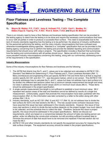
Structural Services, Inc.Floor Flatness and Levelness Testing – The CompleteSpecificationByWayne W. Walker, P.E., F.ACI; Jerry A. Holland, P.E., F.ACI; Cecil L. Bentley, Sr;Eldon (Tipp) G. Tipping, P.E., F.ACI; Rick E. Smith, F.ACI; and Bryan M. BirdwellThere is an industry need to have a floor flatness and levelness testing specification that can be provided tothe testing agency to direct how the testing is to be done and require the necessary communications that haveto occur with all parties in order to produce a successful floor surface. This need is exacerbated due to thelack of industry standards regarding how the testing is to be performed, the absence of industry certificationsfor the personnel performing the testing, and the many industry misconceptions that have confused evenotherwise knowledgeable testing agencies. Attached is a “complete” specification that can be provided to thetesting agency concerning how to perform the testing and provide the detailed reporting and communicationrequirements that should occur with today’s projects. The specification includes a flowchart that summarizeshow the testing and communications with all parties should occur. Below we will try to clear up some of themore prevalent industry misconceptions concerning this testing, along with our commentary addressing someof the requirements in the specification.Industry MisconceptionsSome of the industry misconceptions for floor flatness and levelness are the following:1. The ASTM that directs how the FF and FL values are to be collected and calculated is ASTM E1155 Standard Test Method for Determining FF Floor Flatness and FL Floor Levelness Numbers (Ref. 1).Many architectural and engineering firms just specify ASTM E1155 and think that is all that is required(and/or specify ACI 301 and ACI 117 – see discussion below), which is not correct. This ASTM E1155primarily addresses how to calculate the FF and FL values but does not address how a test surface is tobe divided into different test sections (other than a minimum sample measurement line length and area)nor does it address the specified overall values (SOV) or minimum local values (MLV). These itemsshould be addressed in the project specification.2. A single sample measurement line length is not sufficient to establish a local minimum value. MLVrepresent test section areas of the slab and therefore cannot be defined by results of a single linemeasurement. Unfortunately, papers that promote this misconception have been published with thismisconception (Ref. 2); this information was later corrected by a letter to the editor along with otherarticles (Ref, 3 & 4).3. Industry standards, such as ACI 301 (Ref. 5) and ACI 117 (Ref. 6), do not address how to divide thetest surface (for SOV) into test sections (for MLV). This has caused some confusion because manyhave assumed this issue has been addressed in the industry standards. However, this issue of howmany test sections in which to divide the test surface depends on the project budget, how much data isto be collected, and the schedule time to collect the data. Therefore, because this issue is projectspecific, this issue should be addressed in the project specifications. Below we discuss ourrequirements, which are based on a compromise between the amount of data one testing person cangather, while not affecting the construction schedule, but still providing sufficient localized data tominimize the amount of slab that would have to be removed and replaced if that test section did notmeet the MLV.4. ASTM E1155 and other industry standards do not specify the equipment accuracy for measuring theslab surface changes. The equipment accuracy should be stated in the project specifications.Structural Services, Inc.Page 1 of 4
Specification CommentaryThe attached specification is based on many years of measuring and troubleshooting floor flatness andlevelness issues on different types of projects. The following is commentary and background informationregarding some of our specification requirements.1. We have changed the definition of “test surface” from ASTM E1155’s “entire floor” to “The entire day’sof continuous concrete slab placement”. Contractors have taken advantage of ASTM E1155’sdefinition when placing slab portions with marginally low FF/FL values and then placing slabs withexceptionally high values of FF/FL, such that the average FF/FL will equal or exceed the SOV. Thisissue becomes more pronounced with large buildings, where a floor area as large as 1 million squarefeet or more might have significant slab areas with marginal MLV values of FF/FL. In our specification,by changing the definition of “test surface” this issue is minimized, especially with today’s equipmentwhere daily slab placements of 20,000 sf to 50,000 sf are common.2. As mentioned above, there is no industry standard certification for personnel who perform the testing.We have seen the competency level of the testing personnel vary substantially; this includes sometesting personnel who have “read the equipment manual” and rely on the software to do the testingcorrectly but have little fundamental understanding of the testing procedure. The major testingequipment manufacturers do provide certification training on how to operate their testing equipment andperform the testing. To have a minimum level of testing personnel competency, we have required thetesting personnel to have attended and successfully completed the training provided by themanufacturer of their particular equipment and to submit their certification. In the future, we hope toencourage ACI to develop and offer a F-Number Certification Program and then require ACI CertifiedTechnicians in ACI 301.3. We have added additional reporting requirements above the ASTM E1155 minimal requirement oflisting the FF/FL values in a tabular form. These requirements are necessary to help the contractorimprove and troubleshoot issues when FF/FL values are low. These requirements are:A. Provide a floor plan showing the boundary limits of each test section, along with the locations of thesample measurement lines, such that the deficient areas can be located. The plan should besufficiently accurate to allow the testing to be replicated and data to be verified if necessary.B. Provide a plot or graph of the sample measurement lines, along with the maximum q value (profilecurvature value). This graph and q value can be used to determine if there are anomalies that arebeing “averaged out”, with the result that acceptable FF/FL values are being reported even thoughlocalized problems may be present. Additionally, we take exception to ASTM E1155’s two footexclusion requirement for construction joints by requiring the sample measurement lines to start atthe construction joint; we do this because these locations are often the worst portions of the slabdue to different finishing tools and techniques and also because vehicles, personnel, etc. do notavoid these joints. By starting the sample measure lines at the construction joint, allowsidentification of potential construction joint elevation issues if they are occurring.4. We have added a section concerning notifications. It is very important that the testing agency notify allof the parties if the MLV is not achieved for a specific test section. This notification is to occurimmediately after the test for that section is completed. We have even provided a Work Flowchartshowing how these notifications are to occur during the testing procedure and also the contractor’soptions if a test section is below the MLV. The contractor may choose to do additional testing topossibly limit the amount of slab that has to be removed and replaced.5. We have required that the personnel who will perform the actual testing attend the slab preconstruction meeting. It is important that the testing personnel understand all aspects of thespecification that affect the testing personnel’s work, the importance of timely notifications if testsections MLV values are not being achieved, and who is to be notified.Structural Services, Inc.Page 2 of 4
6. We have required the test section dimensions to satisfy four different requirements and have provided aTest Section Boundary Example demonstrating these requirements. These requirements are based ona compromise between the amount of data one testing person can gather, while not affecting theconstruction schedule, and providing sufficient localized data to minimize the amount of slab that wouldhave to be removed and replaced if that test section did not meet the MLV. Additionally, as noted in theWork Flowchart, the contractor may choose to do additional testing to further divide the deficient testsection to possibly limit the amount of slab that has to be removed and replaced.7. Slab finishing operations are typically performed parallel and perpendicular to column lines; this alsoincludes the orientation of racking systems and vehicular traffic. Therefore, to evaluate any finishingissues with the testing data, we have required the sample measurement lines to be parallel andperpendicular to column lines and not diagonally oriented.References:1.2.3.4.5.6.ASTM E1155 – 14 Standard Test Method for Determining FF Floor Flatness and FL Floor LevelnessNumbersCheek, M. A., 2011, “The Floor Flatness Report”, Concrete International, Jan., pp. 35-39.Birdwell, B. M., and Darrow, D. L., 2012, “Letters”, Concrete International, Mar., p. 6.ACI Staff, 2008, “Concrete Q&A: Rejecting Floors Based on One Sample Measurement Line”, ConcreteInternational, Jul., pp. 83-84.American Concrete Institute (ACI) 301-16 "Specifications for Structural Concrete".American Concrete Institute (ACI) 117-10 "Specification for Tolerances for Concrete Construction andMaterials and Commentary".Wayne W. Walker, P.E., F.ACI, is a Principal and the Director of Engineering Servicesat Structural Services, Inc. He is on several ACI committees and has been a speakerat ACI seminars. He has also published other papers and has developed manycomputer programs to analyze and design slabs and other structures.Jerry A. Holland, P.E., F.ACI, is a Principal, Vice-President and the Director of DesignServices for Structural Services, Inc. He is on several ACI committees, teachesseminars for ACI and the World of Concrete. He has also published other papers and hasmore than 50 years of experience worldwide with the design, construction, andtroubleshooting of concrete slabs other structures.Cecil L. Bentley Sr. is a Concrete Construction Consultant for Structural Services Inc. Hewas the Owner and President of one of the Southeast’s largest concrete contractors. He isan examiner for the American Concrete Institute Concrete Flatwork Finisher/TechnicianCertification Program and a Specialty Commercial/Industrial Flatwork Finisher andTechnician. Cecil has over 50 years of experience troubleshooting concrete failures.Eldon (Tipp) G. Tipping, P.E., F.ACI, is a Principal, Vice-Chairman and Founder ofStructural Services Inc. He is an industry leader, educator and a pioneer in developingplacement, finishing, and monitoring procedures for flat work construction. He is on severalACI committees, teaches seminars for the World of Concrete and other organizations. Tipphas also published other papers and has more than 40 years of design and constructionexperience along with preforming many forensics investigations.Structural Services, Inc.Page 3 of 4
Rick E. Smith, F.ACI, is a Principal, President and a Senior Consultant for StructuralServices Inc. He is a well-known industry leader concerning slabs-on-ground, suspendedslabs and pavements. Rick has developed innovative designs related to the construction,maintenance, repair and polishing of slabs. He is on several ACI committees, teachesseminars for ACI and the World of Concrete.Bryan M. Birdwell is a Principal, Senior Floor & Paving Consultant for Structural Services Inc.He is well-known in the concrete industry for his expertise in the installation, techniques andprocedures of super flat and high tolerance floors. He is on several ACI committees and teachesseminars for the World of Concrete. Bryan is also an examiner for ACI’s Specialty Commercial/Industrial Concrete Flatwork Finisher/Technician Certification Program.Download paper from SSI’s Web site: http://www.ssiteam.com/publicationsStructural Services, Inc.Page 4 of 411OCT18
SECTION 01 43 27 - RANDOM TRAFFIC AREAS FLOOR FLATNESS AND LEVELNESS TESTINGPART 1 - GENERAL1.1 SUMMARYA.Section includes testing and reporting requirements for random traffic floor areas.1.2 RELATED REQUIREMENTSA.Section 03 30 00 - Cast-in-Place ConcreteB.Section 03 35 60 - Concrete Floor Finishing1.3 REFERENCE STANDARDSA.The referenced standards are to be the latest based on this Specification date asshown below.1.ASTM E1155 - Standard Test Method for Determining FF Floor Flatness and FLFloor Levelness Numbers1.4 DEFINITIONSA.The definitions are to be per ASTM E1155, except as follows:1.2.B.Test Surface: The entire day’s of continuous concrete slab placement.Test Section: The subdivision of the test surface where sample measurementlines are used to collect data for the slab’s test surface.Specified overall values (SOV): The composite values of all F-Numbers for the testsections of a test surface.C. Minimum local values (MLV): The minimum F-Number values permitted for anindividual test section.1.5 SUBMITTALSA.Evidence of Qualifications:1.2.B.Provide a certificate verifying the person performing the work is a certifiedtechnician for the floor surface measuring equipment to be used.Testing personnel to have a minimum of 3 years of floor surface testingexperience. Submit list of 3 recently complete projects similar in complexity andinclude project address along with Architect, Structural Engineer, and Contractor’snames and telephone numbers.Equipment:1.2.Provide floor surface measuring equipment data sheets.Provide plan of action if floor surface measuring equipmen
1. The ASTM that directs how the FF and FL values are to be collected and calculated is ASTM E1155 - Standard Test Method for Determining FF Floor Flatness and FL Floor Levelness Numbers (Ref. 1). Many architectural and engineering firms just specify ASTM E1155 and think that is all that is requiredFile Size: 455KBPage Count: 10
