Transcription
Chapter 4NEC & NEMA Standards1This section lists excerpts from industry, national, and international standards. The excerpts are for illustration andeducational purposes. There are often several related tables and information for other configurations and applications.In addition, the standards have added detail and information that applies to all these excerpts. Therefore, anyapplication should refer to the standard, rather than the excerpts.StandardNational Electrical Code (NEC)NFPA 70-2005National Electrical Safety Code(NESC) IEEE C2-2002Motors and Generators (MG1)NEMA MG1-2003OrganizationNational Fire Protection Association,Batterymarch Park, Quincy, MAInstitute of Electrical & ElectronicsEngineers, New York, NewYorkNational Electrical ManufacturersAssociationApplicationElectrical installations in occupanciesElectrical supply stations, overhead,and underground lines.Performanceofmotorsandgenerators
2Electric Power SystemsNEC 240.6(A)1512560020150700DurhamStandard Ampere Ratings for Fuses & Circuit 45503003502000 2500604003000704504000805005000906000100-110-
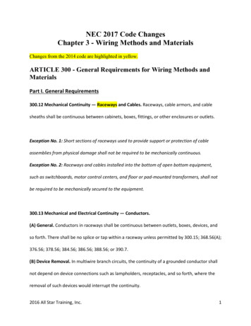
Chapter 4NEC & NEMA Standards3Table 310.16 Allowable Ampacities of Insulated Conductors Rated 0 Through 2000 Volts, 60 CThrough 90 C (140 F Through 194 F), Not More Than Three Current-Carrying Conductors inRaceway, Cable, or Earth (Directly Buried), Based on Ambient Temperature of 30 C (86 F)Temperature Rating of Conductor (See Table 310.13.)60 C75 C90 C60 C75 C90 C(140 F)(167 F)(194 F)(140 F)(167 F)(194 F)Size AWG Types Types RHW, Types TBS, SA, SIS, Types Types RHW, Types TBS, SA,Sizeor kcmil TW, UF THHW, THW, FEP, FEPB, MI, RHH, TW, UFTHHW,SIS, THHN, THHW, AWG orTHWN,RHW-2, THHN, THHW,THW,THW-2, THWN-2,kcmilXHHW, USE,THW-2, THWN-2,THWN,RHH, RHW-2, USEZWUSE-2, XHH, XHHW,XHHW, USE2, XHH, XHHW,XHHW-2, ZW-2XHHW-2, ZW-2COPPERALUMINUM OR COPPER-CLAD 504705606302000CORRECTION FACTORSAmbientFor ambient temperatures other than 30 C (86 F), multiply the allowable ampacitiesAmbientTemp.shown above by the appropriate factor shown below.Temp.( C)( 871–80——0.41——0.41159–176* See 240.4(D).
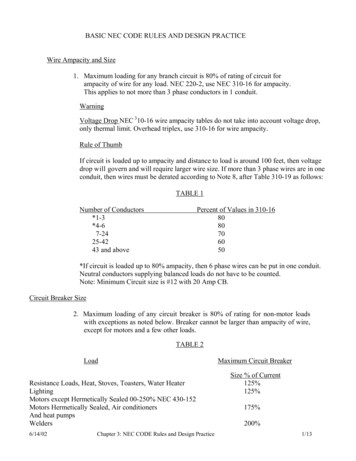
4Electric Power SystemsTable 310.15(B)(2)(a) AdjustmentFactors for More Than Three CurrentCarrying Conductors in a Raceway orCableNumber 031–4041 and abovePercent of Values in Tables310.16 through 310.19 asAdjusted for AmbientTemperature if Necessary807050454035DurhamTable 310.15(B)(6) Conductor Types and Sizesfor 120/240-Volt, 3-Wire, Single-Phase DwellingServices and Feeders.Conductor Types RHH, RHW, RHW-2, THHN,THHW, THW, THW-2, THWN, THWN-2, XHHW,XHHW-2, SE, USE, USE-2Conductor (AWG or kcmil)CopperAluminum 04/0300250350350500400600Service orFeeder Rating(Amperes)100110125150175200225250300350400
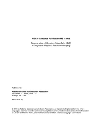
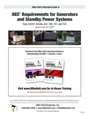
Chapter 4NEC & NEMA StandardsFigure 430.1Article 430 Contents5
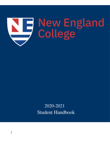
6Electric Power SystemsTable 430.7(B)CodeLetterABCDEFGHJKLocked-Rotor Indicating Code LettersKilovolt-Amperesper Horsepowerwith Locked �8.99CodeLetterLMNPRSTUVKilovolt-Amperesper Horsepowerwith Locked 2.4 and upTable 430.52 Maximum Rating or Setting of Motor Branch-Circuit ShortCircuit and Ground-Fault Protective DevicesPercentage of Full-Load CurrentDual Element Instantaneous Inverse Time(Time-Delay)Trip BreakerBreakerFuseSingle-phase motors300175800250AC polyphase motors other than wound-rotorSquirrel cage300175800250other than Design Benergy-efficientDesign 250Wound rotor150150800150Direct current150150250150(constant voltage)Type of MotorNon-timeDelay FuseDurham
Chapter 4Table 430.91NEC & NEMA Standards7Motor Controller Enclosure SelectionProvides a Degree ofProtection Against theFollowingEnvironmentalConditionsIncidental contact with theenclosed equipmentRain, snow, and sleetSleet2Windblown dustHosedownCorrosive agentsTemporary submersionProlonged submersion3For Outdoor UseEnclosure Type Number13R3S3X 3RX ��X—X—XXXXXFor Indoor UseEnclosure Type Number1244X566P12Provides a Degree of112K 13Protection Against theFollowingEnvironmentalConditionsIncidental contact with theXXXXXXXXXXenclosed equipmentFalling dirtXXXXXXXXXXFalling liquids and light—XXXXXXXXXsplashingCirculating dust, lint,——XX—XXXXXfibers, and flyingsSettling airborne dust, lint, ——XXXXXXXXfibers, and flyingsHosedown and splashing——XX—XX———waterOil and coolant seepage———————XXXOil or coolant spraying—————————Xand splashingCorrosive agents———X——X———Temporary submersion—————XX———Prolonged submersion——————X———1Enclosure type number shall be marked on the motor controller enclosure.2Mechanism shall be operable when ice covered.FPN: The term raintight is typically used in conjunction with Enclosure Types 3, 3S, 3SX,3X, 4, 4X, 6, 6P. The term rainproof is typically used in conjunction with Enclosure Type 3R,3RX. The term watertight is typically used in conjunction with Enclosure Types 4, 4X, 6, 6P.The term driptight is typically used in conjunction with Enclosure Types 2, 5, 12, 12K, 13.The term dusttight is typically used in conjunction with Enclosure Types 3, 3S, 3SX, 3X, 5,12, 12K, 13.
8Electric Power SystemsTable 430.248 Full-LoadCurrents in Amperes, SinglePhase �10115Volts4.45.87.29.813.8162024345680100Table Load Current, Three-Phase Alternating-Current MotorsInduction-Type Squirrel Cage and Wound RotorSynchronous-Type(Amperes)Unity Power Factor* (Amperes)Horse- 115200208230460 575 Volts 23002304605752300power Volts Volts Volts Volts VoltsVoltsVolts Volts Volts �———*For 90 and 80 percent power factor, the figures shall be multiplied by 1.1 and 1.25, respectively.Durham
Chapter 4NEC & NEMA StandardsTable 430.251(A) Conversion Table of Single-PhaseLocked- Rotor Currents for Selection ofDisconnecting Means and Controllers as Determinedfrom Horsepower and Voltage RatingRatedHorsepower½¾11½2357½10Maximum Locked-Rotor Current in Amperes,Single Phase115 Volts208 Volts230 04113102336186168480265240600332300Table 430.251(B) Conversion Table of Polyphase Design B, C, and D Maximum Locked-RotorCurrents for Selection of Disconnecting Means and Controllers as Determined fromHorsepower and Voltage Rating and Design LetterRatedHorsepowerMaximum Motor Locked-Rotor Current in Amperes, Two- and Three-Phase, Design B, C, and D*115 Volts200 Volts208 Volts230 Volts460 Volts575 VoltsB, C, DB, C, DB, C, DB, C, DB, C, DB, C, �——36252900*Design A motors are not limited to a maximum starting current or locked rotor current.These tables for use only with 430.110, 440.12, 440.41 and 455.8(C).9
10Table 8Electric Power SystemsDurhamConductor PropertiesConductorsDirect-Current Resistance at 75 C (167 ty DiameterDiameterAreaUncoatedCoatedormm2 Circularmm in.mmin. mm2 in.2ohm/ohm/ohm/ohm/ohm/ ohm/kcmil)milskmkFTkmkFTkmkFT180.823 16201——1.02 0.040 0.823 0.001 25.57.7726.58.0842.012.8180.823 162070.39 0.015 1.16 0.046 1.06 0.002 26.17.9527.78.4542.813.1161.3125801——1.29 0.051 1.31 0.002 16.04.8916.75.0826.48.05161.31258070.49 0.019 1.46 0.058 1.68 0.003 16.44.9917.35.2926.98.21142.0841101——1.63 0.064 2.08 0.003 10.13.0710.43.1916.65.06142.08411070.62 0.024 1.85 0.073 2.68 0.004 10.33.1410.73.2616.95.17123.3165301——2.05 0.081 3.31 0.005 6.341.936.572.0110.453.18123.31653070.78 0.030 2.32 0.092 4.25 0.006 6.501.986.732.0510.693.25105.261 103801—— 2.588 0.102 5.26 0.008 3.9841.214.1481.266.5612.00105.261 1038070.98 0.038 2.95 0.116 6.76 0.011 4.0701.244.2261.296.6792.0488.367 165101—— 3.264 0.128 8.37 0.013 2.5060.7642.5790.7864.1251.2688.367 1651071.23 0.049 3.71 0.146 10.76 0.017 2.5510.7782.6530.8094.2041.28613.30 2624071.56 0.061 4.67 0.184 17.09 0.027 1.6080.4911.6710.5102.652 0.808421.15 4174071.96 0.077 5.89 0.232 27.19 0.042 1.0100.3081.0530.3211.666 0.508326.67 5262072.20 0.087 6.60 0.260 34.28 0.053 0.8020.2450.8330.2541.320 0.403233.62 6636072.47 0.097 7.42 0.292 43.23 0.067 0.6340.1940.6610.2011.045 0.319142.41 83690191.69 0.066 8.43 0.332 55.80 0.087 0.5050.1540.5240.1600.829 0.2531/0 53.49 105600191.89 0.074 9.45 0.372 70.41 0.109 0.3990.1220.4150.1270.660 0.2012/0 67.43 133100192.13 0.084 10.62 0.418 88.74 0.137 0.3170 0.0967 0.3290.1010.523 0.1593/0 85.01 167800192.39 0.094 11.94 0.470 111.9 0.173 0.2512 0.0766 0.2610 0.0797 0.413 0.1264/0 107.2 211600192.68 0.106 13.41 0.528 141.1 0.219 0.1996 0.0608 0.2050 0.0626 0.328 0.100250127—372.09 0.082 14.61 0.575 168 0.260 0.1687 0.0515 0.1753 0.0535 0.2778 0.0847300152—372.29 0.090 16.00 0.630 201 0.312 0.1409 0.0429 0.1463 0.0446 0.2318 0.0707350177—372.47 0.097 17.30 0.681 235 0.364 0.1205 0.0367 0.1252 0.0382 0.1984 0.0605400203—372.64 0.104 18.49 0.728 268 0.416 0.1053 0.0321 0.1084 0.0331 0.1737 0.0529500253—372.95 0.116 20.65 0.813 336 0.519 0.0845 0.0258 0.0869 0.0265 0.1391 0.0424600304—612.52 0.099 22.68 0.893 404 0.626 0.0704 0.0214 0.0732 0.0223 0.1159 0.0353700355—612.72 0.107 24.49 0.964 471 0.730 0.0603 0.0184 0.0622 0.0189 0.0994 0.0303750380—612.82 0.111 25.35 0.998 505 0.782 0.0563 0.0171 0.0579 0.0176 0.0927 0.0282800405—612.91 0.114 26.16 1.030 538 0.834 0.0528 0.0161 0.0544 0.0166 0.0868 0.0265900456—613.09 0.122 27.79 1.094 606 0.940 0.0470 0.0143 0.0481 0.0147 0.0770 0.02351000 507—613.25 0.128 29.26 1.152 673 1.042 0.0423 0.0129 0.0434 0.0132 0.0695 0.02121250 633—912.98 0.117 32.74 1.289 842 1.305 0.0338 0.0103 0.0347 0.0106 0.0554 0.01691500 760—913.26 0.128 35.86 1.412 1011 1.566 0.02814 0.00858 0.02814 0.00883 0.0464 0.01411750 887—1272.98 0.117 38.76 1.526 1180 1.829 0.02410 0.00735 0.02410 0.00756 0.0397 0.01212000 1013—1273.19 0.126 41.45 1.632 1349 2.092 0.02109 0.00643 0.02109 0.00662 0.0348 0.0106Notes:1. These resistance values are valid only for the parameters as given. Using conductors having coated strands, different strandingtype, and, especially, other temperatures changes the resistance.2. Formula for temperature change: R2 R1 [1 α (T 2 - 75)] where α cu 0.00323, α AL 0.00330 at 75 C.3. Conductors with compact and compressed stranding have about 9 percent and 3 percent, respectively, smaller bare conductordiameters than those shown. See Table 5A for actual compact cable dimensions.4. The IACS conductivities used: bare copper 100%, aluminum 61%.5. Class B stranding is listed as well as solid for some sizes. Its overall diameter and area is that of its circumscribing circle.
Chapter 4NEC & NEMA Standards11Table 9 Alternating-Current Resistance and Reactance for 600-Volt Cables, 3-Phase, 60 Hz, 75 C(167 F) — Three Single Conductors in ConduitOhms to Neutral per KilometerOhms to Neutral per 1000 tive ZEffective Z(Reactance) forResistance forResistance forat 0.85 PF forat 0.85 PF forSizeAll WiresUncoated Copper WiresAluminum WiresUncoated Copper WiresAluminum WiresSize(AWGPVC,SteelPVC Aluminum SteelPVC Aluminum SteelPVC Aluminum SteelPVC Aluminum Steel (AWGor Aluminum Conduit Conduit Conduit Conduit Conduit Conduit Conduit Conduit Conduit Conduit Conduit Conduit Conduit orkcmil) 90.701.11.11.160.1670.2101.611.611.612.662.662.
Chapter 4 NEC & NEMA Standards 3 Table 310.16 Allowable Ampacities of Insulated Conductors Rated 0 Through 2000 Volts, 60 C Through 90 C (140 F Through 194 F), Not More Than Three Current-Carrying Conductors in Raceway, Cable, or Earth (Directly Buried), Based on Ambient Temperature of 30 C (86 F) Temperature Rating of Conductor (See Table 310.13.) 60 C (140 F) 75 C (167 F) 90 C .