Transcription
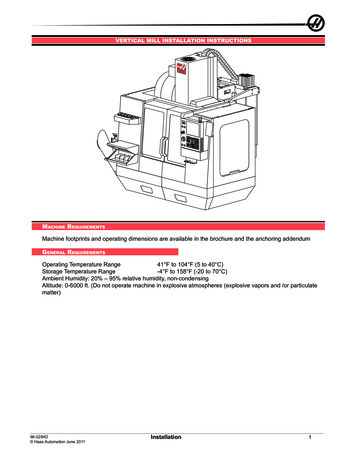
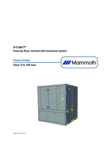
V-Cube Floor-by-floor, Vertical Self-contained SystemProduct CatalogSizes: 9 to 150 tons 2012 Venmar CES Inc.
V-Cube Table of ContentsNomenclature. . . . . . . . . . . . . . . . . . . . . . . . . . . . . . . . . . . . . . . . . . . . . . . . . . . . . . . . . . . . . . 3General Description and Benefits . . . . . . . . . . . . . . . . . . . . . . . . . . . . . . . . . . . . . . . . . . . . . . 4Unit Construction and Components . . . . . . . . . . . . . . . . . . . . . . . . . . . . . . . . . . . . . . . . . . . . 6Controls. . . . . . . . . . . . . . . . . . . . . . . . . . . . . . . . . . . . . . . . . . . . . . . . . . . . . . . . . . . . . . . . . . . 8Engineering Specifications . . . . . . . . . . . . . . . . . . . . . . . . . . . . . . . . . . . . . . . . . . . . . . . . . . 10Application Considerations . . . . . . . . . . . . . . . . . . . . . . . . . . . . . . . . . . . . . . . . . . . . . . . . . . 21Nominal Capacity . . . . . . . . . . . . . . . . . . . . . . . . . . . . . . . . . . . . . . . . . . . . . . . . . . . . . . . . . . 24Unit Dimensions . . . . . . . . . . . . . . . . . . . . . . . . . . . . . . . . . . . . . . . . . . . . . . . . . . . . . . . . . . . 26Dimensional Drawings . . . . . . . . . . . . . . . . . . . . . . . . . . . . . . . . . . . . . . . . . . . . . . . . . . . . . 28Catalog VCES-V-CUBE-PC-1 (April 2012)2
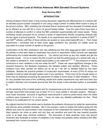
V-Cube NomenclatureModel IndicatorV V-CubeVolume ControlV Variable air volumeC Constant air volumeCondenserN No coolingY Chilled water coolingX Dx without WiSE coil W Dx with WiSE coilZ – Remote condenserA Airside economizerNominal TonnageNumber of Compressors0 Air handlerT Tandem compressorsVoltageF 208-230/3/60K 575/3/60L 220-240/3/60J 380-415/3/50H Heat pumpG 460-480/3/60Heating TypeE ElectricH Hot waterS SteamX No heatFrame SizeS SmallL LargeM MediumT TallControl Panel LocationL – Left handed unitR – Right handed unitVVY0000GSML Venmar CES Inc. 2012. All rights reserved throughout the world.Illustrations cover the general appearance of Venmar CES products at the time of publication and VenmarCES Inc. reserves the right to make changes in design and construction at any time without notice. The following are trademarks or registered trademarks of their respective companies: LonTalk from Echelon Corporation, BACnet from ASHRAE, FANWALL from Huntair, Inc., EPiC and V-Cube from Mammoth, Inc.Catalog VCES-V-CUBE-PC-1 (April 2012)3
V-Cube General Description and BenefitsGeneral Description Fully run tested with water/glycol mixture forsingle piece shipments. Leak tested with water/glycol mixture formodular/sectional shipments. Compact footprint and modular design makeunits ideal for replacement applications aswell as new construction. ETL listed. ASHRAE 90.1 compliant. Available as integrated Dx system with scrollcompressors or air handling units. DDC control system. Factory packaged communicating controlsand variable frequency drive (VFD).Flexible DesignThe V-Cube is available in capacities ranging from9 to 150 tons in order to match the requirementsof a broad range of areas and space loads. Unitsoffer a tremendous configuration flexibility tomeet the requirements of your project. Water cooled Dx system with or without waterside economizer. Air handling units with chilled water cooling. Available air cooled Dx system with remotecondensing. Available for water source heat pump applications. Available in fluid/dry cooling applications. Available in air cooled chiller applications.A factory integrated controller offers flexibility forstand alone operation or optional communicationwith common, industry recognized building automation systems.Ideal for New Construction and TightSpacesV-cube is designed for quiet operation and compact design, perfect for floor-by-floor applications. The packaged design, complete with optionalVFD and factory integrated communicatingcontrols, reduces field labor. A compact footprint allows easy installationin tight mechanical rooms. Small frame units can be disassembled intosections to fit through a standard 3 footdoor, with electrical quick connects between sections.Catalog VCES-V-CUBE-PC-1 (April 2012) Built in electrical disconnects reduce fieldlabor and installation costs.High EfficiencyOperating components are selected to optimizeefficiency, to conserve energy and significantly reduce operating costs. The factory mounted VFD is standard witheach unit to optimize fan energy consumption. Optional digital scroll lead compressor provides superior part load operation (to 10%load) and avoids the need for hot gas bypass.Quiet OperationExtremely quiet operation allows units to beplaced adjacent to occupied spaces increasing theleasable area. Heavily attenuated equipment room wallsmay be eliminated, reducing installed costs. FANWALL TECHNOLOGY provides soundstudio quality quiet fan operation and canhelp avoid costly attenuation. Scroll compressors operate smoothly and quietly.Superior Comfort and Indoor AirQualityThe V-Cube design and a variety of filtration options provide occupants superior comfort and indoor air quality (IAQ). Standard double wall construction and dualsloped stainless steel drain pan help preventmicrobial growth and provide a surface easilycleanable during routine maintenance. Multiple filter options include up to MERV15, 4” final filters with 4” prefilters or MERV14, 12” final filters with 4” prefilters. Quiet fan and compressor operation contributes to comfortable space conditions.Easy Maintenance and Service Unit tooled access panels allow easy removaland replacement for routine maintenanceand service. Factory installed filter racks enable easy filterreplacement and help reduce installed costs.FANWALL system eliminates belt, sheaves,bearing and motor maintenance. Cleanable in place shell and tube condenser,double wall construction and dual sloped,stainless steel drain pan encourage routinemaintenance for peak performance.4
Durable and Reliable OperationV-Cube is designed for long lasting operation withminimum downtime. Fan redundancy provided bythe FANWALL system allows the unit to operateCatalog VCES-V-CUBE-PC-1 (April 2012)at nearly full capacity with one fan down. Operating components are selected for durability andlong life.5
V-Cube Unit Construction and ComponentsCabinetRefrigeration SystemThe cabinet walls, access doors, roof and floor areconstructed of an Integrated Thermal Break Framing (ITF) system with 3” R12.9 insulation,welded base frame and floor membrane, providing an industrial grade flexible and tough air andwater-tight seal. All openings through the casingare grommeted.Each refrigerant circuit is complete with liquid linemoisture indicator and thermal expansion valvecomplete with an external equalizer line. Units aredesigned for use of R410a refrigerant. Each refrigeration circuit consists of a scroll compressor,(shell and tube) heat exchanger and airside coil.Water source heat pump units include a reversingvalve. The reversing valve is energized in the cooling mode and is fail safe to the heating mode.Cabinet allows disassembly of the unit into threesections: compressor and heat exchanger section,blower section and coil section, as well as mixingbox, discharge or inlet plenum (where applicable).Units are provided with a top discharge as standard with rear return. Optional side or front discharge are available. Units with cooling coils havea dual sloped stainless steel drain pan.Access to controls, compressors and supply fans isthrough access doors with tooled access locks andlift tabs. Motor access and blower wheel removalcan be achieved through the access doors on thefront of the unit.The ETL listed control panel includes contactors,motor protectors, relays and transformers. A disconnect in the panel is provided for connectingbuilding power to the unit. All branch circuits areindividually protected and include a low voltagecontrol circuit transformer. Motors and compressors are protected on all phases. Optional phaseand brown out protection shuts down all motorsif the electrical phases are more than 10% out ofbalance on voltage, voltage is more than 10%under design or on phase reversal. The EPiC System controller is factory installed and wiredand is capable of operating on a stand alone basisor with common, industry leading protocols. Thecontrol system is pre-wired so that remotestart/stop can be accomplished through the building BMS system via contact closure.Each circuit is equipped with a low and high refrigerant pressure switch with manual reset,Schrader valves on both the high and low pressuresides and a liquid line filter drier. A liquid line siteglass is standard for shell and tube heat exchangerunits. Refrigerant circuits incorporate refrigerationgrade seamless “Type L” copper tubing.The compressor is a scroll type with thermal overload protection. The unit comes complete withmultiple refrigeration circuits where each compressor is no larger than 15 horsepower. The optional digital scroll compressor is capable ofmodulation from 10%–100% of its capacity. Thecompressors are mounted on rubber vibration isolators and are located in a service compartmentthat can be accessed without affecting unit operation. Access is through a tooled access panel.The shell and tube heat exchangers are mechanically cleanable and provided with removable endbells with Victaulic fittings. The condenser isequipped with a large liquid sub-cooler, designed,tested and stamped in accordance withANSI/ASME Boiler and Pressure Vessel Code for arefrigerant side working pressure of 600 psig.Shell and tube condensers are provided with aspring loaded pressure relief valves.The filter box assembly is removable. Filters areside loaded from the same side as the electricalaccess door. A 2” pleated media panel filter isstandard. Options include a 4” pleated filter witha MERV 13 rating. A 2” prefilter is also available.All single piece units are factory assembled andtested including leak testing of the coils, pressuretesting of the refrigeration circuit and run testingof the completed unit. Multiple piece or modularunits are leak tested within the factory and fittedwith a nitrogen holding charge for shipment.Catalog VCES-V-CUBE-PC-1 (April 2012)Operating components are selected to optimizeefficiency and maximize performance.6
The air coil is designed for use with R410a refrigerant and constructed of ½” rifled copper tubesmechanically bonded to lanced aluminum fins.Coils have various combinations of row and facesplit circuitry depending on the number of refrigeration circuits present within the unit.Optional coils include: economizer, chilled water,hot water, steam, electric heat and refrigerantreheat.Fan SectionThe fan section consists of the fans, motors, variable frequency drives (VFD) and discharge outlet.Airside components are separated from the compressor section to limit noise transmission fromthe compressor. Units incorporate either singleplenum fans or FANWALL TECHNOLOGY with anarray of direct drive, dynamically balanced, airfoilshaped blade plug fans.FANWALL TECHNOLOGY provides sound studioquality quiet operation and provides superior redundancy to avoid system downtime.Motors are premium efficiency totally enclosedwith sealed and locked bearings and NEMA ratedframe designed for quiet operation. Motors aredesigned for use with VFDs and include bearingprotection rings to reduce bearing frosting, pittingand bearing failure caused by VFD induced voltages on the motor shaft.Units are provided with a top discharge as standard with rear return. Optional side or front discharge are available.Optional VFD with bypass is factory mounted andwired. Redundant VFD with auto-changeover isalso available for mission critical applications.Catalog VCES-V-CUBE-PC-1 (April 2012)7
V-Cube ControlsThe standard factory integrated EPiC Systemcontroller provides control flexibility that can beeasily customized to meet any sequence of operation needs. It is fully capable of operating in a100% stand alone mode or can connect to aBuilding Automation System (BAS) using any oftoday's four leading protocols: BACnet , Modbus , N2 and LonTalk . The base controller provides ample input/output capacity, plus support foran expander board if additional I/O capacity is required. The controller provides these key features: Built in support through a Rnet port for control's custom configurable keypad/displayunit, BACview6 (4 line by 40 character perline display), for intelligent sensors. For variable air volume (VAV), constant volume(CAV) and make-up air (MAU) applications.Used with applications having options requiring a greater number of outputs and inputs. As additional options are added an I/O 8160expander will be needed. I/O point count: 6 digital outputs, 12 universal inputs and 6 analog outputs. I/O pointscan be increased by use of an optional I/OFlex Expander. Optional built in protocol support: BACnet(ARCNET, MS/TP, and PTP modes), Modbus(RTU and ASCII modes supported), N2 orLonTalk. Powerful, high speed 16-bit microprocessorwith 1 MB Flash memory and 1 MB of battery backed RAM.InputsPoint6126 ControllerUI #1 PulseUI #2UI #3DescriptionBMS SAT reset, or BMS DSP reset (alternate) or humidity sensor #2(RA, for special comparative enth)BMS DSP reset (common duct slave) or humidity sensor #1 (RHfeedback or OA for special enth)Spare, or IAQ (CO2, OA measurement) or humidity (control feedback)UI #4Spare, or filter #2 static pressure or BMS DSP/SAT reset (alternate)UI #5Spare, or filter #1 static pressure or dirty filter switch #1UI #6UI #7UI #8UI #9Spare or building static pressureDuct static pressure (VAV) or airflow switch (CAV)RTD/Therm/Dry contact, 0–10 VDC,Cooling coil leaving air temperature or mixed air temperature (mon0–20 mAitoring)Condenser water temperatureUI #10Outside air temperatureUI #11Entering air temperature or return air temperatureUI #12RnetSupply air temperatureLocal access portCatalog VCES-V-CUBE-PC-1 (April 2012)Room air temperature/setpoint/override (RS-Plus)8
InputsPoint8160 ExpanderDescriptionDI #1System switchDI #2Emergency shut-downDI #3Remote startDI #4DI #5DigitalEconomizer lockoutCooling lockoutDI #6Heating lockoutDI #7Supply fan statusDI #8Condensate overflow, or water leak (CW) or return fan statusDI #9High staticLow staticVFD in bypassUI #10Compressor fault #1Compressor fault #2Compressor fault #3Compressor fault #4Compressor fault #5Compressor fault #6UI #11UI #12UI #13Heating fault #1SA RH high limitTherm/Dry contact, 0–5 VDC (Multi- SparePlexed DI’s)Spare or room air temperature #1 setpoint (Tstat) or slab temperatureUI #14Spare or room air temperature #1 (Tstat)UI #15Circuit #2 head pressureUI #16Circuit #1 head pressureOutputsPointsUO #2DescriptionDigital scroll (1–5 VDC), or Cooling source (CW coil), or TCHGBP orHGRH control signalHeating source control signalUO #3Economizer control signal (WiSE or AISE)UO #16126 Controller4–20 mA, 0–10 VDCUO #4UO #6WiSE bypass, or head pressure or condenser fan VFD control signalReturn fan VFD, or humidifier control signal or common duct coordination speed signal outSupply fan VFD control signalDO #1Spare or heating call #4UO #50–10 VDCDO #2Start condenser pump, or reversing valve or start return fanDO #3Field-link (MWU, NSB or open min OA)DO #4120 VAC Form CCommon alarmDO #5Heating call #3 or hot gas reheat call #2DO #6Heating call #2 or hot gas reheat call #1Points8160 ExpanderDescriptionDO #1Supply fan start/stopDO #2Heating call #1DO #3Cooling call #6 or condenser fan VFD start/stopDO #4DO #5120 VAC Form ACooling call #5 or unload screw compressorsCooling call #4 or load screw compressorsDO #6Cooling call #3DO #7Cooling call #2DO #8Cooling call #1Catalog VCES-V-CUBE-PC-1 (April 2012)9
V-Cube Engineering SpecificationsGeneralProvide factory fabricated air handling units withcapacity as indicated on the schedule. The unitsconsist of factory assembled components asshown on drawings, including but not limited tofan and motor assemblies, plenums, filters, drainpans, wiring, controls and other accessories asoutlined in the schedule, enclosed in a single ormultiple piece casing as shown on the mechanical drawings. Units shall be stand alone controlled, except where noted, with all controldevices provided and wired for single pointpower connection by the manufacturer unlessotherwise outlined in the schedule. Units shallhave overall dimensions as indicated and fit intothe space available with adequate clearance forservice as determined by the Engineer. Tags anddecals to aid in service or indicate caution areasshall be provided. Electrical wiring diagrams andInstallation, Operation and Maintenance Instructions Manual (IOM) shall be attached to the control panel access doors within each unit. Unitsshall be UL or ETL listed. Units shall be shipped inone piece or shall be split for shipment to accommodate freight as required, as shown on mechanical drawings.Unit Base and FloorUnit perimeter base shall be completely weldedand constructed from 4” structural tubing andshall accommodate concrete pad installation asshown on drawings (bolted or riveted bases arenot acceptable). Unit base shall be internally insulated with 4” [102 mm], R13.3 fiberglass. Unitbase floor shall be constructed from four-breakformed steel panels, made from 14 gauge hotrolled steel (HRS). Floor panels shall be welded toeach other, creating “I” beams at each floor paneljunction. Floor panel junctions shall be located at14” increments (maximum) or less, in order toprovide floor rigidity and support as required forinternal components. Unit floor panels shall bewelded to perimeter base frame steel tubing. Unitfloor shall be factory covered with top coat industrial grade membrane to ensure air and watertightness as well as walk-on grip. Floor membraneshall be high performance, sprayed, plural component pure polyurea elastomer, based on amineterminated polyether resins, amine chainextenders and prepolymers. Floor membrane shallbe flexible, tough, resilient monolithic membraneCatalog VCES-V-CUBE-PC-1 (April 2012)with good water and chemical resistance, andshall resist to temperatures up to 250ºF. Floormembrane materials shall be free of solvents andVOCs, shall be suitable for use in compartmentshandling conditioned air and shall comply withthe requirements for the Standard for Heatingand Cooling Equipment, ANSI/UL 1995, third edition, dated 02/18/2005, section 5.10 and section18. Unit base under liners shall be made of 24gauge galvanized steel. Base frame constructionshall include two-stage thermal break, using gasket between base floor framing and under linersunderneath and floor membrane on top. Singlewall floor construction with glued and pinned insulation and no sub-floor is not acceptable; noninsulated floor construction is not acceptable.Floor constructions which are not air and watertight are not acceptable. Entire base frame is tobe painted with a phenolic coating for long termcorrosion resistance. Base frame shall be attachedto the unit at the factory. When rigging, baseframe deflection shall be less than 1/360 of theunit length. All major components shall be supported by the base without sagging or pulsating.Unit CasingUnit wall and roof rigid frame shall consist of 16gauge prepainted galvanized formed steel cornerposts and 16 gauge G90 galvanized formed steel(1” x 2”) intermediate frame posts, providing stable construction allowing for removal of any panelwithout affecting unit structural integrity. Unitswithout framed type of construction are not acceptable. Exterior casing panels shall be attachedto the gasketed (1” x 2” [25 mm x 51 mm]) steelframe with corrosion resistant fasteners. Air handling unit casing shall be of the “no-throughmetal” design. Casing shall incorporate insulatingthermal breaks as required so that, when fully assembled, there is no path of continuous unbrokenmetal to metal conduction fr
Apr 01, 2012 · lon Corporation, BACnet from ASHRAE, FANWALL from Huntair, Inc., EPiC and V-Cube from Mammoth, Inc. VVY 000 0 GS ML Model Indicator V V-Cube Volume Control V Variable air vo