Transcription
(IJACSA) International Journal of Advanced Computer Science and Applications,Vol. 9, No. 7, 2018Intrusion Detection and Prevention Systems as aService in Could-based EnvironmentKhalid AlsubhiHani Moaiteq AlJahdaliFaculty of Computing and Information Technology Faculty of Computing and Information Technology RabigKing Abdulaziz University, Jeddah, Saudi ArabiaKing Abdulaziz University, Jeddah Saudi ArabiaAbstract—Intrusion Detection and Prevention Systems (IDPSs)are standalone complex hardware, expensive to purchase, changeand manage. The emergence of Network Function Virtualization(NFV) and Software Defined Networking (SDN) mitigates thesechallenges and delivers middlebox functions as virtual instances.Moreover, cloud computing has become a very cost-effectivemodel for sharing large-scale services in recent years. Featuressuch as portability, isolation, live migration, and customizability of virtual machines for high-performance computing haveattracted enterprise customers to move their in-house IT datacenter to the cloud. In this paper, we formulate the placement ofIntrusion Detection and Prevention Systems (IDPS) and introducea model called Incremental Mobile Facility Location Problem(IMFLP) to study the IDPP problem. Moreover, we proposea novel and efficient solution called Adaptive Facility Location(AFL) to efficiently solve the optimization problem introduced inthe IMFLP model. The effectiveness of our solution is evaluatedthrough realistic simulation studies compared with other popularonline facility location algorithms.Keywords—Facility Location Problem; Intrusion detection andPrevention Systems; Cloud ComputingI. I NTRODUCTIONCloud computing has become a cost-effective model forsharing large-scale services in recent years. Its success is dueto the attractive features offered by the underlying virtualization concept, including portability, isolation, live migration,and customizability of virtual machines. Popular examples ofcloud-based services are Microsoft Azure, Google AppEngine,and Amazon Elastic Computing Cloud (EC2). Cloud servicesare generally categorized into three areas: Software as a Service (SaaS), Platform as a Service (PaaS), and Infrastructureas a Service (IaaS). In SaaS, a third-party provider hostcustomer’s application over the Internet (i.e., Rackspace andSAP Business ByDesign). In PaaS model, both hardware andsoftware are provided and hosted by third-party (i.e., GoogleApp Engine and Microsoft Windows Azure). Finally, IaaSrefer to providing virtualized computing resources, usually interms of VMs (i.e., Amazon EC2, GoGrid and Flexiscale).Intrusion Detection and Prevention Systems are an essentialdefensive measure against a range of attacks [44, 47]. Inenterprise networked system, IDPSs examine packets sentover networks and trigger alerts when malicious content isdiscovered and defend against attacks when prevention modeThis project was funded by the Deanship of Scientific Research (DSR) atKing Abdulaziz University, Jeddah, under grant no. J724-611-38. Theauthors, therefore, acknowledge with thanks DSR for technical and financialsupport.is active. Most issues regarding security in cloud systems areinherited by the current enterprise network [34]. Traditionaldistributed IDPSs are best practice in providing security forlarge scale networks. However, the deployment of distributedIDPSs in cloud systems raise many challenges due to thediversity of its services and the complexity of its infrastructure[43].Network Functions Virtualization (NFV) [1] [2] promisesa reprive from the vertically integrated hardware middleboxmodel followed for decades, by advocating the use of softwareNetwork Functions (NFs) running on commodity hardware.This means a reduced acquisition and operational costs, flexible programability, and easier management [31] [42]. Anotherorthogonal idea is the Software Defined Networking (SDN)that advocates flexible programability in the network. Thisis done by the separation of the control-plane from the dataplane and centralized logical control of the network. SDNsimplifies the overall management of the network by allowingdeeper programability of the networking devices. LeveragingSDN in environments where NFV are used can leads toseveral interesting use cases. The high precision control offorwarding elements (switches) provided by SDN can be usedto orchestrate traffic patterns between various appliances andNFVs across a data center [22]. In recent years, the cloudhas become a mature platform for deploying scalable andcost effective services. With huge growth forecasts, the publiccloud industry has grown to become a multi-billion dollarindustry [6]. Combining the agility of the cloud with theflexibility of Virtualized Network Functions (VNFs) and thefine-grained control of SDN can bring about a new class ofcloud based services for IDPSs [13].In this paper, we introduce a model in which infrastructureproviders support Vritual Intrusion Detection and PreventionSystems (IDPSs) as a Service (IDPSaaS) by leveraging NFV,SDN, and cloud. IDPSaaS services can be enabled or disabledfor tenant’s Virtual Machines (VMs) on their demands and canbe scaled up or down to cope with their service workloads.Moreover, the deployment of multiple IDPS instances of anetwork functions motivates an interesting challenge, whichwe call Intrusion Detection and Prevention Systems Placementproblem (IDPSP). In order to study the IDPSP problem,we propose Incremental Mobile Facility Location Problem(IMFLP) based on the online facility location problem. IMFLPtakes into account the online actions, such as live migrationsin cloud, which are ignored in almost all of the existingwww.ijacsa.thesai.org271 P a g e
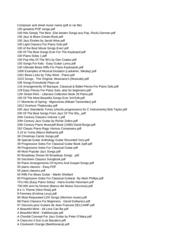
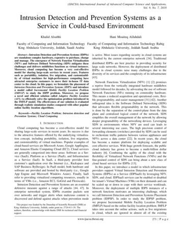
(IJACSA) International Journal of Advanced Computer Science and Applications,Vol. 9, No. 7, 2018models [21]. To the best of our knowledge, it is the first timethat the online version of facility location problem has beenused to study placement of IDPS. Furthermore, we presentan efficient solution for the optimization problem definedin this model called Adaptive Facility Location (AFL). Thissolution by employing online actions, such as migrations andswitches, adjusts the placement of IDPS instances to efficientlyadapt to changes in service demands. The effectiveness ofour solution is evaluated though realistic simulation studiesand empirically compared with several popular online facilitylocation algorithms.The remainder of this paper is organized as follows. Insection II, we formulate the IDPSP problem and present theIMFLP model for studying this problem. We present AFL insection III and conduct experiments to evaluate this algorithmin section IV. The related works are discussed in section V.Finally, we conclude and discuss about future works in sectionVI.II. P ROBLEM F ORMULATIONAs mentioned before, the placement module receives anevent of an arrival or leaving of a demand, and by informationand functions supported by the management module, adjuststhe placement of facilities. In this section, we introduce theIntrusion Detection and Prevention System Placement problem(IDPSP) in section II-A. In section II-B we formally defineour model of facility location problem that can be used formodeling the IDPSP problem.A. Intrusion Detection and Prevention System PlacementProblem (IDPSP)Without loss of generality, we introduce this problemthrough an example. Suppose that an infrastructure provideroffers a IDPSaaS service. From the client’s point of view, herVMs can be installed any time, and the IDPSaaS service can berequested and enabled for her VMs at any moment. Moreover,VMs are different and have various service workload onthe IDPS instances (IDPSInst). Let call each unit of VM’sworkload as a demand. Thus, we can view the problem asdynamic demands that should be served by multiple IDPSInsts.From the view point of the infrastructure provider, enablingthis service incurs certain amount of the installation, operational, and management costs. The installation cost includesthe cost of resource consumption of a host machine on which aIDPSInst is installed, and the cost of certain messages betweenthe controller and the host. In our system, all IDPSInsts aresame, and therefore the installation cost is same for all IDPSInsts. The operational cost consists of the traffic processing delaycost, and the cost of steering the traffic to the IDPSInst andthen to the destination VM. It can be shown that the cost ofsteering the traffic is related to the distance between IDPSInstand the VM. Finally, the management cost includes the costof certain statistics collection and syncronization messagesbetween the controller and the IDPSInsts. The managementcost is related to the cost of shortest path between thecontroller(s) and the IDPSInst. Optimizing the managementcost is similar to the placement of SDN controllers [8] [29],and is outside of the scope of the current paper.Considering Figure 1, suppose that a VM exists on hosta. As illustrated in Figure 1(a), when there is no IDPSInstenabled (the service-less case), the internet traffic travels theshortest path from the core switch r to the host a with anintermediate switch m. Let d(r, a) represents the cost of theshortest path between r and a. In the service-less case, thecost of traffic traversal is d(r, a) d(r, m) d(m, a). Onthe other hand, as shown in Figure 1(b), when the IDPSInstis installed on a host b (the IDPSInst enabled case), extracosts are paid. Certain amount of b’s resources are allocatedto the IDPSInst and certain controlling messages from thecontroller are exchanged with the host b (the installation cost).This installation cost is independent of the where IDPSInstsare located, and only depends on the number of IDPSInsts.Moreover, IDPSInst adds certain processing delay time t, andthe traffic travels a longer path (the operational cost). Delaytime t is independent of where the IDPSInst is placed andrelated to how much traffic is assigned to. Additionally, thetraffic is steered from core switch r to host b, and from hostb to the host a. In this case, the cost of the traffic steering isd(r, b) d(b, a) d(r, m) 2d(m, b) d(m, a) (We assumethat the shortest path cost is symetric). By deducting the costof service-less case, the extra cost in the IDPSInst enabledcase is 2d(m, b). Because a and b are in the same level(host level) d(m, b) d(m, a), and therefore the extra costis 2d(m, b) d(m, b) d(m, a) d(a, b), which is the costof shortest path between host a containing IDPSInst and hostb containing the VM.There is another complexity dimension that makes theproblem even more complicated. Assignments of demands tothe IDPSInsts are not irrevocable decisions, and demands canbe reassigned to other IDPSInsts. However, these reassignments are not free of charge and associated with certain costsrelated to the routing reconfiguration and transferring sourceIDPSInst’s internal state to the destination IDPSInst [22].Furthermore, after assigning more demands to an IDPSInstduring the time, this IDPSInst can migrate to another locationin order to minimize its distance to the VMs and subsequentlyreduce the operational costs; however, migrations are not freeand are associated with certain cost.rrmmVMVMab(a) Service-Less Casewww.ijacsa.thesai.orgaIDPSb(b) IDPSInst Enabled CaseFig. 1. The comparison of the traffic path272 P a g e
(IJACSA) International Journal of Advanced Computer Science and Applications,Vol. 9, No. 7, 2018Any model describing this problem must consider thedynamic nature of the problem, optimizing the installationand operational cost of the IDPSInsts, and possibility ofassignments switches and IDPS migrations. B. Increamental Mobile Facility Location ModelIn this section, we introduce a new model of facility locationproblem called Incremental Mobile Facility Location Problem (IMFLP) to study the IDPSP problem. Before describingour model, we briefly describe why a new model of thisproblem is needed to be formulated. The details of otherexisting models will be discussed in the section V-B.The offline model of facility location problem has beenstudied comprehensively in the literature [15, 9, 40, 16].Unfortunately, it cannot describe IDPSP, becuase this modelrequires demands and their locations to be known in advanced, but in IDPSP, VMs are installed at any momentand subsequently their demands are not known beforehand.In other words, assignments of demands to IDPSInsts aredone without knowledge about the future demands. Hence,the online model of this problem should be used. However, theexisting online models in the literature (as will be discussedin section V-B) are not representative for our problem, thuswe design a new model of this problem. Our IMFLP modelrelaxes certain constraints of the these models and resolve theirlimitations in describing IDPSP problem to model migrationsand assignments switches.We describe our model of facility location problem by defining the space and metrics, facilities, demands, and allowedactions.Space and metrics. Given a connected weighted graphM (V, E) representing the architecture of the data centernetwork, where V denotes the set of nodes (switches or hosts),and E : V V R represents the set of network links.Vhosts V represents host nodes in which demands andfacilities can reside. The shortest path between two nodesp, q V is denoted by d(p, q). We also use the notationof d(V 0 , p) to denote the shortest path between the closestnode in a subset V 0 V to a node p V . Moreover, letB(p, r) {q Vhosts , r R d(p, q) r} indicates thenodes within distance r to the node p (the points that lie insideor on the ball with center p and radius r). We assume that thedistance metric is symetric and satisfies triangle inequality.Facility. In IMFLP, a facility represent a VNF instance andis uncapacitated. The location of a facility z in the space isidentified by the γ(z) Vhosts . We use term open or installinterchangeably for the installation of a facility. Besides, thenotation C(z) represents a set of demands that are assignedto a facility z (z’s cluster).Demand. A demand u denotes a unit of service workloadof a VM. Similar to a facility, the location of a demand isgiven by γ(u) Vhosts , which is equal to the node that VMresides. We use term arrive to denote that a new demand froma VM should be served. We also assume that each VM has acorrect number of demands.Allowed Actions. In IMFLP following actions are allowed: A facility can be opened in any node p Vhosts at anytime by paying the installation cost f R . A facilityalso can migrate to another location with the migrationcost k R . we assume that k f . Moreover, a facilitycan be closed at any time, and its installation cost isrefunded. However, if any demand is assigned to thatfacility, they should switched to a new facility and foreach switch, the certain amount of cost as described nextis payed.A demand is allowed to arrive and leave at any time inany node p Vhosts . The migration of a VM can bemodeled by leaving of its demands and their arrivals inthe destination node. Furthermore, a demand assignmentcan be switched to another facility by paying the switchcost h R . We assume that h k f .Additional notation. Please note, for a demand u and afacility z, instead of d(γ(z), γ(u)) we simply use d(z, u) torepresent their distance. In addition, we define (x y) max(0, x y) for x, y R .The model is described as follow. Upon arrival or departureof a demand ut at time t (the input of our model), a newfacility ω or a set of facilities can be opened, closed, ormigrated. Likewise, a subset of demands can be switched toother facilities. Therefore, the following costs are defined attime t:1) Total installation cost (Cins ) is the cost of installationof a set of facilities Ft at time t.Cins Ft f(1)Here, Ft denotes the number of facilities.2) Total operational cost (Cop ) represents the operationalcost of a set of facilities F .X XCop gd(u, z)(2)z Ft u C(z)As shown in equation 2, this cost is defined based onthe shortest paths between facilities and their assigneddemands.3) Total migration cost (Cmig ) is the cost of migration ofa set of facilities since start time until time t.Cmig kt XX γi 1 (z) 6 γi (z) (3)i 2 z FiIn equation 3, γi (z) represents the location of facility zat time i. Please note that term γi 1 (z) 6 γi (z) is 1if γi 1 (z) 6 γi (z), otherwise it is 0.4) Total switch cost (Csw ) denotes the switch cost of a setof demands Lt at time t.Csw ht XX φi 1 (u) 6 φi (u) (4)i 2 u LiHere, φi (u) represents the facility that demand u isassigned to at time i. Note that φi 1 (u) 6 φi (u) isequal to 1 if φi 1 (u) 6 φi (u), otherwise it is 0.www.ijacsa.thesai.org273 P a g e
(IJACSA) International Journal of Advanced Computer Science and Applications,Vol. 9, No. 7, 2018The objective of the optimization problem in the IMFLPformulation is to minimize the overall cost (Coveral ) as definedin equation 5.Coveral Cins Cop Cmig Csw P otins (p) g. d(Ft 1 , ut ) d(p, ut ) X (d(φ(v), v) d(p, v) h) v Lt 1(5)The IDPSP problem can be reduced to the optimizationproblem defined in the IMFLP model. This optimizationproblem is NP-hard (facility location problem is NP-hard,and our online model is even more complicated than originalproblem). Motivated by this observation, we developed anonline algorithm for IMFLP model.III. A DAPTIVE FACILITY L OCATION (AFL)In this section, we propose our solution, Adaptive FacilityLocation (AFL), for the optimization problem introduced inthe IMFLP model. We introduce two novel algorithms thatuse the simple idea of profit and loss for handling a demandarrival and a demand departure.However, before describing our model, we justify our selection over other candidate approaches. In the area of SDN, someof ubiquitous approaches for modeling the optimization problems are the linear programming [28, 49], simulated annealing[48, 36], and Markov approximation [30, 41]. The linearprogramming approach solves an offline problem, and is notdescriptive enough to model the dynamicity and online natureof these kind of problems. In addition, the linear programmingis known that is slow. To deal with the dynamic nature ofthese optimization problems, simulated annealing and markovapproximation are used. In the simulated annealing techniques,at each step again an offline problem is defined, and knownto be trapped in the local minimums, and might suffer fromthe bad initial state. Finally, Markov chain techniques mightalso affected from bad initial state and slow convergence tothe steady state.A. Demand ArrivalTwo functions namely, migration potential and installationpotential are defined to represent how far facilities and assignments of demands are from the optimal or stable configuration,and how much profit is gained by the installation or migrationof a facility, respectively. Then by comparing with the cost ofcertain actions (the loss), AFL decides which action is applied.Installation potential function (P otins ) is defined asequation 6. This function represents how much of the currentcost can be reduced by installation of a facility at a nodep Vhosts . In this equation, ut denotes a new arrived demandat time t. Ft 1 and Lt 1 represent a set of opened facilitiesand demands at time t 1 just before arrival of ut . The firstterm computes the profit of the situation where ut is assignedto a facility that can be installed at node p against when utis assigned to the closest facility in Ft 1 . The second termshows that if some demands are switched to a facility thatcan be installed at node p, how much the operational cost ofrelated to these demands will reduce (recall that each switchincurs switch cost h).(6)Migration potential function (P otmig ) is defined in equation 7. This function describes how much the migration of afacility z from its current location to a node p reduces its totaloperational cost when a new arrived demand ut is assigned toz as well. This function can be interpreted in another senseas well. Each demand v Ct 1 (z) attempts to reduce itscost by pulling facility z toward its location γ(ut ). If a newarrival demand ut will be assigned to z, ut also tries to pullfacility z toward itself. The potential function P otmig (z, p)represents how much z becomes more stable by migrationform γ(z) to p. In other words, z is close enough to eachdemand v Ct 1 and more closer to ut in comparison tofacilities Ft 1 including z itself. P otmig (z, p) g. d(Ft 1 , ut ) d(p, ut )X (7) d(z, v) d(p, v)v Ct 1 (z)Algorithm 1 shows AFL algorithm (for the sake of simplicity, we drop t subscript, but we insist that the presentedalgorithm is run at time t). By exploiting the aforementionedfunctions, AFL attempts to improve the current placement offacilities and current assignment of demands. Upon arrival ofa new demand u, AFL considers three actions:1) Installation action: Installation of one new facility inthe best place with the best possible switches.2) Migration action: Migrating one of the existing facilities (the best one) without any demand switches andassigning u to this facility.3) Assignment action: Assigning u to the nearest existingfacility.As shown in algorithm 1, AFL computes the installation andmigration potentials. By comparing the the computed values,AFL applies the best action. For the installation action, AFLcalculates the installation potential P otins for every point pin the distance of f from u (B(u, f )). AFL selects the bestpoint ωins , which maximizes the P otins . If AFL decided toapply this action, it switch the neighbor demands to ωins , ifthis switches reduce the service cost and the deducted servicecost is bigger than switch cost h.For the migration action, AFL computes the migrationpotential P otmig for each facility z and for each point p in thespace Vhosts . Eventually, AFL chooses the best facility ωmigto migrate to point ρ that maximizes P otmig .Ultimately, AFL decides which action is applied. Theinstallation action is considered first. If it is beneficial(P otins (ωins ) f 0), and its profit is greater than best migration action (P otmig (ωmig , ρ) k), AFL applies the installation action. Otherwise, the best migration action is considered.If this migration is beneficial (P otmig (ωmig , ρ) k 0),www.ijacsa.thesai.org274 P a g e
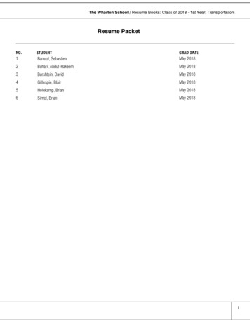
(IJACSA) International Journal of Advanced Computer Science and Applications,Vol. 9, No. 7, 2018Algorithm 1 AFL-Demand ArrivalAlgorithm 2 AFL-Demand DepartureF ; L ;z φ(u0 );for all new demand u dopcls P otcls (z);L L {u};ρmig arg maxp Vhosts {P ot0mig (z, p)};ρins arg maxp B(u,f ) {P otins (p)};p0mig P ot0mig (z, ρmig );pins P otins (ρins );if (pcls f 0) (pcls f p0mig k) thenωmig , ρmig arg maxz F,p Vhosts /{γ(z)} {P otmig (z, p)};Switch facility of each demand v C(z)/{u0 } to thepmig P otmig (ωmig , ρmig , u);closest facility in F/{z};if (pins f 0) (pins f pmig k) thenClose facility z;ωins open a facility at ρinsF F/{z};F F {ωins }else if p0mig k 0 thenSwitch facility of each demand v L/{u} ifMigrate z to point ρmig ;d(φ(v), v) d(ρins , v) h;end ifAssign u to the nearest facility;L L/{u0 }else if pmig k 0 thenAssign u to ωmig ;Migrate ωmig to point ρmig ;facility z serving u0 and the best migration potential. First,elseAFL considers the closing action. If closing z is beneficialAssign u to the nearest facility;(pcls f 0) and is more profitable than migration actionend if(pcls f p0mig k), AFL applies this action. Otherwise, theend formigration of z is considered, and if this action is profitable(p0mig k 0), AFL migrates z to ρmig . If none of closingand migration actions are beneficial, AFL only remove demandAFL applies this action. Otherwise, it assigns u to the nearest u0 from the list of demands.facility.IV. E XPERIMENTSB. Demand DepartureWe evaluated the effectiveness of our placement algorithmSimilar to the case of demand arrival, AFL defines closing in several simulation studies. We implemented our AFL algopotential and migration potential functions to represent how rithm in a discrete event simulator and compared it to other fivefar the current configuration of a facility whose demand popular algorithms namely: FFL [19], AFL [18], OPTFL [17],departures is from the stable configuration. Let u0t denotes a RFL [38], and SNFL [20]. The details of these algorithms willdemand departuring at time t, and z φ(u0t ) represents the be discussed in section V. The OPTFL, AFL, and FFL algofacility to which u0t was connected at time t 1 just before rithms have certain input parameters. We ran these algorithmsdeparture.for miscellaneous values of parameters and did not observeClosing potential function (P otcls ) is defined in equation substantial difference. Ultimately, their input parameters were8. This function denotes the profit of closing a facility and set to the values suggested by their authors, specifically forswitching its demands to the closest facilities.OPTFL α 10 [17], for AFL α 18, β 8.0, ψ 4.0 [18],and finally for FFL x 198 [19].X Inthelastdecadeatremendousresearch has been done toP otcls (z) gd(z, v) d(Ft 1 , v) h (8)searchforanefficientandinexpensivedata center networks0v Ct 1 (z)/{ut }(DCN) architecture. Several architectures like fat-trees [3],Migration potential fucntion (P ot0mig ) for the departure VL2 [24], Portland [39], BCube [25] and DCell [26] haveof a demand is defined by equation 9. It can be interpreted been proposed to address different challenges of current DCNexactly same as the migration potential for a demand arrival. architectures such as scalability, agility, and reconfigurability. For the experiment, we select Al-Fares et al. fat-treeX [3] architecture. This architecture is one of the well knownP ot0mig (z, p) gd(z, v) d(p, v)(9) DCN architectures [27] [37] [7]. Fat-trees are more scaleablev Ct 1 (z)/{u0t }and reliable than conventional tree-based architectures. ThisAFL for the departure considers two actions:topology allows us to leverage identical cheap commodity1) Closing action: Closing facility z and assigning each of switches in the all communication layers. In the theory, theits demands to the closest facility in Ft 1 /z.over-subscription ratio of this rearrangeable architecture is2) Migration action: Migration of facility z to another 1 : 1, which means that this architecture is non-blocking;location to serve Ct 1 (z)/u0t more efficiently.however, in the practice preventing packet reordering mightAlgorithm 2 represents AFL’s algorithm for handling a de- make it difficult to guaranty non-blocking network. The fatmand departure. For the sake of simplicity, we omit subscript tree topology proposed by [3] is a k-ary tree in which kt from the notation. AFL computes the closing potential of denotes number of ports and number of pods. This topologywww.ijacsa.thesai.org275 P a g e
(IJACSA) International Journal of Advanced Computer Science and Applications,Vol. 9, No. 7, 2018CoreAggregationEdgeDemands641282565121024TABLE I: AFL’s .81667.73551.96525.812798.7Note: We omit word cost from the headers. For instance, by the Facility wemean Facility CostPod 0Pod 2Pod 3Pod 4Fig. 2. The fat-tree architecture for 4 pods (k 4)connects homogeneous switches with the same number ofk ports. As depicted in Figure 2, the Al-Fares’s fat-treeconsists of three switch layers. At the highest level, thereare ( k2 )2 core-switches. Each core-switch is connected to allk pods (i-th port of a core-switch is connected to the ipod). A pod contains k switches ( k2 aggregation-switches andk2 edge-switches). At the second level, aggregation switchesare connected to k2 of core-switches upward and k2 edgeswitches downward. Furthermore, each aggregation-switch isonly connected to edge-switches that are in the same pod.At the third level, edge-switches are linked to the k2 hosts3dipping and k2 aggregation-switches mounting. There are k4hosts which are located in the leaves of this architecture. Forall experiments, the oversubscribing ratio was set to 1 : 1,which means that this architecture is non-blocking.The demands are generated randomly (only in the leaves)from the uniform and normal distributions. The mean andstandard deviation parameters of the normal distribution wereset to 0.5 and 0.1, respectively, and each generated valuewas multiplied by the number of leaves and a demand wasgenerated at the position of the result. Moreover, in all experiments, the value of parameter g was set to 1. All algorithmsreceive one demand at a time and reconfigure the placementof the facilities to serve this demand upon its arrival. Thecosts of installation, migration, and switch for all algorithmsare collected. For each configuration, the average of 10 testshas been reported as the final result. We have conductedthree experiments to evaluate the the behavior of AFL underdifferent circumstances.A. Impact of Number of DemandsIn this experiment, the impact of number of demands onthe behavior of AFL is examined. As depicted in Figure 3,five tests for 1024, 2048, 3072, 4096, and 5120 number ofdemands for uniform (Figure 3(a)) and normal distribution(Figure 3(b)) are conducted. We assign 6, 2, 1 for f , k and h,respectively. The idea behind choosing these values is that weassume that the cost of installation of a facility f is alwaysgreater than the cost of migration k and switching h, and thecost of migration is equal or greater than the cost of switching.Moreover, The space is the fat-tree with 1024 hosts. For eachtest, each algorithm receives one demand at a time and returnsa placement of facilities.As shown in Figure 3, the total cost of all algorithms inthe uniform distribution are co
Intrusion Detection and Prevention Systems are an essential defensive measure against a range of attacks [44, 47]. In enterprise networked system, IDPSs examine packets sent over networks and trigger alerts when malicious content is discovered and defend against attacks when prevention mode is active. Most issues regarding security in cloud .