Transcription
CSLP VACervical Spine Locking Platewith Variable AngleInstruments and implants approved by the AO Foundation.This publication is not intended for distribution in the USA.SURGICAL TECHNIQUE
Image intensifier controlThis description alone does not provide sufficient background for direct useof DePuy Synthes products. Instruction by a surgeon experienced in handlingthese products is highly recommended.Processing, Reprocessing, Care and MaintenanceFor general guidelines, function control and dismantling of m ulti-partinstruments, as well as processing guidelines for i mplants, please contact yourlocal sales representative or refer are-maintenanceFor general information about reprocessing, care and maintenance ofSynthes reusable devices, instrument trays and cases, as well as processing ofSynthes non-sterile implants, please consult the Important Information leaflet(SE 023827) or refer are-maintenance
Table of ContentsIndications/Contraindications 2AO Spine Principles 3Surgical Technique 4Implant Removal 13Implants 14Instruments 18Bibliography 20CSLP VA Surgical TechniqueDePuy Synthes1
Indications/ContraindicationsIndicationsThe cervical spine locking plate with variable angle is usedfor internal anterior fixations of the spine (C2–T2) forthe management of instability in the following rative disorderstumourspartial or complete resection of a vertebral bodyContraindications–– Severe osteoporosis and indications not listed above–– Any indication where fusion is not requiredNotes:–– Self-drilling expansion head screws must not be used together with cervical spine locking plates with a fixedscrew angle since this impedes correct alignment of thescrew with the plate hole, thereby preventing flush countersinking of the screw head in the plate hole. Self-drillingexpansion head screws must not be used for bicorticalscrew fixation.–– Similarly, bicortical, self-tapping expansion head screwsmust not be used together with cervical spine lockingplates with a fixed screw angle, otherwise the screw tipswould cross.–– For correct use of the cervical spine locking plates witha fixed screw angle please consult the corresponding Surgical Technique (Art. no. 036.000.062).2DePuy Synthes CSLP VASurgical Technique
AO Spine PrinciplesThe four principles to be considered as the foundation forproper spine patient management underpin the design anddelivery of the Curriculum: Stability – Alignment – Biology –Function.1,2StabilityStabilization to achievea specific therapeutic outcomesagittalaxialcoronalAlignmentBalancing the spine in threedimensionsFunctionPreservations and restoration of function to preventdisabilityBiologyEtiology, pathogenesis,neural protection,and tissue healingCopyright 2012 by AOSpine12Aebi et al (1998)Aebi et al (2007)CSLP VASurgical TechniqueDePuy Synthes3
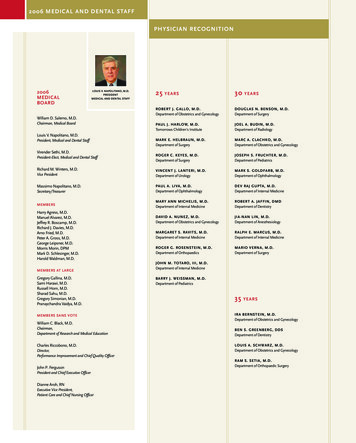
Surgical Technique1Position patient and surgical approachFor plating of the middle and lower cervical spine till T2 select the anterolateral approach. With the patient supine,turn the head slightly away from the operator. A long incision is recommended if the plating is to be extended overseveral segments.When exposing the vertebral bodies it is important to remove, or incise, the anterior longitudinal ligament only atthose points where the intervertebral disc is to be bridgedby the plating. Under no circumstances should the anteriorlongitudinal ligament be damaged in adjacent segmentsnot included in the plating.4DePuy Synthes CSLP VASurgical TechniqueC4C6
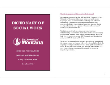
2Select, pick up and position plateSelect a plate of the approximate length. The figures markedon the plate and implant rack refer to the distance betweenthe cranial and caudal pairs of holes. Pick up the platewith the Holding Forceps for Cervical Spine Locking Plates(387.532) and position the plate on the segments to bebridged so that the pairs of holes are centred over the vertebral bodies.Precaution: Make sure there will be enough space betweenthe intact adjacent intervertebral discs and the screws.If the plate needs to be bent, ensure that the screw holes arenot distorted, otherwise it will not be possible to insert theexpansion head screws. To bend the plates, use the UniversalBending Pliers for Cervical Spine Locking Plates (387.293).Precaution: Repeated bending may weaken the plate.2b2aCSLP VA Surgical TechniqueDePuy Synthes5
Surgical Technique3Fix plateUsing the self-holding, cruciform Screwdriver Shaft4.0/4.35/4.5 (387.281) and Handle with Quick Coupling(311.430), pick up a Fixation Pin for Cervical Spine LockingPlates (387.595) and screw into a cranial plate hole. Insert asecond fixation pin into the diagonally opposite plate hole.Remove the screwdriver and holding forceps.Precaution: Intraoperative imaging should be used for alateral view of the position of the fixation pins to indicatethe potential positions of the screws.Note: Before the plate is fixed to the bone, ensure that allswivel rings are correctly inserted. The four slots in the swivelring must point upwards. If necessary, tilt and turn the swivelring in the plate hole using the tip of the cruciform screw driver shaft.3a3c6DePuy Synthes CSLP VASurgical Technique
Self-drilling screws4aPierce hole in cortexLocate the Awl for self-drilling Cervical Spine Expansion HeadScrews (387.291) on the swivel ring and align the awl according to the selected screw angle. Press the awl to pierce a holein the cortex. This hole piercing helps centre the self-drillingscrew in the plate hole and guide it in the desired direction.Precaution: Intraoperative imaging should be used to verifyawl position.4/54b4aCSLP VA Surgical TechniqueDePuy Synthes7
Surgical TechniqueSelf-tapping screws4b4Drill screw holesInsert the self-holding Drill Sleeve 3.0 (387.286) in the swivelring in the plate hole (1) and incline it in the desired direction of drilling (2). Squeeze the handle (3) and lock the drillguide by pushing the slide forward (4).32Precautions:–– Do not move the drill guide while it is inserted in theswivel ring and the handle is squeezed or locked, otherwise the interlock between the swivel ring and plate maybe weakened.–– Intraoperative imaging should be used to check the drillingoperation.1Drill Bits B 3.0 mm with StopArt. no.Depth387.22014 mm324.16016 mm387.22818 mm387.27520 mm387.23222 mm387.23424 mm387.23626 mm4/64a/68DePuy Synthes CSLP VASurgical Technique4b/6
403020Estimate the depth of the drilled hole through the platehole using the screw length indicator, depth up to 50 mm(387.292). The reading shown on the screw length indicatorscale corresponds with the screw length to be selected.50Self-tapping screws4/64d/6CSLP VA Surgical TechniqueDePuy Synthes9
Surgical TechniqueSelf-drilling/Self-tapping screws5Insert self-drilling or self-tapping expansion head screwsPick up an expansion head screw using the self-holding cruci form screwdriver shaft 4.0/4.35/4.5 and handle, insert throughthe swivel ring in the direction of the pierced/predrilled hole andtighten until the screw head is countersunk in the swivel ring.Precautions:–– Keep the screwdriver steady when picking up and insertingthe screws and only apply gentle pressure to the screws otherwise the screw head may expand prematurely, thus preventing flush countersinking.–– Intraoperative imaging should be used to verify screw position.4/54/6511DePuy Synthes CSLP VA Surgical Technique
Cervical Spine Expansion Head Screws, self-drilling,Pure Titanium*Art. no.BLengthColour code450.1374.0 mm12 mmlight blue450.1384.0 mm14 mmgold450.1394.0 mm16 mmviolet450.1444.5 mm12 mmlight blue450.1454.5 mm14 mmgold450.1464.5 mm16 mmvioletWarning: In the event of wide bridging or poor bone quality, the surgeon must decide whether the longest self drillingscrew (16 mm) will provide sufficient stability. For unstablesituations bicortical anchorage (with self tapping screws)and/or dorsal stabilization may be required. 4.5 mm self drilling screws can be used as emergency screws if a 4.0 mmscrew has damaged the bone and a larger screw thread is required.Cervical Spine Expansion Head Screw B 4.0 mm,self-tapping, Pure Titanium*Art. no.LengthColour code487.04212 mmlight blue487.04414 mmgold487.04616 mmviolet450.12718 mmlight green450.12819 mmlight green450.12920 mmlight green450.19322 mmlight green450.19524 mmlight green450.19726 mmlight green* All screws are also available sterile packed.Add suffix “S” to article number.CSLP VA Surgical TechniqueDePuy Synthes11
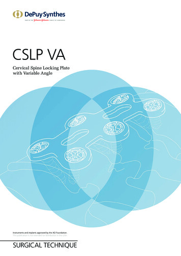
Surgical TechniqueSelf-drilling/Self-tapping screws6Lock screwsPick up Locking Screws B 1.8 mm (497.780) with the Screwdriver Shaft 1.8, cruciform, self-holding (387.285) and Handle and carefully screw into the screw heads. The lockingscrew expands the screw head and swivel ring to lock thescrew in the plate.64/5114/6DePuy Synthes CSLP VASurgical Technique
Implant RemovalRemove the locking screws B 1.8 mm from the expansionhead screws using the Screwdriver Shaft 1.8, cruciform,self-holding (387.285) and Handle with Quick Coupling(311.430). Attach the Extraction Screw, conical, with lefthand thread (387.340) to the h andle and screw counterclockwise into the expansion head screws. Remove the expansionhead screws by continuing the counterclockwise turns. Theremoved expansion head screws can be released from theconical extraction screw by clockwise turns.7CSLP VA Surgical TechniqueDePuy Synthes11
ImplantsPlatesCSLP VA Plates*One-level platesArt. No.Plate length .15633450.15735Two-level platesArt. No.Plate length .16652450.16755* All implants are also available sterile packed.Add suffix “S” to article number.11DePuy Synthes CSLP VA Surgical Technique
Three-level platesArt. No.Plate length .17669450.17772450.17875450.17978Four-level platesArt. No.Plate length 1109* All implants are also available sterile packed.Add suffix “S” to article number.CSLP VA Surgical TechniqueDePuy Synthes11
ImplantsScrews*450.127 Cervical Spine Expansion Head ScrewB 4.0 mm, self-tapping, length 18 mm,Pure Titanium, light green450.129Cervical Spine Expansion Head ScrewB 4.0 mm, self-tapping, length 20 mm,Pure Titanium, light green450.193 Cervical Spine Expansion Head ScrewB 4.0 mm, self-tapping, length 22 mm,Pure Titanium, light green450.195Cervical Spine Expansion Head ScrewB 4.0 mm, self-tapping, length 24 mm,Pure Titanium, light green450.197Cervical Spine Expansion Head ScrewB 4.0 mm, self-tapping, length 26 mm,Pure Titanium, light green487.042Cervical Spine Expansion Head ScrewB 4.0 mm, self-tapping, with cortexthread, length 12 mm, Pure Titanium,light blue487.044Cervical Spine Expansion Head ScrewB 4.0 mm, self-tapping, length 14 mm,Pure Titanium487.046Cervical Spine Expansion Head ScrewB 4.0 mm, self-tapping, length 16 mm,Pure Titanium, violet450.128Cervical Spine Expansion Head ScrewB 4.0 mm, self-tapping, length 19 mm,Pure Titanium, light green450.137Cervical Spine Expansion Head ScrewB 4.0 mm, self-drilling, length 12 mm,Pure Titanium, light blue450.138Cervical Spine Expansion Head ScrewB 4.0 mm, self-drilling, length 14 mm,Pure Titanium, gold450.139Cervical Spine Expansion Head ScrewB 4.0 mm, self-drilling, length 16 mm,Pure Titanium, violet450.144Cervical Spine Expansion Head ScrewB 4.5 mm, self-drilling, length 12 mm* All screws are also available sterile packed.Add suffix “S” to article number.11DePuy Synthes CSLP VA Surgical Technique
450.145 Cervical Spine Expansion Head ScrewB 4.5 mm, self-drilling, length 14 mm,Pure Titanium, gold450.146Cervical Spine Expansion Head ScrewB 4.5 mm, self-drilling, length 16 mm,Pure Titanium, violet497.780Locking Screw B 1.8 mm, Pure TitaniumCSLP VA Surgical TechniqueDePuy Synthes11
Instruments311.430 Handle with Quick Coupling,length 110 mm324.160Drill Bit B 3.0 mm with Stop,length 190/45 mm, drilling depth 16 mm,2-flute, for Quick Coupling387.220Drill Bit B 3.0 mm with Stop,length 180/45 mm, drilling depth 14 mm,2-flute, for Quick Coupling387.228Drill Bit B 3.0 mm with Stop, drilling depth18 mm, 2-flute, for Quick Coupling387.232Drill Bit B 3.0 mm with Stop, drilling depth22 mm, 2-flute, for Quick Coupling387.234Drill Bit B 3.0 mm with Stop, drilling depth24 mm, 2-flute, for Quick Coupling387.236Drill Bit B 3.0 mm with Stop, drilling depth26 mm, 2-flute, for Quick Coupling387.275Drill Bit B 3.0 mm, length 190/50 mm,2-flute, for Quick Coupling387.281Screwdriver Shaft 4.0/4.35/4.5, cruciform,self-holding, length 180 mm387.285Screwdriver Shaft 1.8, cruciform,self-holding, length 190 mm387.286Drill Sleeve 3.0, self-holding, for CervicalSpine Locking Plates with variable angle11DePuy Synthes CSLP VA Surgical Technique
387.291 Awl for self-drilling Cervical SpineExpansion Head Screws387.292Screw Length Indicator,Depth up to 50 mm387.293 Universal Bending Pliers for Cervical SpineLocking Plates387.340Extraction Screw, conical, with left-handthread, for Cervical Spine Locking System387.532Holding Forceps for Cervical Spine LockingPlates, angled387.595Fixation Pin for Cervical Spine LockingPlates, for temporary useCSLP VA Surgical TechniqueDePuy Synthes11
BibliographyAebi M, Thalgott JS, Webb JK (1998): AO ASIF Principles inSpine Surgery. Berlin: Springer.Aebi M, Arlet V, Webb JK (2007): AOSPINE Manual (2 vols),Stuttgart, New York: Thieme.22DePuy Synthes CSLP VASurgical Technique
10/16DSEM/SPN/0316/0464(1)All rights reserved. 036.000.362Not all products are currently available in all markets.This publication is not intended for distribution in the USA.All surgical techniques are available as PDF files atwww.depuysynthes.com/ifu0123 DePuy Synthes Spine, a division of Synthes GmbH. 2016.Synthes GmbHEimattstrasse 34436 OberdorfSwitzerlandTel: 41 61 965 61 11Fax: 41 61 965 66 00www.depuysynthes.com
Lock screws Pick up Locking Screws B 1.8 mm (497.780) with the Screw-driver Shaft 1.8, cruciform, self-holding (387.285) and Handle and carefully screw into the screw heads. The locking screw expands the screw head and swivel ring to lock the screw in the plate. 4/6 4/5File Size: 953KBPage Count: 24