Transcription
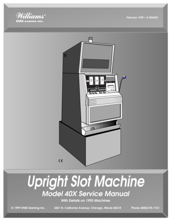
February 1999 A-004336Machine Pays Up to 400 CoinsBalance Paid by Attendant77700000 1 0 0 0 0 0All Pays on Center Line Only - Only Highest Winner PaidINSERT BILLFACE UP0,,,,Upright Slot MachineModel 40X Service ManualWith Details on 1995 Machines 1999 WMS Gaming Inc.3401 N. California Avenue, Chicago, Illinois 60618Phone (800)378-7741
February 1999A-004336Machine Pays Up to 400 CoinsBalance Paid by Attendant77700000 1 0 0 0 0 0All Pays on Center Line Only - Only Highest WinnerPaidINSERT BILLFACE UP0,,,,UprightSlotMachineModel 40XServiceManualWith Detailson 1995Machines 1999WMS Gaming Inc.
ContentsModel 40X Upright Slot MachineService Manual (A-004336)Contents .(16-004337) .1Section 1. Setup & SoftwareChapter 1. Setup.(16-004338) .1-1Procedure .1-1Lock Specifications .1-5Slot Machine Base Dimensions .1-6Gaming Device Dimensions.1-7Flammability Classification Weights.1-7Chapter 2. Diagnostic and Adjustment Software .(16-004339) .2-1Using Administration Mode .2-1Administration Mode Displays.2-2Series 0. Host Communications, Sound Volume, Demo, Cash and Credit Modes, ReelSpeed, Etc. .2-2Series 1. Input Tests .2-11Series 2. Output Tests .2-13Series 3. Hopper Test .2-15Series 4. Paytable Test .2-16Series 5. Reel Strip Test .2-17Series 6. Denomination Settings.2-18Series 7. Maximum Hopper Payout .2-20Series 8. Hopper Partial Payout Limit .2-21Series 9. Progressive ID and Level.2-21Series 10. Lamp Test .2-23Exit to Game Play Mode .2-24Chapter 3. Bookkeeping Mode.(16-004340) .3-1Using Bookkeeping Mode .3-1Bookkeeping Mode Displays.3-2Series 1. Coin Info .3-3Series 2. Play Info .3-5Series 3. Play Log .3-5Series 4. Door Info .3-6Series 5. Tilt Info .3-7Series 6. Bill Info .3-7Series 7. Bill Log .3-8Series 8. Bet Info .3-8Series 9. Cash Info .3-9Series 10. Line Info .3-9WMS Service Manual16-004337—CONTENTSS0/CH03
ContentsSeries 11. Prog Info .3-10Exit to Game Play Mode .3-10Section 2. Maintenance & TroubleshootingChapter 1. Periodic Maintenance.(16-004341) .1-1Collection and Supply .1-1Bill Validator .1-1CPU and Driver Boards, Card Cage .1-5Glass .1-7Hopper .1-9Lamps .1-12Power Distribution Unit .1-13Reels .1-13Chapter 2. Software and Game Denomination Changes . (16-004342) .2-1Software Changes .2-1Denomination Changes .2-1Card Cage Components .2-1EEPROM and RAM Interaction.2-1Software Installation.2-2Clearing the CPU Board RAM .2-3How to Perform a Soft (Partial) RAM Clearance.2-5How to Perform a Hard (Total) RAM Clearance .2-5Changing the Denomination .2-7Chapter 3. Troubleshooting.(16-004343) .3-1Tilt Codes .3-1Candle Codes .3-2Button and Switch Troubleshooting Guide.3-3Candle Codes Troubleshooting Guide .3-3Communication Troubleshooting Guide.3-3CPU Board 7-Segment Display Troubleshooting Guide .3-4CPU Board EEPROM Troubleshooting Guide .3-5CPU EPROM Troubleshooting Guide .3-5CPU Sound Jumpers .3-6CPU Startup Sounds Troubleshooting Guide .3-6Dollar Bill Validator and Coin Mechanism Troubleshooting Guide .3-7Door Troubleshooting Guide .3-8Dotmation Troubleshooting Guide.3-9Dotmation Troubleshooting Guide.3-10Hard Meter Troubleshooting Guide.3-11Hopper Troubleshooting Guide .3-12Jurisdiction Jumper Troubleshooting Guide.3-13Lamp Matrix Troubleshooting Guide .3-14Lamp Matrix.3-14PGA Chip (Programmable Gate Array) Troubleshooting Guide .3-15Power Troubleshooting Guide .3-15Progressive Troubleshooting Guide.3-16Reel LED Display Board Troubleshooting Guide .3-16Reel Opto Troubleshooting Guide .3-17Sound Troubleshooting Guide .3-184S0/CH016-004337—CONTENTSWMS Service Manual
ContentsStatic RAM Troubleshooting Guide.3-19Watchdog Timer Troubleshooting Guide .3-19Section 3. Parts ListChapter 1. Parts, Electronic .(16-004344) .1-1(In this chapter, parts appear in alphabetical order, under their assemblies.)Chapter 2. Parts, Mechanical .(16-004345) .2-1(In this chapter, parts appear in alphabetical order, under their assemblies.)Chapter 3. Large Exploded Views.(16-004346) .3-1Section 4. Vendor LiteratureSection 5. Service BulletinsSection 6. Tables & Data for CPU System 1.5 VGDs.(16-004349)Administration Mode .1Candle Codes .1I/O Board LEDs .1Startup Sound Codes .1Tilt Codes .1CPU Board 7-Segment Display.1Lamp Matrix .2Programmed and Field Programmable Chip Summary .2NOTICE Binder part number: 20-9896-02 Divider tabs part number: 16-003639 Part number for spine and cover inserts,contents section (one shrink-wrappedpackage): 16-004337 Part number for entire manual: A-004336WMS Service Manual16-004337—CONTENTSS0/CH05
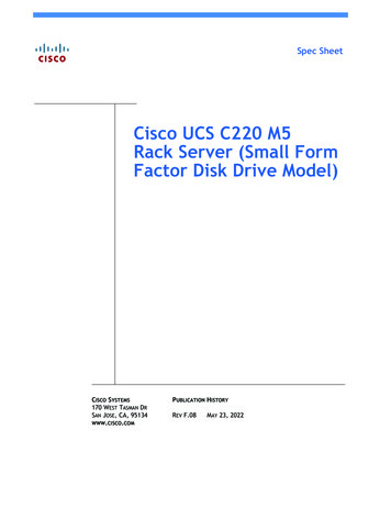
SetupBack to ContentsChapter 1. SetupPower RequirementsProcedureThis chapter explains how to inspect and install a gaming device (GD). You'llneed these tools. 11/32" NUT DRIVER PHILLIPS SCREWDRIVER ELECTRICAL OUTLET TESTERVoltage120 or 240 VACLine Freq 60 or 50 HzCurrent4 amps max. at 120 VAC2 amps max. at 240 VAC VOLTMETER 1. Remove and set aside everything from the shipping container.Inspect the cabinet exterior for damage. 2. Unlock and open the front door.Topbox LampTopboxDotmationMechanical MetersReelsChassisCard CageOn/Off SwitchFusePDU I/O BoardCPU BoardDoor SwitchHopper3. Check major components to assure that they mount securely to theslot machine. HOPPER COIN ACCEPTOR BILL VALIDATOR (BV) Bill Validator UPPER/LOWER LAMP POWER DISTRIBUTION UNIT!4. Base-Mounted Installation: Drill holes in the base to accommodatecables and the drop door connection. To assure proper holeplacement, use drilling template 31-2230-00.WMS Service Manual—Upright Slot16-004338—SETUPCAUTIONDon't install machines closer than sixinches (15.24 cm) apart.S1/CH11-1
Setup!Back to ContentsCAUTIONCAUTIONIf you install a player tracking unit (PTU)in the slot machine: The PTU should becertified by the CSA or by UL.!CAUTIONCAUTIONIf you install a player tracking unit (PTU)in the slot machine: The PTU groundwire must be connected during use, andreconnected after servicing.NOTICE 6. Base-Mounted Installation: Attach the slot machine base to the floorwith carriage bolts. Alternately, mount machines back to back on acommon base. Or, mount machines on separate bases, but bolt thebases together from back to back. 7. Operations with a Host System: Install host communication cablesaccording to recommendations of the communications systemprovider. Connect the communication cables to the backplane. 8. Attach the drop door connection to the drop door in the stand. 9. Unlock the card cage. Check for damaged or loose connectors.Don't force connectors! Close and lock the card cage.Machines That Require Special Jurisdiction Jumper Settings. 10. See the table I/O Board Jumper and DIP Switch Settings. If yourjurisdiction requires setting an I/O Board jumper, remove the I/OBoard. 11. Find the SW1 jumper bank on the I/O Board. Connect the properjumper according to the table. 12. Return the I/O Board to its slot in the card cage.All Slot Machines. 13. Check circuit boards to be sure that they mount securely to theBackplane. (The Backplane Board is behind the card cage.) 14. Close and lock the Card Cage Door. 15. Use an outlet tester to measure your line voltage at the buildingoutlet. Verify that the line voltage is nominal for your area (110 or220 volts AC).I/O Board Jumper and DIP Switch SettingsI/O JUMPERS. If you change a jumpersetting, you must perform a hard RAMclearance. See the Maintenance andTroubleshooting section.1-25. Base-Mounted Installation: Attach the slot machine to the base withsupplied bolts and nuts. Hold the carriage bolts on the slotmachine's inside cabinet floor. Tighten the nuts from inside the dropstand.CAUTIONWARNINGBASE-MOUNTED INSTALLATION:Mount machines back to back on acommon base. Or secure the base inplace. Otherwise the base can tip over,causing injury or damage.! S1/CH1DIP Bank JurisdictionStandard1New OffOffOffOffOffOffOffOffOffOffOffOffOffWMS Service Manual—Upright Slot
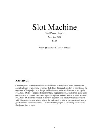
SetupBack to Contents! 16. Use an outlet tester to check for properly implemented ground, hotand neutral outlet wiring. Only use a grounded AC outlet. If the outletchecks okay, proceed. Otherwise, repair the outlet beforeproceeding. 17. Your slot machine may have a voltage range switch. You'll find thisswitch on the connector side of the PDU. Never change this switch'sposition with the line cord plugged in. Set the PDU voltage rangeswitch to match the local line voltage range. Setting this switchincorrectly, or changing the switch position under power will causedamage.CAUTIONCAUTIONTake care when setting the hopper linefrequency switch. Setting this switchincorrectly, or changing the switchposition under power will cause damage.Hopper Probe Level 18. Temporarily remove the hopper from the machine: Lift out the cointray and pull the hopper straight out. 19. The hopper has a rotary type line frequency switch. Never adjust thisswitch with the line cord plugged in. Check this switch's setting tosee that the factory setting matches the local line frequency. If not,set the switch to match the local power line frequency. You'll find theswitch on the Hopper Control Board. Access the switch by slidingout the hopper. Look at the Hopper Control Board through thewindow, beneath and beside the hopper bowl. Notice the arrow onthe switch face. This arrow points to either "110" or "220." (Theseswitch labels have nothing to do with line voltage.) In 60 Hz areas, the arrow should point to "110." In 50 Hz areas, the arrow should point to "220."To adjust the switch, insert a small screwdriver in the slot atop theswitch. Turn the screwdriver to select the hopper line frequency. 20. Plug the female end of the line cord into the slot machine's PowerDistribution Unit. You'll find the Power Distribution Unit on the lowerleft, inside cabinet wall. Drop the line cord through the base and outthe lower hole. 21. Check the slot machine for loose or missing hardware. Missinghardware may have fallen into the hopper. Clean it out of therebefore the hopper jams! Replace the hardware. 22. Check the hopper: Before filling the hopper with coins, remove dust,dirt, loose hardware and other foreign matter. 23. See the table Hopper Probe Level. Adjust the hopper coin-levelprobe. Move the probe to a higher hole if the hopper will hold morecoins. Move the probe to a lower hole if the hopper will hold fewercoins. 24. Return the hopper to the machine. Fill the hopper with coins of theproper denomination. See the table Hopper Probe Level. The tableapproximates the optimum number of coins for each coin-level probehole.WMS Service Manual—Upright Slot16-004338—SETUPProbeHole54321542U.S. 11,08071068053033025 4,0803,0302,4102,1501,7305 4,8203,6002,8502,5601,90031Probe HolesBack view of hopper, showingprobe holes.!CAUTIONCAUTIONPlugging a 120V slot machine into a240V line will damage the slot machine.!CAUTIONWARNINGInstall Electrical Outlets For GDs nearthe equipment. The outlets must beeasily accessible. Otherwise, you maynot be able to remove GD power.Working on a GD with power appliedmay expose you to hazardous linevoltage. Switching off the PDU doesn’tremove power from the interior of theGD. To eliminate this power, you mustunplug the GD.S1/CH11-3
SetupBack to Contents 25. Install a typical coin of the proper denomination in the coincomparator. If you need to adjust the coin mechanism, refer to theMaintenance and Troubleshooting section. 26. Record starting cumulative totals. (Copy them off the mechanicalmeters.) 27. Be sure that boards and connectors seat properly. Check card cageboards and connectors on door, chassis and cabinet boards. Don'tforget these connectors. BILL VALIDATOR PDU REELS BACKPLANE METERS DOOR SWITCHBOX INLINE CONNECTORSAlso check blind mating connectors: If the hopper operates, then itsconnector mates properly. If you hear the bong after power up, thenthe speaker connector mates properly. NOTICEOTHER SETUP PROCEDURES. Denomination Adjustments: See theMaintenance and Troubleshootingsection of this manual. Also seeChapter 2, Diagnostic and AdjustmentSoftware. Reel Strip Installation: Follow theprocedure in the Maintenance andTroubleshooting section of thismanual. Run the Reel Strip Testdescribed in Chapter 2, Diagnosticand Adjustment Software. Software Installation: Proceduresappear in the Maintenance andTroubleshooting section of thismanual.1-4S1/CH128. Turn on the slot machine at the Power Distribution Unit (PDU) on/offswitch. During a normal startup, these events occur. Slot machine lamps come on The reels spin and home The bill validator whines as it undergoes a self test The machine bongs once, indicating a nominal initializationIf the lamps don't light and you don't hear the bong: Did you plug theslot machine into an active, unswitched AC outlet? If you hear morethan one bong, troubleshoot the slot machine.NOTE: If any I/O DIP switch settings have been changed, a full Hard RAMClear must be performed. Refer to Section 2, Chapter 2 for the RAMClear procedure. 29. Enter Administration Mode and set the machine protocol address.(Machine Protocol Address is Series 0, Sequence 1 ofAdministration Mode.) Also set the option sound, credit mode, reels,attract mode, bills and limits. 30. Run a diagnostic check of the software and hardware. Use the slotmachine’s built-in, diagnostic software. 31. Install the locks specified by your jurisdiction. (See LockSpecification Table.) 32. Lock the front door.16-004338—SETUPWMS Service Manual—Upright Slot
SetupBack to ContentsSPECIFICATIONS FOR STANDARD LOCKS (INCHES)Dimensions, Cam Mounting Hole: Diameter 0.28" x 0.22"BarrelDouble DRotationDoorLengthHole Sizeto UnlockStacker5/8"0.76" x 0.64"CCWLogic5/8"0.76" x 0.64"CW or CCWMain5/8"0.76" x 0.64"CCWStacker Extract. Tool5/8"0.76" x 0.64"CCWBarrelDouble DRotationLock/SwitchLengthHole Sizeto UnlockNJ Extra Extract. Lk.5/8"0.76" x 0.64"CCWCam must rotate in the same direction as the lock.Opposite of Bill StackerNJ Extra Stacker Dr. Lk. 5/8"0.76" x 0.64"Door LockBarrel Lock SpacersP/N 02-4916-01: 1/16"P/N 02-4916-02: 1/8"P/N 02-4916-03: 3/16"P/N 02-4916-04: 1/4"SPECIFICATIONS FOR STANDARD LOCKS (METRIC)Dimensions, Cam Mounting Hole: Diameter .71cm x .56cmBarrelDouble DRotationDoorLengthHole Sizeto UnlockStacker1.59cm.19cm x .16cmCCWLogic1.59cm.19cm x .16cmCW or CCWMain1.59cm.19cm x .16cmCCWStacker Extract. Tool 1.59cm.19cm x .16cmCCWBarrelDouble DRotationLock/SwitchLengthHole Sizeto UnlockNJ Extra Extract. Lk. 1.59cm.19cm x .16cmCCWCam must rotate in the same direction as the lock.NJ Extra Stakr. Dr. Lk. 1.59cm.19cm x .16cmOpposite of Bill StackerDoor LockBarrel Lock SpacersP/N 02-4916-01: .16cmP/N 02-4916-02: .32cmP/N 02-4916-03: .48cmP/N 02-4916-04: .64cmWMS Service Manual—Upright Slot16-004338—SETUPS1/CH11-5
SetupBack to ContentsSlot Machine Base Dimensions1-6S1/CH116-004338—SETUPWMS Service Manual—Upright Slot
SetupBack to ContentsWide Body Slot – Model 40S Series9'' Topbox9'' Topbox w/Cardreader16'' Topbox16'' Topbox w/CardreaderBonnet TopboxBonnet Topbox w/Cardreader9.88 (25.35)12.25 (31.12)15.97 (40.56)18.34 (46.58)15.97 (40.56)18.34 (46.58)15.88 (40.34)18.25 (46.36)21.40 (54.36)23.77 (60.38)21.20 (53.85)23.57 (59.87)OverallHeightTopboxHeight30.25(76.84)19.66 (49.94)Top Flammability Classification Weights*NOTICEMeasurements are in inches and incentimeters .89241.14109.38NOTICETo allow opening of the Bill Door, spacegames at least 6” (15.24 cm) apart.*Including metal topbox, but withoutcard readerWMS Service Manual—Upright Slot16-004338—SETUPS1/CH11-7
Diag/AdjustBack to ContentsChapter 2. Diagnostic and AdjustmentSoftwareNOTICEUsing Administration ModeYour slot machine's game software includes facilities for diagnosingproblems and verifying feature operation. This software also helps you toadjust game features and performance. You can access slot machinediagnostic and adjustment functions from the Administration Mode.This chapter covers slot software up tov. 5.09.Test SeriesSlot machine software presents Administration Mode information as numericcodes on the LED displays. The software arranges the tests and setupfeatures in series. A test series number appears on the Bet Display. TheCredit and Win Meter displays convey information about each test series.See the display illustration below.Test SequenceTest or ModeCredit DisplayWin Meter DisplayBet DisplayNOTICE 1CREDITWIN METERBETAdministration Mode contains testand setup series. Most series containsequences of tests or adjustments.Some series have no sequences.Administration ModeAdministration Mode contains several series of test and setup options. (TheAdministration Mode table lists the series.) Each series contains numberedoptions. In some series, these options are tests or adjustments. In otherseries, the options are sequences of tests or adjustments.SubjectSeries0Host Communications,Sound Volume; Demo,Cash and Credit Modes,Reel Speed, Etc.1Input Tests2Output Tests3Hopper Test4Pay Table Test5Reel Strip Test6Denomination Setting7Maximum Hopper Payout8Hopper Partial Pay Limit9Progressive ID and Level10Lamp Test and CustomFeatures TestsEnter Administration Mode 1. You can enter Administration Mode while the machine operates inGame-Over Mode or Tilt Mode. (The slot machine enters GameOver Mode between games. In this mode, no bet or jackpot ispending and the hopper is inactive. Tilt Mode means that a tiltprevents game play.) Unlock and open the machine's Main Door.The words, "door oPEn" appear on the Credit and Win Meterdisplays. The Bet Display is blank. 2. Press the DIAGNOSTIC button to select a test or setup series. You'llfind this button inside the Main Door, on the front of the Card CageDoor. A zero appears on the Bet Display. This number identifies anAdministration Mode test series. Typically, data for that seriesappears in the Credit and Win Meter displays. 3. Repeatedly press DIAGNOSTIC to advance through AdministrationMode series. Continue until you find the desired test series. As inStep 2, series data usually appears on the other two displays.WMS Service Manual—Slot MachineNOTICEYou can't change Administration Modeselections from Tilt Mode. To changesettings, you must be in Game-OverMode. To enter Game-Over Mode, openand close the Main Door. Opening andclosing the Main Door also clears 22-1
Diag/AdjustBack to ContentsAdministration Mode ControlsNOTICESwitch DIAGNOSTICYou can use either the SPIN REELSbutton or the SLOT HANDLE to initiatetests. For simplicity, this chapter onlymentions the SPIN REELS button. JACKPOT RESET KEY MAX BET SLOT HANDLE SPIN REELSAdministration Mode FunctionEnters and advances through Administration Mode test series, sequencesSelects tests within a series or sequenceUsually has same effect as JACKPOTRESET KEYSame effect as SPIN REELSInitiates tests (except for input tests);selects setup optionsNOTICEYou can use either the JACKPOTRESET KEY or MAX BET to selecttests. For simplicity, this chapter onlymentions the JACKPOT RESET KEY.NOTICEIn this manual, switch or button namesappear in CAPITAL letters. For example,this manual often instructs you to “pressDIAGNOSTIC.” DIAGNOSTIC is theDIAGNOSTIC button behind the MainDoor. See the table Administration ModeControls for other common switchnames.Perform Test and Setup Functions 1. Turn the JACKPOT RESET KEY to select a test within a series orsequence. You'll find the JACKPOT RESET KEY switch near theSLOT HANDLE. Insert and turn the key. 2. Press the SPIN REELS button to initiate a test. SPIN REELS is onthe player panel. The button lights up to remind you to start the test.Exit Administration ModeTo exit Administration Mode, either. Close the Main Door (except during Door Switch Test, Series 1, Test13). Repeatedly press DIAGNOSTIC until "door open" appears on thedisplay. Displays that read this way indicate Door-Open Mode, one ofmany slot machine states. When a game reports a tilt condition, the LEDdisplays indicate the tilt type ("coinJ," "HPrE," etc).Administration Mode DisplaysThis chapter introduces an Administration Mode series or sequence with ahighlighted table. (A test series may contain several test sequences.) Eachtable presents initial values for the Credit, Win Meter and Max Bet displays.These values document the way a typical display reads before you makeadjustments. Sometimes, a series and its first sequence display identicalvalues. In that case, a table appears only at the sequence. Take a look atthe table for Series 0, Sequence 1 below.Series 0. Host Communications, Sound Volume;Demo, Cash and Credit Modes, Reel Speed, Etc.Supported Host ProtocolsCreditDisplayNONESASSdSACP2-2ProtocolNo Host CommunicationIGT SystemBally SystemWMS ProtocolS1/CH2Series 0 includes 10 sequences. Sequences 1 and 2 deal with hostcommunications protocol. Sequences 3 through 6 affect the sound system.Sequence 7 is Reel Speed. Sequences 9 and 10 enable special gamemodes.Series 0 Host Communications Protocol is the first sequence inAdministration Mode.16-004339—DIAGNOSTICS/ADJUSTMENTSWMS Service Manual—Slot Machine
Diag/AdjustBack to ContentsNOTICEChangeCash/CreditBetOneSpin ReelsMax
24. Return the hopper to the machine. Fill the hopper with coins of the proper denomination. See the table Hopper Probe Level. The table approximates the optimum number of coins for each coin-level probe hole. WMS Service Manual—Upright Slot 16-004338—SETUP S1/CH1 1-3 Setup Plugging a 120V slot machine into a 240V line will damage the slot .