Transcription
MEBS6000 Utility 0/index.htmlDesign of Cold and Hot Water SystemsDr. Sam C M HuiDepartment of Mechanical EngineeringThe University of Hong KongE-mail: cmhui@hku.hkFeb 2009
Contents Design principlesWater demandWater storagePipe sizingPipe materialsPump systemsOther considerations
Design principles Common water supply systems Cold water system We will focus on these Potable/fresh waterFlushing (salt water in HK)Cleansing waterFire serviceSwimming pool filtrationIrrigation (e.g. for landscape)Fountain circulationAir-conditioning water, etc. Hot water system (e.g. in hotels & hospitals)
Design principles Major tasks of water systems design: 1. Assessment & estimation of demands2. Supply scheme & schematic3. Water storage requirements4. Piping layout5. Pipe sizing6. Pump system design The systems must comply with WaterAuthority (WSD) requirements
Design principles General principles for installing plumbing works(from WSD Plumbing Installation Handbook) All water fittings and pipework shall comply with therelevant Waterworks Regulations All plumbing works shall be carried out in accordance withthe Hong Kong Waterworks Requirements All plumbing works shall be carried out by a licensedplumber System main pipes should preferably not be run throughthe individual premises Also, Building (Standards of Sanitary Fitments,Plumbing, Drainage Works and Latrine) Regulations
Design principles Plumbing proposal (vetted by WSD) A block plan in a scale of 1:1000 showing the location andboundary of the development The locations should be marked with datum level A plan showing the alignment and size of the proposedconnection pipes from the main to the development A plan showing the proposed alignment and size of theinternal underground water pipes to be laid in thedevelopment Vertical plumbing line diagrams
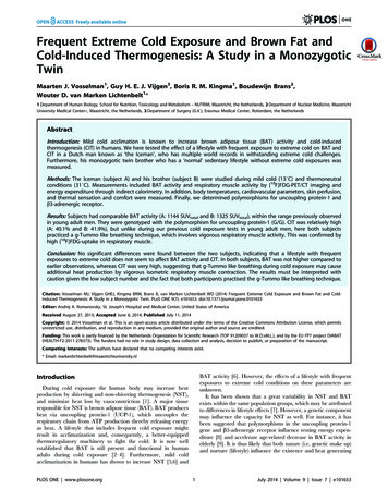
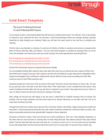
Example of aplumbingsystemschematic(fresh &flushing watersupplies)(Source: http://www.arch.hku.hk/teaching/project/f-pl.htm)
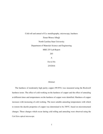
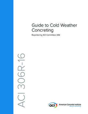
Example ofplumbinglayout design(Source: http://www.arch.hku.hk/teaching/project/f-pl.htm)
Design principles Plumbing proposal (cont’d) A schedule containing the following items : (a) number of flats/units in each block of the building (b) address of each premise needs individually metered watersupply (c) number of draw-off points and sanitary fittings in each unit (d) estimated daily consumption for all trade purposes Meters arranged in meter rooms & fittings at the meterpositions The relevant standards for the pipe materials to be used Capacities of the water storage tanks e.g. roof storage tanks
Water demand Water demand depends on: Type of building & its functionNumber of occupants, permanent or transitionalRequirement for fire protection systemsLandscape & water features Typical appliances using the cold water WC cistern, wash basin, bath, shower, sink Washing machine, dishwasher Urinal flushing cistern
Water demand Theoretical framework: Probability Theory Based on statistics & a binomial distribution n! P m (1 P ) n mPm m!(n m)! Pm probability of occurrence; n is the total number offittings having the same probability and m is number offitting in use at any one time Probability factor of a particular no. of draw off’soccurring at any one time is: P (t – time of appliance filling) / (T – time betweensuccessive usage of the appliance)
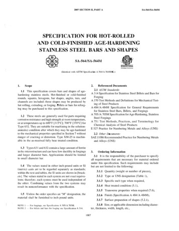
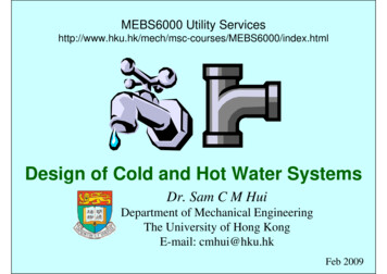
Probability graphExample:If 100appliances eachtake 30 sec tobe filled, andare used at 1200sec (20 min)frequencyinterval, then:P t/T 30/1200 0.025Using the graph,out of 100appliances, only7 would be inuse at any onetime.(Source: IOP, 2002. Plumbing Engineering Services Design Guide)
Water demand Simultaneous demand Most fittings are used only at irregular intervals It is unlikely that all the appliances will be usedsimultaneously No need to size pipework on continuous max. Key factors to consider: Capacity of appliance (litres)Draw-off flow rate (l/s)Draw-off period, or time taken to fill appliance (sec)Use frequency, time between each use (sec)
Water demand Loading Unit (L.U.) A factor given to an appliance relating the flowrate at its terminal fitting to Length of time in use Frequency of use for a particular type Use of building Evaluate the ‘probable maximum’ Relates the flow rate to the probable usage Also, consider design & minimum flow rates
Design flow rates and loading unitsDesign flow rate(l/s)Minimumflow rate (l/s)Loadingunits0.130.052WC trough cistern0.15 per WC0.102Wash basin tap size ½-DN 150.15 per tap0.101.5-3.0Spray tap or spray mixer0.05 per tap0.30---Bidet0.2 per tap0.101Bath tap, ¾-DN 200.300.2010Bath tap, 1-DN 250.600.40220.2 hot or cold0.103Sink tap, ½-DN 150.200.103Sink tap, ¾-DN 200.300.2050.2 hot or cold0.15---0.150.1030.004 per position0.002---Outlet fittingWC flushing cistern single or dual flush (tofill in 2 min.)Shower head (will vary with type of head)Washing machine size – DN 15Dishwasher size – DN 15Urinal flushing cistern(Source: Garrett, R. H., 2008. Hot and Cold Water Supply)
Water demand Apply probability theory, with caution Assume random usage with fittings (is this true?) Determine max. frequencies of use Estimate average water usage rates & time The theory is valid with large nos. of fittings Often expect to be exceeded at 1% time only Reliability and risk management (what is the consequence) Need to understand the context/circumstance Is it similar to average/typical? (* adjust data if needed) Any foreseeable special requirements?
Water demand Design flow considerations A small increase in demand over design level willcause a slight reduction in pressure/flow (unlikelyto be noticed by users) Exceptional cases, such as: Cleaners’ sinks (depends on one’s behaviour)Urinal flushing cisterns (constant small flow)Team changing rooms at sport clubs (high demand)Special events (ad hoc demand)
Water storage Purposes of water storage Provide for an interruption of supply Accommodate peak demand Provide a pressure (head) for gravity supplies Design factors Type and number of fittings Frequency and pattern of use Likelihood and frequency of breakdown of supply(often design for 12- or 24-hour reserve capacity)
Recommended minimum storage of cold and hot water systemsMinimum cold waterstorage (litres)Minimum hot waterstorage (litres)Hostel90 per bed space32 per bed spaceHotel200 per bed space45 per bed spaceOffice premises:- with canteen facilities- without canteen facilities45 per employee40 per employee4.5 per employee4.0 per employee7 per meal3.5 per mealDay school:- nursery or primary- secondary or technical15 per pupil20 per pupil4.5 per pupil5.0 per pupilBoarding school90 per pupil23 per pupilChildren’s home or residential nursery135 per bed space25 per bed spaceNurses’ home120 per bed space45 per bed spaceNursing or convalescent home135 per bed space45 per bed spaceType of buildingRestaurantNote: Minimum cold water storage shown includes that used to supply hot water outlets.(Source: Garrett, R. H., 2008. Hot and Cold Water Supply)
Estimation of cold water storage per occupantType of buildingStorage per occupant (litres)Factories (no process)10Hospitals, per bed135Hospitals, per staff on duty45Hostels90Hotels135Houses and flats135Offices with canteens45Offices without canteens35Restaurant (* per meal)7Schools, boarding90Schools, day30(Source: www.engineeringtoolbox.com)
Estimation of hot water consumptionType of buildingFactories (no process)Consumption Peak demandper occupant per occupant(litres/day)(litres/hr)22 – 459Storage peroccupant(litres)5Hospitals, general1603027Hospitals, mental1102227Hostels904530Hotels90 – 1604530Houses and flats90 – 1604530Offices2295Schools, boarding1152025Schools, day1595(Source: www.engineeringtoolbox.com)
Fixtures water requirements (demand at individual water outlets)Type of fixtureFlow rateMinimum supply(litres/min)pressure (kPa)Bathtub faucet1955Bidet7.528Laundry machine1555Lavatory faucet, ordinary7.555Lavatory faucet, self closing1055Shower head1955Shower, temperature controlled10138Sink 3/8", 1/2"1755Sink 3/4"2355Urinal flush valve56110Water closet with flush valve132170Water closet with gravity tank1055(Source: www.engineeringtoolbox.com)
Fixtures, cold water storage, hot water consumption & flow rateBasin (private)Cold waterstorage capacity(litres)90Hot waterconsumption(litre/hr)14Hot waterflow rate(litre/s)0.08Basin (public)90450.08Bath90090 – 1800.15Garden water tap180------Shower450 – 9001800.5 – 0.6Sink9045 – 900.15Urinal180------WC180------Type of fixture(Source: www.engineeringtoolbox.com)
Quantity of flushing water requiredUserAverage demandDomestic buildingsRestaurants450 litres per number ofrequired soil fitmentper day450 litres per number ofrequired soil fitmentper day13.5 litres per seat per dayCinemas4.5 litres per seat per daySchools18 litres per head per dayHotels and boarding houses90 litres per room per dayOffices, factories, department stores,shops, public buildings and othernondomestic buildings of a like nature(Source: Buildings Department HK, PNAP 17)
Water storage Minimum hot water storage capacities fordwelling (from BS6700) 35-45 litre per occupant (unless the heat sourceprovides a quick recovery rate) 100 litres for systems heated by solid fuel boilers 100 litres for systems heated by off-peakelectricity
Water storage Recovery rate and hot water storage Recovery period time to heat up the stored waterToo high a storage volume: unnecessary costsInadequate storage: loads not metNeed to consider the following factors: Pattern of useRate of heat input to the stored waterRecovery period for the hot water storage vesselAny stratification of the stored water
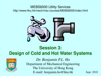
Typical heat input valuesApplianceHeat input (kW)Electric immersion heater3Gas-fired circulator3Small boiler and direct cylinder6Medium boiler and indirect cylinder10Directly gas-fired storage hot water heater (domestic type)10Large domestic boiler and indirect cylinder15(a) Bottom entry heater(b) Top entry heaterEffects of stratification(Source: Garrett, R. H., 2008. Hot and Cold Water Supply)(c) Twin entry heater
Water storage Formula to calculate recovery period M V T / (14.3 P) M time to heat the water (min.)V volume of water heated (litres)T temperature rise (oC)P rate of heat input to the water (kW) It can be applied to any pattern of use It ignores heat losses from storage vessel
Example: A small dwelling with one bath. Maximum requirement: 1bath (60 litre at 60ºC 40 litre cold water) plus 10 litre hot water at60ºC for kitchen use, followed by a second bath fill after 25 min.Thus, a draw-off of 70 litre at 60ºC is required, followed after 25 minby 100 litre at 40ºC, which may be achieved by mixing hot at 60ºCwith cold at 10ºC.Answer:1) Assume good stratification (by heating w/ a top entry heater)With 3kW heat input, the time to heat the 60 litre for the second bathfrom 10ºC to 60ºC:M V T/(14.3 P) (60 x 50)/(14.3 x 3) 70 min.The second bath is required after 25 min., thus it has to be formstorage. But in the 25 min. the volume of water heated to 60ºC is:V M (14.3)/ T (25 x 14.3 x 3)/50 21 litreTherefore, the minimum required storage capacity is:70 60 – 21 109 litre(Source: Garrett, R. H., 2008. Hot and Cold Water Supply)
Example: (Cont’d)2) Assume good mixing of the stored water (by a primary coil in anindirect cylinder)After the first bath & kitchen use, the heat energy in the 70 litrereplacement at 10ºC equals the heat energy of the water in the fullcylinder. If V is the min. size of the storage and T is the watertemperature in the cylinder after refilling:(V – 70) x 60 (70 x 10) V TT (60 V – 4200 700)/V or T 60 – 3500/VThe second bath is required after 25 min. With 3 kW heat input:25 V T / (14.3 x 3)and temperature rise T (25 x 14.3 x 3)/ V 1072.5/VA temperature of at least 40ºC is required to run the second bath.Therefore the water temperature of the refilled cylinder after the firstdraw-off, plus the temperature rise after 25 min., must be at 40ºC, or:(60 – 3500/V) (1072.5 V) 40 (or more)60 – 2427.5/V 40V 122 litre(Source: Garrett, R. H., 2008. Hot and Cold Water Supply)
Hot water storage vessel – minimum capacitiesHeat inputfor water(kW)Dwelling with 1 bathDwelling with 2 8888140200107070130130157070120130Note: * Maximum requirement of 150 litre drawn off at 60ºC (2 baths plus 10 litrefor kitchen use) followed by a further bath (100 litre at 40ºC) after 30 min.(Source: Garrett, R. H., 2008. Hot and Cold Water Supply)
Pipe sizing Correct pipe sizes will ensure adequate flow rates atappliances and avoid problems, e.g. Oversizing Additional & unnecessary installation costs Delays in obtaining hot water at outlets Increased heat losses from hot water pipes Undersizing Inadequate delivery from outlets Some variation in temperature & pressure at outlets (e.g. showersand other mixers) Some increase in noise levels For small, simple installations, pipes are often sizedbased on experience & convention
1 m head 9.81 kPa 98.1 mbarAvailable head (from cistern) vertical distance in metresfrom water line in cistern topoint under considerationAvailable head (mains supply) head at main minus heightabove main 20 m – 4 m 16 m head(Source: Garrett, R. H., 2008. Hot and Cold Water Supply)
Pipe sizing Pipe sizing procedure (a) Assume a pipe diameter (b) Determine the flow rate: 1) by using loading units 2) for continuous flow 3) obtain the design flow rate by adding 1) and 2) (c) Determine the effective pipe length: 4) work out the measured pipe length5) work out the equivalent pipe length for fittings6) work out the equivalent pipe
(Source: www.engineeringtoolbox.com) Estimation of hot water consumption Schools, boarding 115 20 25 Offices 22 9 5 Houses and flats 90 – 160 45 30 Hotels 90 – 160 45 30 Hostels 90 45 30 Hospitals, mental 110 22 27 9 30 9 Peak demand per occupant (litres/hr) Storage per occupant (litres) Consumption per occupant (litres/day) Schools, day 15 5 Hospitals, general 160 27 Factories (no process .