Transcription
Introduction toFlow Cytometry
Overview Measurement of Cellular Parameters in Flow Cytometry The Optical System of Flow Cytometers Fluidics Electronics – Digital theory Sorting – An overview2
Overview Measurement of Cellular Parameters in Flow Cytometry The Optical System of Flow Cytometers Fluidics Electronics – Digital theory3
Cellular Parameters:These particles have something in commonBlood cellsAlgaeChromosomesProtozoa Certain parameters of these particles can be measured with aflow cytometer4
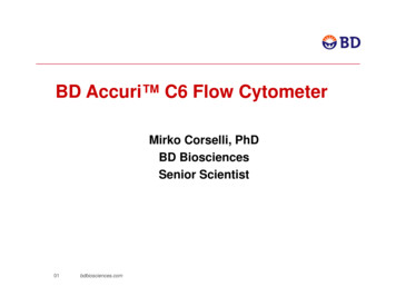
Cellular Parameters:Relative Size and ComplexityBasophilGranulocyte7 – 10 μm10 – 15 μmT cellMonocyteErythrocytes10 – 20 μmEosinophilGranulocyteNeutrophilGranulocyte Morphological, cells are different in Size Complexity5
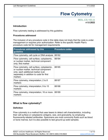
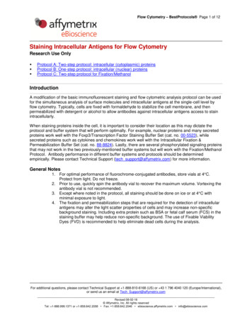
Cellular Parameters:Relative Size and ComplexityForward scatterCell size (488 nm)Coherent lightsource(488 nm)Side scatterGranularity (488 nm)Forward scatter (FSC)Side scatter (SSC) measured along the axis of the measured in 90 direction to theincoming lightexcitation light proportional the the cell size / cellsurface (only true for perfect roundcells) proportional to cell „complexity“ orgranularity6
Cellular Parameters:An example for light scattering in whole bloodSide rd scatter7
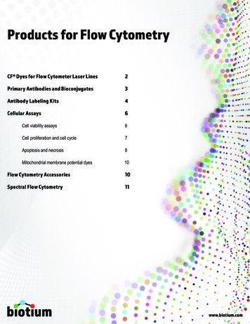
Cellular Parameters:Fluorochrome Detection and Quantificationλ 488 nmOHOλ 520 nmCCO2HIncidentLight EnergyFluoresceinMoleculeEmitted FluorescentLight EnergyAntibody The fluorochrome molecule absorbes the energy of the incoming light It releases the absorbed energy by: vibration and dissipated heat emission of a photon with a higher wavelength ( less energetic)8
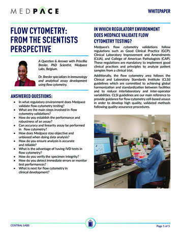
Cellular Parameters:Fluorochrome Detection and QuantificationFITCNumber of Events Fluorescence-signals measured are proportional to numbersof fluorochromes bound to cellsABFITCFITCFITCFITCTFICTCFIFITCFITCFITCFind „Min. Linearity Channel“and „Max. Linearity Channel“in the CS&T baseline report.101102103104Relative fluorescence intensity IF these are within in the “Dynamic Range” of the detector A) Minimal Linearity Channel B) Maximal Linearity Channel9
Cellular Parameters:Fluorochrome Detection and Quantification Essential for quantification:Signals that are compared with each other have to be in the dynamic range Dynamic ranges are instrument specific and dependent on Cleanness of the Flow cell Performance of the PMT etc What are detectors dynamic ranges on YOUR instrument? The CS&T baseline report can tell you!You will learn tomorrow from the “baseline report” of CS&T!10
Overview Measurement of Cellular Parameters in Flow Cytometry The Optical System of Flow Cytometers Lasers Filters and mirrors Detectors Fluidics Electronics – Digital theory11
The optical system of Flow Cytometers Overview on the optical systemOptical fibersPrismsFocuslenses1 optical fiberper laserRed Laser (635 nm)Flow Cell 670 nm564–606 nmBlue Laser (488 nm)Violet Laser (405 nm)SSC515–545 nm750–810 nm12
The optical system of Flow Cytometers Components of the optical systemLasersCreates photonsLight output is- Monochromatic and in phase- UnidirectionalFunctions13
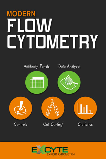
The optical system of Flow Cytometers:Lasers Excitation of fluorochromes by different lasers375nm405nm488nm561nm635nmAF 350RBD HorizonTMV450BD HorizonTMV500Pacific BlueAmCyanFITC / AF 488PerCP / 5PE-Cy 5efficiencyTMPE-Cy7PE-Cy 7approx.60%RAPC / AF 647AF 700APC-CyTM7 /BDTMAPC-H7RRExcitationefficiency 90%14
The optical system of Flow Cytometers:Lasers Excitation of fluorescent dyes by different APISYTOX BlueECFPEGFP / EYFPCFSE7-AAD / PIdsRedSYTOX GreenSYBR Green7-AAD / PImCherrymTomatomPlummOrangeDRAQ5SYTOXRed15
The optical system of Flow Cytometers Components of the optical systemLasersCreates photonsLight output is- Monochromatic and in phase- UnidirectionalFunctionsFilters / dichroid mirrorsPhoton-distribution to detectorsaccording to energy-levels(wavelengths)16
The optical system of Flow Cytometers:Filters / Mirrors Distribution of photons to detectors is filter-dependentShort-pass Filters (580nm SP)Long-pass Filters (580nm LP)Light SourceTransmitted LightLight Source 580 nm LightTransmitted Light 580 nm LightFilters in FlowCytometersNeutral-density Filters (ND1)Band-pass Filters (660/20 BP)Light SourceLight SourceTransmitted Light488 nm light (absorbs 90% of light)Transmitted Light650 – 670 nm light17
The optical system of Flow Cytometers Components of the optical systemLasersCreates photonsLight output is- Monochromatic and in phase- UnidirectionalDetectorsConvert photons into electronsPMT: e- amplificationPhotodiode: No e- amplificationFunctionsFilters / dichroid mirrorsPhoton-distribution to detectorsaccording to energy-levels(wavelengths)18
The optical system of Flow Cytometers:Detectors Photons (scattered from cells or emitted from fluorochromes) have to beconverted into electrons (electronic signal) to become analyzed Photodiodes (on conventional flow cytometers) Detected parameter: FSC Direct and proportional 1:1 conversion of photons into electrons No amplification inside the photodiode Photomultiplier Tube (PMT) Detected parameters: SSC, fluorochromes Efficiency of photon to electron conversion is wavelengths-dependent Amplification inside PMT via Dynodes19
The optical system of Flow Cytometers:Detectors Instrument Settings: Sample-dependent adaption of the PMT V to setunstained cells on scale to distinguish positive from negative samples.PMT V 500VPMT V 470Ve-e- 500V0V- 470V20
The optical systrem of Flow Cytometers:Detectors But how are the instrument settings adjusted “properly” ?As YOU like?According to 1st decade?According to grids? According to the “electronic noise” that is individual for eachinstrument! But what is the electronic noise of YOUR instrument?You will learn tomorrow from the “baseline report” of CS&T!21
Overview Measurement of Cellular Parameters in Flow Cytometry The Optical System of Flow Cytometers Fluidics Electronics – Digital theory22
Fluidics:Overview on the BD FACS Aria Fluidic SystemSheat FlowSample FlowPressurizedSheath TankSample TubeSheath FilterSample InjectionChamberFlow CellInterogation PointSample CollectionChamberWasteAspiratorCollection Tubeor Plate23
Fluidics:Hydrodynamic Focusingsheath flowsheath flowsample flowsheath flowsheath flowsample flowlaser beamslow sample pressurelaser beamshigh sample pressure24
Fluidics:Summary Sheath Pressure: Drives sheath buffer through the cuvette. Sample Pressure: Higher than Sheat Pressure. Deliverssample to Cuvette. Determines the FlowRate. Cuvette:Hydrodynamic Focussing align cells whilepassing the interception point for analysis.Important: The hydrodynamic focusing can notseparate cell agregates!25
Fluidics:Drop Formation and Charging2. Charge is applied via the stream-chargingwire.3. Charged dropletsbreak off.1a. Sample generates light scatter and fluorescentsignals; signals are analyzed.1b. Sorting decision is done according to thegating strategy and coincidences of events.4. Deflection plates attract orrepel charged droplet.5. Uncharged droplets pass towaste.6. Charged drops containingparticles of interest are collected.26
Fluidics:Drop Formation and Charging Drop Formation Amplitude:Intensity of the drop drive Frequency:Number of drops formed per second Drop1:Number of pixels from the top of the imageto the center of the first disconnected drop Gap:Number of pixels between the streambreakoff and the first drop27
Overview Measurement of Cellular Parameters in Flow Cytometry The Optical System of Flow Cytometers Fluidics Electronics – Digital theory Pulse generationData generation, storage and displayDoublete discriminationThresholds28
Electronics – Digital Theory:Pulse Generation321e-Time 3.2 μsVe-321PulseTime 3.2 μs1Time 3.2 μs2329
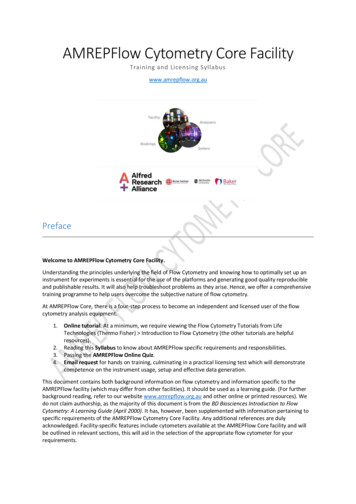
Electronics – Digital Theory:Data Generation0VEvent 239,271Pulse area (A)FITC-A5VPulse Height (H) Pulse parametersEvent 1Time (µs)89Pulse Width (W)PE-A67530,621 Data for all pulse parameters are displayed on same scalewith 262.144 channels Default parameter to display is Area (H and W have to be selected actively) Data are calculated and displayed in linear numbers30
Electronics – Digital Theory:Data Generation0VEvent 239,271Pulse area (A)FITC-A5VPulse Height (H) Pulse parametersEvent 1Time (µs)Pulse Width (W)89?PE-A67530,621 Data for all pulse parameters are displayed on same scalewith 262.144 channels Default parameter to display is Area (H and W have to be selected actively) Data are calculated and displayed in linear numbers31
Electronics – Digital Theory:Data Display In digital systems positive and negative numbers can bedisplayed in the „bi-exponential display“LogarithmicscalingBi-exponentialscaling In a system working only with linear numbers, negative valuesare as „good“ as positives – they are just smaller32
Electronics – Digital Theory:Doublet Discrimination Doublets passing the laser beam will generate one pulse!Signal IntensityFSCFSCTimeTimeSingletDoublet5 - 7 μsec3.2 μsecSignal IntensityHow can a doublet be discriminated from a single cell?33
Electronics – Digital Theory:Doublet Discrimination Doublets passing the laser beam will generate one pulse!Signal IntensityFSCFSCTimeTimeSingletDoublet5 - 7 μsec3.2 μsecSignal IntensityHow can a doublet be discriminated from a single cell?34
Electronics – Digital Theory:Threshold Area values for pulses are calculated by addition of singleHeight values for an event that exceeds above the „baseline“.Event 3Event 2Event 1145901242076501985BaselineTime35
Electronics – Digital Theory:Threshold To exclude events (e.g.: debris) you set the „Threshold“ as a2nd value that has to be exceededEvent 3Event 2Event 1145901242076501985ThresholdBaselineTime36
Electronics – Digital Theory:Threshold To exclude events (e.g.: debris) you set the „Threshold“ as a2nd value that has to be exceededEvent 3Event 2Event 114590124207650Threshold1985BaselineTime Pulses that do not exceed the thresholdare not stored. The cytometer becomes„blind“ for these events!37
Overview Measurement of Cellular Parameters in Flow Cytometry The Optical System of Flow Cytometers Fluidics Electronics – Digital theory Sorting – An overview Coincidences and Sort Decisions Drop Formation and Charging38
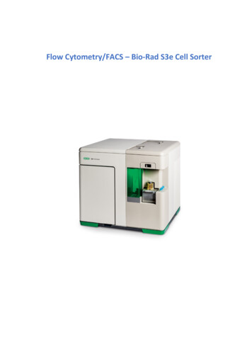
Sorting – An OverviewCoincidences and Sort Decisions Your sort decision is done according to your gating strategyBe aware: You do NOT sort cells! You sort drops!You sort a drop if one event in the drop fulfills the gating strategy!StreamWill you sortthe T cell ?Interogatedvirtual dropDebrisPlateletT cellLymphocytesT cell39
Sorting – An OverviewCoincidences and Sort Decisions Your sort decision is done according to your gating strategyBe aware: You do NOT sort cells! You sort drops!You sort a drop if one event in the drop fulfills the gating strategy!StreamYes,Will you sorteven if the platelet mighttheyourT cell? assay!screw upcytokineInterogatedvirtual dropDebrisPlateletT cellLymphocytesT cell40
Sorting – An OverviewCoincidences and Sort Decisions To reduce the chance of coincidences, we adapt the number ofevents we sort to the number of drops we produce Frequency / 4 is highest Threshold Rate (# of events / sec) Flow Rate for sorting is maximal 6Interogatedvirtual dropDebrisPlatelet90.0T cell41
Sorting – An OverviewCoincidences and Sort Decisions Also pieces of debris are „events“ that will enhance due to theirhigh numbers the sorting time significantly Enhance the threshold on FSC:events below threshold become „invisible“Interogatedvirtual dropDebrisPlateletT cell42
Sorting – An OverviewCoincidences and Sort Decisions Also pieces of debris are „events“ that will enhance due to theirhigh numbers the sorting time significantly Enhance the threshold on FSC:events below threshold become „invisible“ Optimize sample-preparation:reduce numbers of debris or plateletsInterogatedvirtual dropDebrisPlateletT cellErythrocyte-Lysing Solution2x centrifugation 300gUnfiltered PBS43
Sorting – An OverviewCoincidences and Sort Decisions Also pieces of debris are „events“ that will enhance due to theirhigh numbers the sorting time significantly Enhance the threshold on FSC:events below threshold become „invisible“ Optimize sample-preparation:reduce numbers of debris or plateletsInterogatedvirtual dropDebrisPlateletT cellErythrocyte-Lysing Solution3x centrifugation 150gFiltered PBS44
Introduction to Flow Cytometry. 2 Overview Measurement of Cellular Parameters in Flow Cytometry The Optical System of Flow Cytometers Fluidics Electronics - Digital theory Sorting - An overview. 3 Overview Measurement of Cellular Parameters in Flow Cytometry