Transcription
Xantrex GT250Grid-Tied Photovoltaic InverterXantrex GT250 480Xantrex GT250 480 PGXantrex GT250 600Operation and Maintenance Manualwww.schneider-electric.com
Xantrex GT250Grid-Tied Photovoltaic InverterOperation and Maintenance Manualwww.schneider-electric.com
Copyright and ContactTrademarksSchneider Electric, the Schneider Electric logo, and Xantrex are trademarks or registered trademarks of theSchneider Electric group of companies. Other trademarks, registered trademarks, and product names are theproperty of their respective owners and are used herein for identification purposes only.Notice of CopyrightCopyright 2008, 2009, 2010 Xantrex Technology Inc. All rights reserved. No part of this document may bereproduced in any form or disclosed to third parties without the express written consent of:Xantrex Technology Inc.161-G South Vasco RoadLivermore, California USA 94551Xantrex Technology Inc. reserves the right to revise this document and to periodically make changes to thecontent hereof without obligation or organization of such revisions or changes unless required to do so by priorarrangement.Exclusion for DocumentationUNLESS SPECIFICALLY AGREED TO IN WRITING, XANTREX TECHNOLOGY INC. (“XANTREX”)(A) MAKES NO WARRANTY AS TO THE ACCURACY, SUFFICIENCY OR SUITABILITY OF ANY TECHNICAL OR OTHER INFORMATIONPROVIDED IN ITS MANUALS OR OTHER DOCUMENTATION;(B) ASSUMES NO RESPONSIBILITY OR LIABILITY FOR LOSSES, DAMAGES, COSTS OR EXPENSES, WHETHER SPECIAL, DIRECT,INDIRECT, CONSEQUENTIAL OR INCIDENTAL, WHICH MIGHT ARISE OUT OF THE USE OF SUCH INFORMATION. THE USE OF ANYSUCH INFORMATION WILL BE ENTIRELY AT THE USER’S RISK; AND(C) REMINDS YOU THAT IF THIS MANUAL IS IN ANY LANGUAGE OTHER THAN ENGLISH, ALTHOUGH STEPS HAVE BEEN TAKEN TOMAINTAIN THE ACCURACY OF THE TRANSLATION, THE ACCURACY CANNOT BE GUARANTEED. APPROVED XANTREX CONTENT ISCONTAINED WITH THE ENGLISH LANGUAGE VERSION WHICH IS POSTED AT WWW.SCHNEIDER-ELECTRIC.COM.Date and RevisionDecember 2010 Revision DPart Number153395Contact Informationwww.schneider-electric.com North America 1 408 987 6255 1 925 245 1022re.techsupport@schneider-electric.comFrance0 825 012 schland 49 (0) 180 575 6575 49 (0) 2102 404 7101solarservice@de.schneider-electric.comEspaña 34 902 101813 34 93 305 5026es-sat@es.schneider-electric.comL'Italia 39 035 4151111 39 035415 r other country details please contact your local Schneider Electric Sales Representative or visit our website erations.page
About This ManualPurposeThe purpose of this Operation and Maintenance Manual is to provideexplanations and procedures for operating, maintaining, and troubleshooting theSchneider Electric Xantrex GT250 Grid-Tied Photovoltaic Inverter. Installationinstructions are available in the Schneider Electric Xantrex GT250 Grid-TiedPhotovoltaic Inverter Planning and Installation Manual (Part #:153396).ScopeThis Manual provides safety guidelines and information about operating andtroubleshooting the unit.AudienceChapter 1 and Chapter 2 are intended for anyone who needs to operate theXantrex GT250 Grid-Tied Photovoltaic Inverter. Operators must be familiar withall the safety regulations pertaining to operating high-voltage equipment asdictated by local code. Operators must also have a complete understanding ofthis equipment’s features and functions. Do not to use this product unless it hasbeen installed by qualified personnel in accordance with the instructions in yourXantrex GT250 Grid-Tied Photovoltaic Inverter Planning and Installation Manual.Chapter 3 and Chapter 4 are intended for qualified personnel who need toperform troubleshooting or maintenance on the Xantrex GT250 Grid-TiedPhotovoltaic Inverter. Only qualified personnel should perform thetroubleshooting and maintenance of the Xantrex GT250.Qualified personnel have training, knowledge, and experience in:153395 Revision D Installing electrical equipment and PV power systems (up to 1000 V). Applying all applicable installation codes. Analyzing and reducing the hazards involved in performing electrical work. Selecting and using Personal Protective Equipment (PPE).iii
About This ManualOrganizationThis Manual is organized into four chapters and one appendix.Chapter 1, “Introduction” provides information about the features and functionsof the Xantrex GT250 Grid-Tied Photovoltaic Inverter.Chapter 2, “Operation” contains information on the basic operation of the XantrexGT250 Grid-Tied Photovoltaic Inverter.Chapter 3, “Troubleshooting” contains information and procedures for qualifiedpersonnel to troubleshoot the Xantrex GT250 Grid-Tied Photovoltaic Inverter.Chapter 4, “Preventative Maintenance” lists the periodic maintenance thatqualified personnel need to follow to keep the Xantrex GT250 in good workingorder.Appendix A provides the environmental and electrical specifications for theXantrex GT250 Grid-Tied Photovoltaic Inverter.iv153395 Revision D
About This ManualConventions UsedThe following conventions are used in this guide.WARNINGWarnings identify conditions or practices that could result in personal injury orloss of life.CAUTIONCautions identify conditions or practices that could result in damage to the unit orother equipment.Important: These notes describe things which are important for you to know, butnot as serious as a caution or warning.Xantrex GT250 ModelsThis Operation and Maintenance Manual contains information for three models ofthe Xantrex GT250 Grid-Tied Photovoltaic Inverter.When all models are being referenced together, they will be referred to asthe Xantrex GT250.When the models are being referenced individually, they will be referred to bytheir model number, as shown in the table below.153395 Revision DModel NumberGroundingUtility Input VoltageXantrex GT250 480Negative ground480 VacXantrex GT250 480 PGPositive ground480 VacXantrex GT250 600Negative ground600 Vacv
About This ManualAbbreviations and AcronymsANSIAmerican National Standards InstituteCCU2Converter Control Unit 2CFMCubic Feet per MinuteCWClockwiseDSPDigital Signal ProcessorGUIGraphical User InterfaceIEEEInstitute of Electrical and Electronics EngineersIGBTInsulated Gate Bipolar Transistorkcmil1000 circular milsLMLiter per MinuteNFPANational Fire Protection AssociationPSLPhase-Shift LoopPVPhotovoltaicUFCUUniversal Frontpanel Control UnitVFDVacuum Fluorescent DisplayRelated InformationYou can find more information about Schneider Electric as well as its productsand services at www.schneider-electric.com.vi153395 Revision D
Important Safety InstructionsREAD AND SAVE THESE INSTRUCTIONS DO NOT DISCARDThis manual contains important safety instructions for the Xantrex GT250 GridTied Photovoltaic Inverter that must be followed during installation andmaintenance procedures.WARNING: Shock HazardRead and keep this Operation and Maintenance Manual for future reference.Before operating and maintaining the Xantrex GT250, read all instructions,cautionary markings, and all other appropriate sections of this manual. Failure toadhere to these warnings could result in severe shock or possible death.Exercise extreme caution at all times to prevent accidents.WARNING: Risk of electric shock, explosion, and arc flash The Xantrex GT250 enclosure contains exposed high voltage conductors. The enclosure doors should remain closed with the latches tightened, exceptduring installation, maintenance or testing. These instructions are for use by qualified personnel, as defined in “AboutThis Manual”, who meet all local and governmental code requirements forlicensing and training for the installation of Electrical Power Systems with ACand DC voltage to 600 volts. To reduce the risk of electric shock, do not perform any servicing other thanthat specified in the installation instructions unless you are qualified to do so. Do not open the cabinet doors if extreme moisture is present (rain or heavydew).153395 Revision Dvii
SafetyWARNING: Multiple sources with risk of electric shock,explosion, and arc flashIn order to remove all sources of voltage from the Xantrex GT250, the incomingpower must be de-energized at the source. This may be done at the main utilitycircuit breaker, the PV array disconnect, and by opening the AC disconnect andthe DC disconnect switch on the Xantrex GT250. Follow the “Lock-out and Tagout (De-energize/Isolation Procedure)” on page xi to de-energize the XantrexGT250 and test all circuits to verify that the inverter is fully de-energized, beforeservicing or maintenance. Opening the AC and DC disconnect switches on theinverter does not remove all power from the inverter. Review the systemconfiguration to determine all of the possible sources of energy. In addition, allowfive minutes for the DC bus capacitors to discharge after removing power.WARNING: Shock hazardIf a ground fault has occurred, there may be potential between TB4 and GND.The normally grounded pole may be energized and ungrounded.WARNING: Amputation hazardThe inverters contain fans with hazardous rotating parts. Keep hands away fromthe fans while the inverter is energized.WARNING: Limitations on useThe Xantrex GT250 inverters are not intended for use in connection with lifesupport systems or other medical equipment or devices. The Xantrex GT250 mayonly be used in grid-interconnected PV systems. They are not suitable for anyother application areas.viii153395 Revision D
SafetyRisksWARNING: Explosion HazardThe IGBT module may explode in the event of a major malfunction.Do not operate the inverter with the doors open.WARNING: Crush HazardThe inverters have a very high balance point and can easily topple down. Onlymove while exercising care.WARNING: Burn HazardInverters contain components that become hot during normal operation. Do nottouch.CAUTIONThe inverters have a supply air and exhaust air area, which must remainunobstructed. The device can overheat and be destroyed if the installation signsare not adhered to.CAUTIONInverter electronics can be destroyed when touched and when electrostaticallycharged. Discharge via earth potential before touching and wear appropriateprotective gear.CAUTIONNo connections or disconnections are to be made at the terminal strips orinternal connectors during operation. Turn the unit off before performing anyterminal work; wait five minutes for the capacitors to discharge and recheck toensure internal components are no longer energized.General Safety Precautions1. When installing the Xantrex GT250 use only components recommended orsold by Schneider Electric. Doing otherwise may result in a risk of fire,electric shock, injury to persons, and will void the warranty.2. Do not attempt to operate the Xantrex GT250 if it has been dropped, orreceived more than cosmetic damage during transport or shipping. If theXantrex GT250 is damaged, or suspected to be damaged, see the Warrantysection of this manual.3. To reduce the risk of electrical shock, lock out, and tag out the XantrexGT250 before attempting any maintenance, service, or cleaning.153395 Revision Dix
SafetyPersonal SafetyFollow these instructions to ensure your safety while working with the XantrexGT250.Never work alone when servicing this equipment. A team of two is required untilthe equipment is properly de-energized, locked-out and tagged-out, and verifiedde-energized with a meter.Thoroughly inspect the equipment prior to energizing. Verify that no tools orequipment have inadvertently been left behind.Qualified PersonnelOnly qualified personnel should perform the troubleshooting and maintenance ofthe Xantrex GT250. Follow all national and local electrical codes and workersafety regulations.Qualified personnel have training, knowledge, and experience in: installing electrical equipment and PV power systems (up to 1000 V), applying all applicable installation codes, analyzing and reducing the hazards involved in performing electrical work,and, selecting and using Personal Protective Equipment (PPE).Safety EquipmentAuthorized service personnel must be equipped with standard safety equipmentincluding the following: Safety glasses Ear protection Steel-toed safety boots Safety hard hats Padlocks and tags Appropriate meter to verify that the circuits are de-energized(1000 Vac and DC rated, minimum)Check local safety regulations for other requirements.x153395 Revision D
SafetyLock-out and Tag-out (De-energize/Isolation Procedure)Safety requirements mandate that this equipment not be serviced while energized.Power sources for the Xantrex GT250 must be locked-out and tagged-out prior toservicing. A padlock and tag should be installed on each energy source prior toservicing.WARNING: Risk of electric shock, explosion and arc flashReview the system schematic for the installation to verify that all available energysources are de-energized. DC bus voltage may also be present. Once allsources of input are identified and isolated, allow five minutes for all capacitorswithin the main enclosure to completely discharge before proceeding.The Xantrex GT250 can be energized from both the AC source and the DCsource. To ensure that the inverter is de-energized prior to servicing, lock outand tag out the Xantrex GT250 using the following procedure.1. Turn the Xantrex GT250 main ON/OFF switch (S3) to the OFF position. This stopsthe inverter from exporting power to the AC utility grid.2. Open, lock out, and tag out the incoming power at the utility main circuit breaker.3. Open, lock out, and tag out the AC disconnect (CB1) on the left door of theXantrex GT250. See Figure 1-10 on page 14 for the location of the ACdisconnect.4. Open, lock out, and tag out the incoming power at the PV array disconnect (ifinstalled.) If a PV array disconnect is not installed, see the WARNING below.5. Open, lock out, and tag out the DC disconnect switch (S1) on the right door ofthe Xantrex GT250 enclosure. See Figure 1-10 on page 14 for the location of theDC disconnect switch.WARNING: Risk of electric shock, explosion and arc flashSchneider Electric recommends the installation of PV array disconnect(s) to ensurepersonal safety during Xantrex GT250 maintenance. Without PV array disconnect(s),once the DC disconnect switch (S1) is open, there will still be DC voltage on the DCterminals TB3, TB4 AND TB5 (PV GND). This voltage may be as high as theopen-circuit voltage of the PV array and is limited to 600Vdc per NEC 690. Useextreme care to avoid these terminals if no PV array disconnect is installed.6. Using a confirmed, accurate meter, verify all power to the inverter isde-energized, as described in Steps 7 and 8. A confirmed, accurate metermust be verified on a known voltage before use.153395 Revision Dxi
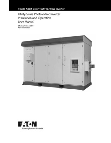
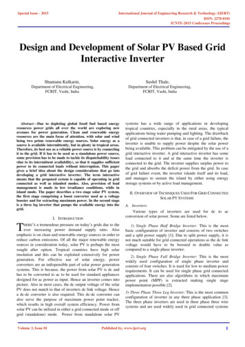
Safety7. Ensure that all incoming energy sources are de-energized by checking thefollowing AC utility terminal locations at all line-to-line and all line-to-groundconfigurations. AC Utility Terminals: [TB1-A, TB1-B, TB1-C, TB1-N, and TB2 (GND BUS)]See Figure i on page xii for the location of these terminals.TB1-N terminalTB1-B Phase terminalTB1-A Phase terminalTB2 Ground barTB1-C Phase terminalFigure i AC Terminal Connections from the Utilityxii153395 Revision D
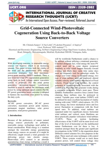
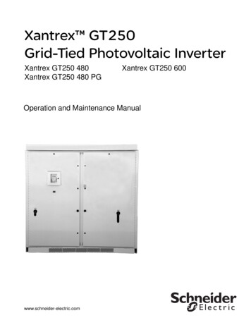
Safety8. Ensure that all incoming energy sources are de-energized by checking thefollowing PV terminal locations at PV to PV-, PV to PV ground, and PV- toPV ground configurations. PV Terminals: [TB3, TB4 and TB5 (PV GND)]See Figure ii on page xiii for the location of these terminals.WARNING: Shock hazardIf a ground fault has occurred, there may be potential between TB4 and GND.The normally grounded pole may be energized and ungrounded.Important: Note: If no external disconnect has been installed, do not checkvoltage at these points.Instead, check voltage on the inverter side of DC switch S1.TB4TB3TB5 (PV GND)Figure ii DC Terminal Locations153395 Revision Dxiii
xiv
ContentsImportant Safety Instructions - - - - - - - - - - - - - - - - - - - - - - - - - - - - - - - - - - - - - - - - - - -vii1IntroductionDescription of the Xantrex GT250 - - - - - - - - - - - - - - - - - - - - - - - - - - - - - - - - - - - - - - - - - - - - - 1–2Power Conversion System - - - - - - - - - - - - - - - - - - - - - - - - - - - - - - - - - - - - - - - - - - - - - - - - 1–2Advanced Design Features - - - - - - - - - - - - - - - - - - - - - - - - - - - - - - - - - - - - - - - - - - - - - - - 1–2Physical Characteristics - - - - - - - - - - - - - - - - - - - - - - - - - - - - - - - - - - - - - - - - - - - - - - - - - - - - 1–3AC Interface - - - - - - - - - - - - - - - - - - - - - - - - - - - - - - - - - - - - - - - - - - - - - - - - - - - - - - - - - - 1–5AC Utility Terminals - - - - - - - - - - - - - - - - - - - - - - - - - - - - - - - - - - - - - - - - - - - - - - - - - - 1–5Auxiliary Control Interface - - - - - - - - - - - - - - - - - - - - - - - - - - - - - - - - - - - - - - - - - - - - - 1–6Communications Circuit - - - - - - - - - - - - - - - - - - - - - - - - - - - - - - - - - - - - - - - - - - - - - - - 1–6Power Electronics - - - - - - - - - - - - - - - - - - - - - - - - - - - - - - - - - - - - - - - - - - - - - - - - - - - - - - 1–7Converter Control Unit (CCU2) - - - - - - - - - - - - - - - - - - - - - - - - - - - - - - - - - - - - - - - - - - 1–7Power Electronics Matrix - - - - - - - - - - - - - - - - - - - - - - - - - - - - - - - - - - - - - - - - - - - - - - 1–7DC Interface - - - - - - - - - - - - - - - - - - - - - - - - - - - - - - - - - - - - - - - - - - - - - - - - - - - - - - - - - - 1–7DC Terminals - - - - - - - - - - - - - - - - - - - - - - - - - - - - - - - - - - - - - - - - - - - - - - - - - - - - - - 1–8Heater Fans - - - - - - - - - - - - - - - - - - - - - - - - - - - - - - - - - - - - - - - - - - - - - - - - - - - - - - - - - - 1–9Circuit Diagram - - - - - - - - - - - - - - - - - - - - - - - - - - - - - - - - - - - - - - - - - - - - - - - - - - - - - - - 1–10Operator Interface Controls - - - - - - - - - - - - - - - - - - - - - - - - - - - - - - - - - - - - - - - - - - - - - - - - 1–11ON/OFF Switch - - - - - - - - - - - - - - - - - - - - - - - - - - - - - - - - - - - - - - - - - - - - - - - - - - - - - - - 1–12Auxiliary ENABLE/DISABLE - - - - - - - - - - - - - - - - - - - - - - - - - - - - - - - - - - - - - - - - - - - - - - 1–12AC Disconnect and DC Disconnect Switch - - - - - - - - - - - - - - - - - - - - - - - - - - - - - - - - - - - 1–13Operation Features - - - - - - - - - - - - - - - - - - - - - - - - - - - - - - - - - - - - - - - - - - - - - - - - - - - - - - 1–15Fixed Unity Power Factor Operation - - - - - - - - - - - - - - - - - - - - - - - - - - - - - - - - - - - - - - - - 1–15Peak Power Tracking - - - - - - - - - - - - - - - - - - - - - - - - - - - - - - - - - - - - - - - - - - - - - - - - - - - 1–15Utility Voltage/Frequency Fault Automatic Reset - - - - - - - - - - - - - - - - - - - - - - - - - - - - - - - 1–16Safety Features - - - - - - - - - - - - - - - - - - - - - - - - - - - - - - - - - - - - - - - - - - - - - - - - - - - - - - - - - 1–17Anti-Islanding Protection - - - - - - - - - - - - - - - - - - - - - - - - - - - - - - - - - - - - - - - - - - - - - - - - 1–17PV Ground Fault Detection - - - - - - - - - - - - - - - - - - - - - - - - - - - - - - - - - - - - - - - - - - - - - - - 1–17DC Over-voltage Detection - - - - - - - - - - - - - - - - - - - - - - - - - - - - - - - - - - - - - - - - - - - - - - 1–17Communication Features and Methods - - - - - - - - - - - - - - - - - - - - - - - - - - - - - - - - - - - - - - - - 1–18System Status and Fault Reporting - - - - - - - - - - - - - - - - - - - - - - - - - - - - - - - - - - - - - - - - - 1–18Data Logging - - - - - - - - - - - - - - - - - - - - - - - - - - - - - - - - - - - - - - - - - - - - - - - - - - - - - - - - 1–20Oscillography - - - - - - - - - - - - - - - - - - - - - - - - - - - - - - - - - - - - - - - - - - - - - - - - - - - - - - - - 1–21Optional Equipment - - - - - - - - - - - - - - - - - - - - - - - - - - - - - - - - - - - - - - - - - - - - - - - - - - - - - - 1–21Communication Modems - - - - - - - - - - - - - - - - - - - - - - - - - - - - - - - - - - - - - - - - - - - - - - - - 1–212OperationDescription of System Operation - - - - - - - - - - - - - - - - - - - - - - - - - - - - - - - - - - - - - - - - - - - - - - 2–2Overview - - - - - - - - - - - - - - - - - - - - - - - - - - - - - - - - - - - - - - - - - - - - - - - - - - - - - - - - - - - - 2–2153395 Revision Dxv
ContentsFaults - - - - - - - - - - - - - - - - - - - - - - - - - - - - - - - - - - - - - - - - - - - - - - - - - - - - - - - - - - - - - - - 2–2Alerts - - - - - - - - - - - - - - - - - - - - - - - - - - - - - - - - - - - - - - - - - - - - - - - - - - - - - - - - - - - - - - - 2–2Operating States - - - - - - - - - - - - - - - - - - - - - - - - - - - - - - - - - - - - - - - - - - - - - - - - - - - - - - - - - 2–3Shutdown - - - - - - - - - - - - - - - - - - - - - - - - - - - - - - - - - - - - - - - - - - - - - - - - - - - - - - - - - - - - 2–4Transition - - - - - - - - - - - - - - - - - - - - - - - - - - - - - - - - - - - - - - - - - - - - - - - - - - - - - - - - - - - - 2–4Power Tracking - - - - - - - - - - - - - - - - - - - - - - - - - - - - - - - - - - - - - - - - - - - - - - - - - - - - - - - - 2–4Automatic Sleep Test - - - - - - - - - - - - - - - - - - - - - - - - - - - - - - - - - - - - - - - - - - - - - - - - - - - 2–4Manual Current - - - - - - - - - - - - - - - - - - - - - - - - - - - - - - - - - - - - - - - - - - - - - - - - - - - - - - - - 2–4Fault - - - - - - - - - - - - - - - - - - - - - - - - - - - - - - - - - - - - - - - - - - - - - - - - - - - - - - - - - - - - - - - 2–4Operator Interface - - - - - - - - - - - - - - - - - - - - - - - - - - - - - - - - - - - - - - - - - - - - - - - - - - - - - - - - 2–6UFCU Keypad Operation and VFD Display - - - - - - - - - - - - - - - - - - - - - - - - - - - - - - - - - - - - 2–6VFD Display - Initialization Screen - - - - - - - - - - - - - - - - - - - - - - - - - - - - - - - - - - - - - - - - - - 2–7Standard Display - - - - - - - - - - - - - - - - - - - - - - - - - - - - - - - - - - - - - - - - - - - - - - - - - - - - - - 2–8Menu Structure - - - - - - - - - - - - - - - - - - - - - - - - - - - - - - - - - - - - - - - - - - - - - - - - - - - - - - - - 2–8READ Menu - - - - - - - - - - - - - - - - - - - - - - - - - - - - - - - - - - - - - - - - - - - - - - - - - - - - - - - 2–9WRITE Menu - - - - - - - - - - - - - - - - - - - - - - - - - - - - - - - - - - - - - - - - - - - - - - - - - - - - - - 2–16Commanding Goal State Changes - - - - - - - - - - - - - - - - - - - - - - - - - - - - - - - - - - - - - - - - - 2–23Setting the Date and Time - - - - - - - - - - - - - - - - - - - - - - - - - - - - - - - - - - - - - - - - - - - - - - - 2–24Manual State Transitions - - - - - - - - - - - - - - - - - - - - - - - - - - - - - - - - - - - - - - - - - - - - - - - - 2–25Automatic State Transitions - - - - - - - - - - - - - - - - - - - - - - - - - - - - - - - - - - - - - - - - - - - - - - 2–25Auto-restart Feature - - - - - - - - - - - - - - - - - - - - - - - - - - - - - - - - - - - - - - - - - - - - - - - - - - - - - - 2–26Energize Procedure (Startup) - - - - - - - - - - - - - - - - - - - - - - - - - - - - - - - - - - - - - - - - - - - - - - - 2–27Computer Communications with the Xantrex GT250 - - - - - - - - - - - - - - - - - - - - - - - - - - - - - - - 2–273TroubleshootingFaults and Fault Codes - - - - - - - - - - - - - - - - - - - - - - - - - - - - - - - - - - - - - - - - - - - - - - - - - - - - 3–2Alerts - - - - - - - - - - - - - - - - - - - - - - - - - - - - - - - - - - - - - - - - - - - - - - - - - - - - - - - - - - - - - - - 3–2General Troubleshooting - - - - - - - - - - - - - - - - - - - - - - - - - - - - - - - - - - - - - - - - - - - - - - - - - - - 3–2Clearing Faults Manually - - - - - - - - - - - - - - - - - - - - - - - - - - - - - - - - - - - - - - - - - - - - - - - - - - - 3–3Fault Code Descriptions - - - - - - - - - - - - - - - - - - - - - - - - - - - - - - - - - - - - - - - - - - - - - - - - - - - - 3–5Alert Code Descriptions - - - - - - - - - - - - - - - - - - - - - - - - - - - - - - - - - - - - - - - - - - - - - - - - - - - 3–164Preventative MaintenanceMaintenance Safety - - - - - - - - - - - - - - - - - - - - - - - - - - - - - - - - - - - - - - - - - - - - - - - - - - - - - - Periodic Maintenance - - - - - - - - - - - - - - - - - - - - - - - - - - - - - - - - - - - - - - - - - - - - - - - - - - Monthly Intervals or As Required - - - - - - - - - - - - - - - - - - - - - - - - - - - - - - - - - - - - - - - Six Month Intervals - - - - - - - - - - - - - - - - - - - - - - - - - - - - - - - - - - - - - - - - - - - - - - - - - -4–24–24–24–3A SpecificationsSystem Specifications - - - - - - - - - - - - - - - - - - - - - - - - - - - - - - - - - - - - - - - - - - - - - - - - - - - - - A–2Environmental Specifications - - - - - - - - - - - - - - - - - - - - - - - - - - - - - - - - - - - - - - - - - - - - - - A–2Electrical Specifications - - - - - - - - - - - - - - - - - - - - - - - - - - - - - - - - - - - - - - - - - - - - - - - - - - A–3Regulatory Specifications - - - - - - - - - - - - - - - - - - - - - - - - - - - - - - - - - - - - - - - - - - - - - - - - A–3Over Voltage, Under Voltage and Frequency Ranges - - - - - - - - - - - - - - - - - - - - - - - - - - - - A–4Arc Flash Information - - - - - - - - - - - - - - - - - - - - - - - - - - - - - - - - - - - - - - - - - - - - - - - - - - - A–5153395 Revision Dxvi
ContentsBolt Sizing and Torque Requirements - - - - - - - - - - - - - - - - - - - - - - - - - - - - - - - - - - - - - - - - A–6Dimensions - - - - - - - - - - - - - - - - - - - - - - - - - - - - - - - - - - - - - - - - - - - - - - - - - - - - - - - - - - - - - A–7Warranty and Return Information - - - - - - - - - - - - - - - - - - - - - - - - - - - - - - - - - - - - - - - - WA–1Index - - - - - - - - - - - - - - - - - - - - - - - - - - - - - - - - - - - - - - - - - - - - - - - - - - - - - - - - - - - - - - - - - - - -IX–1153395 Revision Dxvii
xviii
FiguresFigure 1-1Figure 1-2Figure 1-3Figure 1-4Figure 1-5Figure 1-6Figure 1-7Figure 1-8Figure 1-9Figure 1-10Figure 1-11Figure 1-12Figure 2-1Figure 2-2Figure 2-3Figure 2-4Figure 2-5Figure 2-6Figure 2-7Figure 2-8Figure 2-9Figure 3-1Figure A-1Main Inverter (Open Enclosure View) - - - - - - - - - - - - - - - - - - - - - - - - - - - - - - - - - - - - 1–3Xantrex GT250 Major Sections - - - - - - - - - - - - - - - - - - - - - - - - - - - - - - - - - - - - - - - - - 1–4AC Utility Terminals - - - - - - - - - - - - - - - - - - - - - - - - - - - - - - - - - - - - - - - - - - - - - - - - - 1–5Auxiliary Control Terminals - - - - - - - - - - - - - - - - - - - - - - - - - - - - - - - - - - - - - - - - - - - - 1–6DC Terminals - - - - - - - - - - - - - - - - - - - - - - - - - - - - - - - - - - - - - - - - - - - - - - - - - - - - - 1–8Heater Fan Locations - - - - - - - - - - - - - - - - - - - - - - - - - - - - - - - - - - - - - - - - - - - - - - - - 1–9Xantrex GT250 Circuit Diagram- - - - - - - - - - - - - - - - - - - - - - - - - - - - - - - - - - - - - - - - 1–10Xantrex GT250 Operator Interface Components - - - - - - - - - - - - - - - - - - - - - - - - - - - - 1–11ON/OFF Switch - - - - - - - - - - - - - - - - - - - - - - - - - - - - - - - - - - - - - - - - - - - - - - - - - - - 1–12AC and DC Disconnect Switches - - - - - - - - - - - - - - - - - - - - - - - - - - - - - - - - - - - - - - 1–14Maximum Peak Power Tracking - - - - - - - - - - - - - - - - - - - - - - - - - - - - - - - - - - - - - - - 1–16VFD Display and UFCU Location - - - - - - - - - - - - - - - - - - - - - - - - - - - - - - - - - - - - - - 1–19State Transition Diagram - - - - - - - - - - - - - - - - - - - - - - - - - - - - - - - - - - - - - - - - - - - - - 2–3Operating States Flow Chart for Power Tracking - - - - - - - - - - - - - - - - - - - - - - - - - - - - 2–5The Universal Front Panel Control Unit (UFCU) and VFD - - - - - - - - - - - - - - - - - - - - - - - 2–6Initialization Screens - - - - - - - - - - - - - - - - - - - - - - - - - - - - - - - - - - - - - - - - - - - - - - - - 2–7Operator Interface Menu Diagram- - - - - - - - - - - - - - - - - - - - - - - - - - - - - - - - - - - - - - - 2–9Scrolling through the READ Menu - - - - - - - - - - - - - - - - - - - - - - - - - - - - - - - - - - - - - - 2–11Read-by-ID Feature - - - - - - - - - - - - - - - - - - - - - - - - - - - - - - - - - - - - - - - - - - - - - - - - 2–15State Transition Diagram - - - - - - - - - - - - - - - - - - - - - - - - - - - - - - - - - - - - - - - - - - - - 2–23VFD showing Fault Code - - - - - - - - - - - - - - - - - - - - - - - - - - - - - - - - - - - - - - - - - - - - 2–26VFD showing Fault Code - - - - - - - - - - - - - - - - - - - - - - - - - - - - - - - - - - - - - - - - - - - - - 3–4Xantrex GT250 Dimensions - - - - - - - - - - - - - - - - - - - - - - - - - - - - - - - - - - - - - - - - - - A–7153395 Revision Dxix
xx
TablesTable 1-1Table 2-1Table 2-2Table 2-3Table 3-1Table 3-2Table A-1Table A-2Table A-3Table A-4Table A-5Table A-6Table A-7Table A-8DC Terminal Polarity - - - - - - - - - - - - - - - - - - - - - - - - - - - - - - - - - - - - - - - - - - - - - - - - 1–8Scrolling through the Read Menu Parameters - - - - - - - - - - - - - - - - - - - - - - - - - - - - - 2–10READ Menu Descriptions - - - - - - - - - - - - - - - - - - - - - - - - - - - - - - - - - - - - - - - - - - - - 2–12Write Menu Parameters - - - - - - - - - - - - - - - - - - - - - - - - - - - - - - - - - - - - - - - - - - - - - 2–17Fault Codes- - - - - - - - - - - - - - - - - - - - - - - - - - - - - - - - - - - - - - - - - - - - - - - - - - - - - - - 3–5Alert Codes - - - - - - - - - - - - - - - - - - - - - - - - - - - - - - - - - - - - - - - - - - - - - - - - - - - - - - 3–16Environmental Specifications - - - - - - - - - - - - - - - - - - - - - - - - - - - - - - - - -
Photovoltaic Inverter Planning and Installation Manual (Part #:153396). Scope This Manual provides safety guidelines and information about operating and troubleshooting the unit. Audience Chapter 1 and Chapter 2 are intended for anyone who needs to operate the Xantrex GT250 Grid-Tied Photovoltaic Inverter. Operators must be familiar with