Transcription
The Office of Oil and Gas; Oil and Gas WellsWest Virginia Department of Environmental ProtectionChapter §22 Article 1, Article 6 and Article 6A Office of Oil and GasChapter §22C Article 9 Oil and Gas ConservationWELL SITE SAFETY PLANSand Collision Avoidance Protocol Deep Well Policy Statement Natural Gas Horizontal WellControl Act §22-6AWest VirginiaOct 7th, 2015
Site Safety Plans Prevention measures Protection procedures Action protocols necessary
Well Site Safety Plans Authority requirements by: Deep Well Policy Statement Natural Gas Horizontal Well Control Act§22-6A
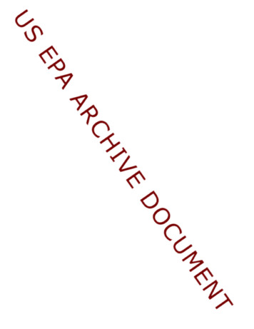
Deep Well Policy Statement by the Office of Oil and Gas Oil and Gas Conservation CommissionAgreement Policy REVISED - October 22nd, 2012 [doc1Requires Site Safety Plans ALL - DEEP PERMITTED WELLS Site specific Safety Plan must be submittedwith each deep well application . . .which cover and include Deep Well Drilling Procedures andthe Site Safety Plan Requirements]
§22-6A Well Site Safety PlansSubmit with each well permit application Applies to any natural gas well drilled using ahorizontal drilling method provided . . . Well site disturbance of three acres or moreof surface Utilizes more than two hundred ten thousandgallons of water in any thirty day period Address measures to be employed by the operator Protection of persons on the site, as well as thegeneral public and the environment.
§22-6A Well Site Safety PlansSite Safety Plans are promulgated by . . .§35-8- Rules Governing Horizontal WellDevelopment (Legislative Rule)sec. 1.1. Scope. -- This rule shall govern and apply toproceedings under W. Va. Code §22-6A-1, et seq.,related to horizontal wells. Certain portions of thisrule also govern and apply to W. Va. Code § 22-12-1,et seq., related to groundwater protection.1.2. Authority. -- W. Va. Code §§ 22-1-3 and 22-6A-6(a)(4).1.3. Filing Date. -- April 21, 20141.4. Effective Date. -- June 1, 2014
§35-8-5.7 Well Site Safety PlanEmphasis and Scope necessities . . . Encompass all aspects of the operations actual well work duringdrilling, completion ,and production activities Provide emergency point of contact Provide copy to the *LEPC at least 7 daysprior to well work or site construction*WV HSEM Information1(304)558-5380
Well Site Safety Plan StandardsGeneral Summary of Criteria Needs– Siting: site descriptions, topographic view–––––––––––LEPC emergency planning and ER familiarizationsSafety meetings, contacts, evacuationsMSDS availability and whereWell bore program, casing/cementingStrata incl. abnormal expectationsWell control & BOP equipmentTesting measures and schedules, trainingWell flaring operations & kill proceduresH2S operations and handlingWellbore collision avoidance protocolsNotification method and protection zones
Preamble to Site Safety Plans§35-8-5.7.a. Rules Governing Horizontal Development– All well applications shall be accompanied by a well site safety plan (SSP)– SSP shall address proper safety measures employed to protect: The Persons on the well site, and The General Public in the area surrounding the well site– Each SSP shall be specific to the well site and the surrounding area as describedin the well permit application– SSP shall encompass all aspects of the operation including: Actual well work for which the permit is sought Anticipated MSDS Sheets, and Drilling, completion, production, and work-over activities– SSP shall be made available on the well site during all phases of the operation– SSP provides an emergency point of contact and twenty-four (24) hour contactinformation for the well operator– SSP copy shall be provided to the County LEPC at least seven (7) days prior towell work or site/land disturbance– SSP shall be provided to the surface owner and any water purveyor or surfaceowner subject to notice and water testing as provided in section 15 of this rule– The Operator should work closely with the local responders to familiarizethem with potential incidents that are related to oil and gas development, sothat the local first responders have the information they need to provide thesupport necessary for the operator to implement the well site safety plan.
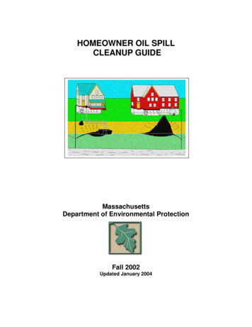
Site Safety Plan - OUTLINEDescriptive Availability On-line [ doc2 ] Site Safety Plan Table of Contents . . .1.2.3.4.5.6.7.8.9.10.Contacts, Schedules, ER coordination, and MeetingsMaps and DiagramsWell Work DescriptionsChemical Inventory & MSDSBOP and Well ControlHydrogen Sulfide (H2S)FlaringCollision Avoidance Safeguards, Practices and StandardsDeep Well Additional Requirements (Deep Well Distinction)Deep Vertical Well Requirements per Policy Statement**selections are needed from the above contents
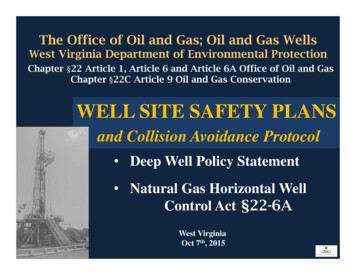
Collision Avoidance ProtocolPlans and Outline*Descriptive Availability On-line [ doc3 ]Established minimums are in pursuance to:§35-8-5.7.c.7. Rules Horizontal DevelopmentA protocol and established safeguardsdesigned to prevent underground collisionsduring any drilling on multi-well pads.* Table of Contents . . .Introduction – Purpose and ScopeA. Established definitionsB. Established descriptions of riskC. Plan components
Preamble to Collision AvoidanceSafeguards, Practices and Standards PlanIntroduction and Recognition - Purpose and Scope Measures keeping wellbores separated and HSE restrained Recognizes survey accuracy and the survey maintenance Shall be well specific to the proposed wellbore Shall address all items within the contents outlined Shall provide survey designs throughout the proposedwellbore including the QC / QA activities and the counteractions necessary Minimum separation factors and standards apply Shall include proposed counter-actions necessary if acollision occurs or if surveys observe an imminent risk for acollision All wellbore collisions shall be treated as high-risk events Approved plans are conditions and terms of the well permitand any modifications are subject to approval
Collision Avoidance Safeguards,Practices and Standards PlansA. Established definitions: Proposed Wellbore - vertical top-hole, the curve, and the lateral.Nudging – intentional well path diverted (generally in vertical section)KOP - kick off Point. Diverting a well path one trajectory to anotherMWD – Measurement While Drilling.LWD – Logging While Drilling.SF – Separation Factor or Clearance Factor:SF* CC [ URref URoff ] Collision Avoidance Calculation*R Type Rule Common Practice – Recognized by ISCWSAThe Industry Steering Committee on Wellbore Survey Accuracy CC - well separation distance (center to center of wellbores) URref - radius ellipse of uncertainty on reference well URoff - radius ellipse of uncertainty on offset well Calculation options may be considered TMD – Total Measured Depth. Gyro – High accuracy well bore survey instrument unaffected bymagnetic interference. QC / QA – Quality Control and Quality Assurance. HSE – Health Safety and the Environment.
Collision Avoidance Safeguards,Practices and Standards PlansB. Established collision risks: SF 1.0Level 1 SF 1.0 to 1.5 Level 2 SF 1.5 to 2.0 Level 3 SF 2.0Level 4Extreme riskHigh riskModerate riskLow to no risk
Collision Avoidance Safeguards,Practices and Standards PlansC. Plan components:1) Describe the scope of work and the type of surveytechniques by use of gyros, MWD, LWD, or others andinclude the following:a) The survey intervals or frequencies proposed asadjustments to address each level of risk covering thevertical top-hole section of the proposed wellbore.b) Provide TOOL ALIGNMENT and MULESHOE procedures**when drilling in critical areas covering the vertical tophole section of the proposed wellbore. Theseprocedures are visual verification for alignment andorientation QC/QA purposes. Provide the responsiblepersonnel (minimum two representatives) and theirtitles of those involved for QC/QA purposes during thedrilling activities. **Provide other orientations or surveymethods and procedures if utilized.
Collision Avoidance Safeguards,Practices and Standards PlansC. Plan components: (cont.)1)(Cont.) Describe the scope of work and the type of surveytechniques by use of gyros, MWD, LWD, or others andinclude the following:c) Description of any nudge activity proposed in the vertical tophole section.d) The survey tools to be utilized from the KOP to the laterallanding and the lateral section to the TMD.e) Description of any software utilized for the directional andanti-collision planning proposed. (Rule Type Policy utilized)
Collision Avoidance Safeguards,Practices and Standards PlansC. Plan components: (cont.)2) The following shall be addressed in the plan for theproposed wellbore:a) Vertical top-hole section beginning at the surface and to thelateral landing –i. Minimum SF standards (thresholds) required - SF 1.5shall be obtained early as practical and maintained.(Indicate the frequency of survey intervals proposed)ii. Minimum SF standards (thresholds) required - SF 2.0***applies when in proximity to any fractured or anyproducing well that exists on the well pad. (Indicate thefrequency of survey intervals proposed) ***Riskmanagement and technological mitigations, i.e. downholeplugs, are critical and should be considered along withother safety measures necessary. The OOG may requireadditional safety measures of a specific well applicationfor permitting as deemed necessary.
Collision Avoidance Safeguards,Practices and Standards PlansC. Plan components: (cont.)2) (Cont.) The following shall be addressed in the plan for theproposed wellbore:b) Lateral section beginning at the lateral landing andto the TMD i. Provide a general protocol to declination, grid correction,and magnetic interference correction during the drillingof the proposed lateral. Also provide the responsiblepersonnel (minimum two representatives) and their titlesof those involved for QC/QA purposes during the drillingactivities.ii. For any existing horizontal or vertical wells foundadjacent to this lateral section, provide the protocols forseparation safeguards and the spacing planned during thedrilling of this section. A reconnaissance review isrequired for each proposed lateral; OOG may establish aminimum footage for review as deemed necessary.
Collision Avoidance Safeguards,Practices and Standards PlansC. Plan components: (cont.)3) Provide a well pad surface diagram depicting the wellheadarrangement (API labeled) of all existing wells adjacent to theproposed wellbore. Indicate the surface footage separationbetween wellheads and each wellbore status.4) Describe the gyro surveying or other type surveying conductedwithin each existing wellbore located on the pad.5) Provide descriptive actions if a collision should occur or if surveysshould observe imminent risk for a collision.6) Provide method to notify the OOG Oil and Gas Inspectorimmediately of any underground collision or if the SF Level 1 isdetermined within the extreme collision risk zone (ellipses ofuncertainty overlap).7) Provide other supportive resources or proposed safety measuresas needed.
Flaring OperationsPlease contact theDivision of Air Quality* WVDAQWVDEP*New Source Review PermittingPhone: 304 926 0475 Fax: 304 926 0479
In Conclusion Recently incidents are reduced and isolated,and nothing is reported with downhole collisions. Continue Planning and Implementations Site Safety Plans – Complete and Indexed ContentMaintain Trainings and CertificationsContinue Safety Meetings and Practice DrillsCommunications, Contacts and NotificationsPersonnel - Public ProtectionsEnvironmental Protections - Waste Conservation. Continue QC/QA efforts Designs / Activities Wellbore and Well ControlsSurface Managements and Controls. Explore Areas: Training/Certification/Conservation.
David J. BelcherOffice of Oil and GasDepartment of Environmental Protection601 57th Street, SECharleston, WV gov
doc1
Revised (3/15)doc2Site Safety Plan Table of ContentsFor H6A Well Work Permits and Deep Well Work PermitsPlease prepare a Site Safety Plan to accompany each applicable H6A and/or Deep well work permit, adheringto the following organizational and informational structure. Plans submitted must contain an index of thecontent entirety including page-number references.1. Contacts, Schedules, and MeetingsA. Emergency point of contact for the well operator covering all phases of activities and including 24 hourcontact information (35-8 5.7.b.4)B. List of telephone numbers for (35-8 5.6.4):1) Operator2) Contractors3) DEP office and oil/gas inspector4) Local emergency response units5) Local ER personnel6) All schools and public facilities within a one mile radius of proposed well site (35-8 5.7.b.5)C. Method of notification of public of H2S gas presence and how access will be controlled. (applicablehorizontal wells include all residents and emergency response personnel who may be affected by anevent. Such events may include the presence of H2S, blow-outs, and flaring) (35-8 5.7.f.1)D. Pre-spud meeting held prior to drilling operations, including (35-8 5.7.h):1) Attendance log, including personnel to be employed and involved in drilling operations2) Notification of County oil and gas inspector or other designated Office of Oil and GasrepresentativeE. Describe schedule for conducting regular well site safety meetings. Log attendance at all meetings andalso initiate check in check out during drilling, completion, and workover phases. (35-8 5.7.h)2. Maps and DiagramsA. Plan view map of location, access road, pit(s), flare lines, nearby dwellings, note the north directionand the prevailing wind direction (35-8 5.7.b.1)B. Topographic map of well location, including1) 1 mile radius of well location2) UTM NAD 83 coordinates of well site entrance (35-8 5.7.b.2)3) UTM NAD 83 coordinates of the point the access road intersects the public route (35-8 5.7.b.2)4) Identify public route number and/or route name (35-8 5.7.b.2)C. Evacuation plan for the removal of personnel from the drilling location and residents in thesurrounding area who have the potential to be affected by an emergency. (35-8 5.7.b.3)3. Well WorkA. Detailed written descriptions of well work and procedure to be used during the drilling, completion,and production phases, including schematic plan views of each (35-8 5.7.a)B. Statement detailing how a copy of the plan will be provided to the local emergency planningcommittee or county emergency services office within at least 7 days from land disturbance or wellwork. (35-8 5.7.a)Page 1 of 5
Revised (3/15)4. Chemical Inventory & MSDSA. Material Safety Data Sheets for all chemicals anticipated to be used in all aspects of the operation (canbe provided on CD or USB drive) (35-8 5.7.a)B. Statement that all MSDS are to be readily available at the well site and their location indicated in thesite safety plan including contact information for person(s) responsible maintaining them on site. (35-85.7.g)C. Inventory of all materials on site for mixing of mud including numbers and type of mixing units - mixedmud amount and weight, amount of weighting material and volume of mixing fluid. (35-8 5.7.d.1 &5.7.d.2)5. BOP and Well ControlA. BOP equipment and casing heads with types, sizes and ratings to be utilized and available during thedrilling for both intermediate and lateral drilling phases (35-8 5.7.c.1 & 5.7.c.8)B. Procedure and schedule for testing the BOP stack for intermediate drilling phase the BOP tested uponinitial set up and the annular tested to 70% of capacity and the ram preventers tested to 80%. Sametesting % for bottom and horizontal phase except testing to be done upon initial installation, weeklyand after each bit trip (35-8 5.7.c.2)C. BOP equipment and assembly installation schedule (35-8 5.7.c.3)D. List and names of all personnel with well control training (35-8 5.7.c.4)E. Description of system of maintaining detailed records of and for immediate notification to OOGinspector for all significant drilling issues, including but not limited to (35-8 5.7.c.5):1) Lost circulation2) Hydrogen sulfide gas3) Fluid entry4) Abnormal pressuresF. Notification of the oil and gas inspector or designated representative as soon as possible of anyunusual drilling events, hydrogen sulfide gas* or large kicks that occur during drilling operations).*(Mandatory immediate notification is required of any encounter of hydrogen sulfide gas - 22-6A wells 10ppm H2S Gasses!) (35-8 5.7.c.5)G. Schematic and detailed written description of the wellhead assembly to be placed on the well uponcompletion (35-8 5.7.c.6)H. Method and type of kill procedures as recognized by the IADC – Wild Well Control Kill Sheet. (35-85.7.d.3)6. Hydrogen Sulfide (H2S)A. Detection, monitoring and warning equipment including location of the monitoring detectionequipment on the site (35-8 5.7.e.1)B. Statement of H2S personnel training provided (35-8 5.7.e.2)C. Method to notify the OOG of H2S presence (35-8 5.7.e.4)D. Establish and maintain Protection Zones. Describe detailed written general procedures proposed indrilling phases. (application horizontal wells must include the completion, work-over, and productionphases) (35-8 5.7.f.2)E. List of personal protective equipment (PPE) and the amount of each piece of PPE that will bemaintained and available on site. (35-8 5.7.e.3)7. FlaringA. Proposed written description and plan including schematic of installation for duration of flaringactivities. (35-8 5.7.f.1)Page 2 of 5
Revised (3/15)8. Collision Avoidance Safeguards, Practices and Standards PlansProtocol and established safeguards designed to prevent underground collisions during any drilling onmulti-well pads (35-8 5.7). Collision avoidance plans are measures in keeping wellbores separated andin preventing HSE risk. Such plans describe the survey accuracy and the survey maintenance bysystematic management efforts throughout the drilling of the proposed wellbore. These planssubmitted shall be well specific to the proposed wellbore and shall address all items within thecomponents section as outlined below. The scope of these plans shall provide survey designsthroughout the proposed wellbore including the QC / QA activities and the counter-actions necessary;minimum separation factors (SF), standards and thresholds apply as specified in the componentssection. These plans shall include proposed counter-actions necessary if a collision occurs or if surveysobserve an imminent risk for a collision; all wellbore collisions shall be treated as high-risk events.Approved plans are conditions and terms of the well permit and any modifications are subject toapproval by the Office of Oil and Gas (OOG).A. Established definitions:1) Proposed Wellbore – Involves sections of the vertical top-hole, the KOP, the lateral landing, andthe lateral drilling to the total measured depth TMD.2) Nudge – Technique generally used in the vertical top-hole section. The well path is nudged fromvertical to pass areas of possible magnetic interferences and to reduce the risk of collision bymaintaining separation with other wellbores.3) KOP – Kick off Point. Diverting a well path from one trajectory to another.4) MWD – Measurement While Drilling.5) LWD – Logging While Drilling.6) SF – Separation Factor or Clearance Factor:SF* CC [ URref URoff ]CC - well separation distance (center to center of wellbores)URref - radius ellipse of uncertainty on reference wellURoff - radius ellipse of uncertainty on offset well7)8)9)10)Note: ellipses are half-axes or radii.*Calculation options may be consideredTMD – Total Measured Depth.Gyro – High accuracy well bore survey instrument unaffected by magnetic interference.QC / QA – Quality Control and Quality Assurance.HSE – Health Safety and the Environment.B. Established descriptions of risk:1) SF 1.0Level 12) SF 1.0 to 1.5Level 23) SF 1.5 to 2.0Level 34) SF 2.0Level 4Extreme collision riskHigh collision riskModerate collision riskLow to no collision riskC. Plan components:1) Describe the scope of work and the type of survey techniques by use of gyros, MWD, LWD, orothers and include the following:a) The survey intervals or frequencies proposed as adjustments to address each level of riskcovering the vertical top-hole section of the proposed wellbore.Page 3 of 5
Revised (3/15)b) Provide TOOL ALIGNMENT and MULESHOE procedures** when drilling in critical areascovering the vertical top-hole section of the proposed wellbore. These procedures arevisual verification for alignment and orientation QC/QA purposes. Provide the responsiblepersonnel (minimum two representatives) and their titles of those involved for QC/QApurposes during the drilling activities.**Provide other orientations or survey methods and procedures if utilized.c) Description of any nudge activity proposed in the vertical top-hole section.d) The survey tools to be utilized from the KOP to the lateral landing and the lateral section tothe TMD.e) Description of any software utilized for the directional and anti-collision planning proposed.2) The following shall be addressed in the plan for the proposed wellbore:a) Vertical top-hole section beginning at the surface and to the lateral landing i) Minimum SF standards (thresholds) required SF 1.5 shall be obtained early as practical and maintained.(Indicate the frequency of survey intervals proposed)ii) Minimum SF standards (thresholds) required SF 2.0*** applies when in proximity to any fractured or any producing wellthat exists on the well pad.(Indicate the frequency of survey intervals proposed)***Risk management and technological mitigations, i.e. downhole plugs, arecritical and should be considered along with other safety measures necessary.The OOG may require additional safety measures of a specific well applicationfor permitting as deemed necessary.b) Lateral section beginning at the lateral landing and to the TMD i) Provide a general protocol to declination, grid correction, and magneticinterference correction during the drilling of the proposed lateral. Also provide theresponsible personnel (minimum two representatives) and their titles of thoseinvolved for QC/QA purposes during the drilling activities.ii) For any existing horizontal or vertical wells found adjacent to this lateral section,provide the protocols for separation safeguards and the spacing planned during thedrilling of this section. A reconnaissance review is required for each proposedlateral; OOG may establish a minimum footage for review as deemed necessary.3) Provide a well pad surface diagram depicting the wellhead arrangement (API labeled) of allexisting wells adjacent to the proposed wellbore. Indicate the surface footage separation betweenwellheads and each wellbore status.4) Describe the gyro surveying or other type surveying conducted within each existing wellborelocated on the pad.5)Provide descriptive actions if a collision should occur or if surveys should observeimminent risk for a collision.6) Provide method to notify the OOG Oil and Gas Inspector immediately of any underground collisionor if the SF Level 1 is determined within the extreme collision risk zone (ellipses of uncertaintyoverlap).7) Provide other supportive resources or proposed safety measures as needed.9. Deep Well Additional RequirementsA. List of anticipated freshwater, saltwater, oil and gas, hydrogen sulfide, thief zones, high pressure andvolume zones and their expected depths.Page 4 of 5
Revised (3/15)B. Detailed casing and cementing program that employs a minimum of three strings of casing which aresufficient weight and quality for the anticipated conditions.C. Flaring activities: Size, construction and length of flare line-anchor method and choke assemblydescription, Flare lighting system and back up igniters, Notify local fire department (if possible) priorto igniting flares, Minimum clearing distance beyond end of flare.D. List of names, addresses, and telephone numbers of all residents, businesses, churches, schools andemergency facilities within 1 mile radius that may be affected by specific events during the drillingprocess. Such events may include presence of hydrogen sulfide, and flaring, etc.10. Deep Vertical Well Requirements per Policy Statement (Deep WellDrilling Procedures and Site Safety Plan Requirements)The following selections are needed from the above contents:1. A - E (E. drilling phase only)2. A - C3. A (drilling phase only)4. B - C5. A - H6. A - E9. A - D.Page 5 of 5
doc33/10/158. Collision Avoidance Safeguards, Practices and Standards PlansProtocol and established safeguards designed to prevent underground collisions during anydrilling on multi-well pads (35-8 5.7). Collision avoidance plans are measures in keepingwellbores separated and in preventing HSE risk. Such plans describe the survey accuracy and thesurvey maintenance by systematic management efforts throughout the drilling of the proposedwellbore. These plans submitted shall be well specific to the proposed wellbore and shalladdress all items within the components section as outlined below. The scope of these plansshall provide survey designs throughout the proposed wellbore including the QC / QA activitiesand the counter-actions necessary; minimum separation factors (SF), standards and thresholdsapply as specified in the components section. These plans shall include proposed counter-actionsnecessary if a collision occurs or if surveys observe an imminent risk for a collision; all wellborecollisions shall be treated as high-risk events. Approved plans are conditions and terms of thewell permit and any modifications are subject to approval by the Office of Oil and Gas (OOG).A. Established definitions:1. Proposed Wellbore – Involves sections of the vertical top-hole, the KOP, the lateral landing,and the lateral drilling to the total measured depth TMD.2. Nudge – Technique generally used in the vertical top-hole section. The well path is nudgedfrom vertical to pass areas of possible magnetic interferences and to reduce the risk ofcollision by maintaining separation with other wellbores.3. KOP – Kick off Point. Diverting a well path from one trajectory to another.4. MWD – Measurement While Drilling.5. LWD – Logging While Drilling.6. SF – Separation Factor or Clearance Factor:SF* CC [ URref URoff ]CC - well separation distance (center to center of wellbores)URref - radius ellipse of uncertainty on reference wellURoff - radius ellipse of uncertainty on offset well7.8.9.10.Note: ellipses are half-axes or radii.*Calculation options may be consideredTMD – Total Measured Depth.Gyro – High accuracy well bore survey instrument unaffected by magnetic interference.QC / QA – Quality Control and Quality Assurance.HSE – Health Safety and the Environment.B. Established descriptions of risk:1. SF 1.0Level 12. SF 1.0 to 1.5Level 23. SF 1.5 to 2.0Level 34. SF 2.0Level 4Extreme collision riskHigh collision riskModerate collision riskLow to no collision riskC. Plan components:1. Describe the scope of work and the type of survey techniques by use of gyros, MWD, LWD,or others and include the following:Page 1 of 2
3/10/15a) The survey intervals or frequencies proposed as adjustments to address each level ofrisk covering the vertical top-hole section of the proposed wellbore.b) Provide TOOL ALIGNMENT and MULESHOE procedures** when drilling in criticalareas covering the vertical top-hole section of the proposed wellbore. Theseprocedures are visual verification for alignment and orientation QC/QA purposes.Provide the responsible personnel (minimum two representatives) and their titles ofthose involved for QC/QA purposes during the drilling activities.**Provide other orientations or survey methods and procedures if utilized.c) Description of any nudge activity proposed in the vertical top-hole section.d) The survey tools to be utilized from the KOP to the lateral landing and the lateralsection to the TMD.e) Description of any software utilized for the directional and anti-collision planningproposed.2. The following shall be addressed in the plan for the proposed wellbore:a) Vertical top-hole section beginning at the surface and to the lateral landing 1) Minimum SF standards (thresholds) required SF 1.5 shall be obtained early as practical and maintained.(Indicate the frequency of survey intervals proposed)2) Minimum SF standards (thresholds) required SF 2.0*** applies when in proximity to any fractured or any producingwell that exists on the well pad.(Indicate the frequency of survey intervals proposed)***Risk management and technological mitigations, i.e. downholeplugs, are critical and should be considered along with other safetymeasures necessary. The OOG may require additional safety measuresof a specific well application for permitting as deemed necessary.b) Lateral section beginning at the lateral landing and to the TMD 1) Provide a general protocol to declination, grid correction, and magneticinterference correction during the drilling of the proposed lateral. Alsoprovide the responsible personnel (minimum two representatives) and theirtitles of those involved for QC/QA purposes during the drilling activities.2) For any existing horizontal or vertical wells found adjacent to this lateralsection, provide the protocols for separation safeguards and the spacingplanned during the drilling of this section. A reconnaissance review isrequired for each proposed lateral; OOG may establish a minimum footagefor review as deemed necessary.3. Provide a well pad surface diagram depicting the wellhead arrangement (API labeled) of allexisting wells adjacent to the proposed wellbore. Indicate the surface footage separationbetween wellheads and each wellbore status.4. Describe the gyro surveying or other type surveying conducted within each existing wellborelocated on the pad.5.Provide descriptive actions if a collision should occur or if surveys should observeimminen
Actual well work for which the permit is sought Anticipated MSDS Sheets, and Drilling, completion, productio n, and work-over activities - SSP shall be made available on the well site during all phases of the operation - SSP provides an emergency point of contact and twenty-four (24) hour contact information for the well operator