Transcription
ANDROID PHONE KEYMICHAEL WONG POH HONGA project report submitted in partial fulfilment of therequirements for the award of Bachelor of Engineering(Hons.) Electronic and Communication EngineeringLee Kong Chian Faculty of Engineering and ScienceUniversiti Tunku Abdul RahmanSeptember 2016
iiDECLARATIONI hereby declare that this project report is based on my original work except forcitations and quotations which have been duly acknowledged. I also declare that ithas not been previously and concurrently submitted for any other degree or award atUTAR or other institutions.Signature:Name:ID No.:Date:
iiiAPPROVAL FOR SUBMISSIONI certify that this project report entitled “ANDROID PHONE KEY” was preparedby MICHAEL WONG POH HONG has met the required standard for submissionin partial fulfilment of the requirements for the award of Bachelor of Engineering(Hons.) Electronic and Communication Engineering at Universiti Tunku AbdulRahman.Approved by,Signature:Supervisor:Date:
ivThe copyright of this report belongs to the author under the terms of thecopyright Act 1987 as qualified by Intellectual Property Policy of Universiti TunkuAbdul Rahman. Due acknowledgement shall always be made of the use of anymaterial contained in, or derived from, this report. 2016, Michael Wong Poh Hong. All right reserved.
vSpecially dedicated tomy beloved grandmother, mother and father
viACKNOWLEDGEMENTSI would like to thank everyone who had contributed to the successful completion ofthis project. I would like to express my gratitude to my research supervisor, Dr. LoFook Loong for his invaluable advice, guidance and his enormous patiencethroughout the development of the research.In addition, I would also like to express my gratitude to my loving parentsand friends who had helped me in different ways in terms of support, encouragementand also experience. This project wouldn’t be a success without them.
viiANDROID PHONE KEYABSTRACTThe advancement of technology for the past decade has definitely triggered the needfor developing more advanced devices. The traditional door lock system whichcomprises of a physical key and lock is slowly fading away. Although it is stillconsidered efficient, a major key issue does occur which is the hassle of carrying aset of keys around for each lock to be unlocked. In addition to that, the distribution ofkeys in larger organisations could be costly. Thus, by developing a keyless systemwhereby only mobile phones are needed to unlock our doors, it would definitelyreduce the cost tremendously and also increase flexibility in addition to providingease of unlocking doors. In this modern society, majority of people in developedcountries owns a smart phone as it has become an integral necessity which simplifiesour lives. Without a doubt, utilising this important device in developing a keylessdoor locking system would provide an abundance of benefits because there isabsolutely no need for carrying any extra objects but only to make use of existingdevices which are our mobile phones.
viiiTABLE OF CONTENTSDECLARATIONiiAPPROVAL FOR SUBMISSIONiiiACKNOWLEDGEMENTSviABSTRACTviiTABLE OF CONTENTSviiiLIST OF FIGURESxLIST OF SYMBOLS / ABBREVIATIONSxiiLIST OF d11.2Aims and Objectives2LITERATURE REVIEW32.13Android-based Smart Locking SystemMETHODOLOGY63.1Software Implementation63.2Hardware Implementation83.3Process Flow9RESULTS AND DISCUSSION124.112Detailed flowchart of operation
ix54.2Android phone key application134.3Interfacing Android application with PC194.4Serial Port Interfacing between PC and Door Lock Circuit 204.5Electro-magnetic lock circuit working principle214.5.1Single Pole Double Throw Relay Working Principle234.5.2NPN Transistor working principle244.6Password hashing264.7Access Logs27CONCLUSION AND RECOMMENDATIONS29REFERENCES31APPENDICES32
xLIST OF FIGURESFIGURETITLEPAGE3.1Java JDK Installation63.2Android Studio Installation page73.3WAMP Server Installation83.4Eclipse IDE for Java developers download83.5Process flow of Operation94.1Detailed flowchart of Operation4.2Login Screen134.3Login Screen144.4Login Screen144.5Login Screen154.6Registration Screen154.7Registration Screen164.8Registration Screen164.9Password change screen174.10QR Code opening screen174.11QR Code scanning screen184.12Android Phone Key System prototype184.13Socket connection establishment194.14Opening Serial COM port code segment2012-13
xi4.15Door Lock Circuit214.16Door Lock Circuit schematic224.17Single pole double throw relay schematic234.18NPN transistor schematic244.192N2222 transistor datasheet244.20VBE saturation for 2N2222254.21Current gain of 2N2222254.22Hashed password274.23Access log28
xiiLIST OF SYMBOLS / ABBREVIATIONSWAMPWindows, Apache, MySQL, PHPPHPHypertext Preprocessor
xiiiLIST OF APPENDICESAPPENDIXTITLEPAGEAPPENDIX A: PHP Scripts32APPENDIX B: Android Studio program code35APPENDIX C: Eclipse program code51
1CHAPTER 11 INTRODUCTION1.1BackgroundThe capabilities of smartphones are never ending and its rate of growth is remarkablynoticeable. There are tons of applications that are being used popularly in differentcategories for different purposes which greatly provide simplicity, comfort and alsoentertainment. This is primarily due to the powerful mobile operating systems suchas Apple, Android, Windows and Blackberry which allow developers to createamazingly useful applications with high-end features.However, this particular project will lean more towards Android as it willmake use of the Android software development environment to develop theapplication. The Android operating system is a Linux-based free open sourceplatform developed by Google which is designed mainly for touchscreen devicessuch as mobile phones and tablets. On this platform, applications can be developedby using Android software development environments such as Eclipse IDE orAndroid Studio. The main language in which the application would be written in isthe Java programming language.Currently, the official integrated development environment (IDE) for Androidapplication is Android Studio. The Android Software Development Kit (SDK) hassamples of source codes, emulator and necessary libraries to build applications onAndroid. The Android platform also provides a wide range of connectivity options
2such as Wi-Fi, Bluetooth or cellular data connection. Users or developers can alsodownload and use external libraries to expand their application functionalities.Although JAVA already has most of the general and commonly used libraries, thereare also functionalities that are not provided. So, external libraries are written bypeople to provide the necessary functionalities that JAVA does not offer. Moreover,Android Studio has a very user friendly and simple interface which allowsdevelopers to easily master the software hence bringing their applicationdevelopment to the next level.1.2Aims and ObjectivesBesides the hassle of carrying a large amount of physical keys around, often there arealso times where keys will be misplaced or people accidentally locking themselvesoutside of the door. The main purpose of creating a digital locking system is todeliver modern security features which can overcome the drawbacks of a typicalphysical door lock system. The main concept of this project is aimed at developingan android application written in JAVA (client side) which can interface andcommunicate with a centralised server (PC – server side) through Wi-Fi to unlock orlock specific doors at different locations depending on the user’s location. In thisproject, the smart locking system is targeted to be implemented in a Universityenvironment.
3CHAPTER 22 LITERATURE REVIEW2.1Android-based Smart Locking SystemNowadays, the concepts of smart homes are fast emerging and it’s effectively beingintegrated into society. In a paper written by Subhamay Sarker, Mithun Chakrabortyand Anindita Banerjee (2014), the same concept of controlling home appliances wasalso being applied. The Android application communicates wirelessly usingBluetooth technology with the embedded devices. The proposed system makes use ofPiconet network which is the linking of the android device with the controllersthrough Bluetooth modules attached to the individual microcontroller boards.Since majority of the smart devices has the Bluetooth functionality, it is alsoanother good alternative to use them for wireless communication. In a paperpresented by Deepali Javale (2013), he recommended the use of android version2.3.4 Gingerbread or 3.1 Honeycomb and above which has an accessory modefeature to allow interfacing the Arduino ADK with Android mobile phones. Hisresearch on smart home system caters more towards the disabled and senior citizens.Hao Shi has also done a research using the Android SDK, Java JDK and Androiddevelopment tools to implement a home lighting system.In addition, in a journal article written by Sneha Sahare (2016), she describeda project that revolves around the concept of door opening automation whereby itincorporates the use of microcontroller with Arduino software. It also includes an
4additional feature whereby users are able to send short messaging service (sms) tounlock the door whenever they are out of the Wi-Fi TukiranandN.N.Shamsuddin (2014) proposed an Android-based home locking system for thedisabled peopled using Bluetooth connectivity. Their prototype involves the use ofmicrocontrollers connected to the Arduino boards that can be remotely controlled viaBluetooth to lock or unlock electro-magnetic door locks. The electro-magnetic doorlock is connected to a relay circuit which will be released once voltage is triggeredby the Arduino board controller.In another paper written by Hae-Duck J. Jeong, Jiyoung Lim and WooSeokHyun (2014), it was mentioned that Bluetooth is easy to use and it is also capable ofhandling up to 7 device connections to a master device at a time in a piconet-basednetwork. However, the downside is that a non-authorized person can unlock the doorif the information that is being transmitted is hacked or intercepted.Apart from the typical Bluetooth connectivity being incorporated in theAndroid-based home automation systems mentioned above, there are also otherAndroid-based home automation systems that incorporate Wi-Fi as their means ofperipherals interfacing. In a paper written by Shiu Kumar (2014), he designed anandroid application which is able to control home applications such as airconditioner, lightings, fans, alarms and etc. His concept is to use the androidapplication to communicate with an Arduino Ethernet based server through Wi-Fi or3G or 4G networks. The main brain of this whole system would be the ArduinoMicrocontroller which will process requests from users and then carry out thenecessary operations by sending specific control signals to the actuators connected.In his paper, he mentioned that the use of Personal Computers increases the cost ofimplementation and that it can be reduced by replacing them with microcontrollers.Besides that, his proposed system also includes additional features whereby itnotifies users of intrusion through email. Its functions can also be activated by voicecommands using the Google Speech recognition which phases out the need for
5external voice recognition engines. In addition, a paper published by N.Hashim,N.F.A.M. Azmi, F. Idris and N.Rahim (2016) also showcased an Android-basedlocking system using Wi-Fi standard which is the IEEE 802.11. In their design, theAndroid smartphone will act as the transmitter to send signals through Wi-Fi to aWi-Fi module connected to a PIC microcontroller which controls the relay thatactuates the solenoid door lock.All of the research analysed above has inspired this study to develop andimplement an electronic keyless locking system for our University laboratories. Forthis particular project, it will focus mainly on unlocking doors using an Androidmobile phone in a University environment. Thus, similar concept from the abovejournals will be adopted. In terms of wireless connectivity, Wi-Fi connection ispreferred over Bluetooth because Java is very well-known for its networkingcapabilities hence giving us the advantage to utilize the Wi-Fi for data transfers.In this particular project, microcontroller system would not be implemented.Instead, its functionalities will be replaced with a personal computer (PC). This isfavoured because there is no need for additional complicated circuit constructions asthe research mainly focuses on writing the Android program. The main PC (server)will acts as a server which relays request signals from the client (Android phone) tothe designated alternate PC which controls a specific lock to be unlocked. TheMySQL database will be used to store all users’ information.
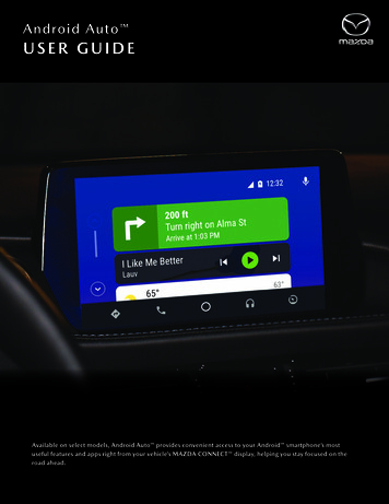
6CHAPTER 33 METHODOLOGY3.1Software ImplementationBefore starting off the project, there are a few configuration steps to be executed.Firstly the latest Java JDK has to be installed. This is to make sure that the computerhas the latest updated version of Java JDK. The Java JDK completes the wholepackage because it provides all the necessary programming tools such as the javacompiler (javac), java debugger (jdb) and many other important utilities to ensure theproper performance of the Android integrated development environment. These willallow developers to fully establish a complete Android application on a Javaplatform.Figure 3.1: Java JDK installation
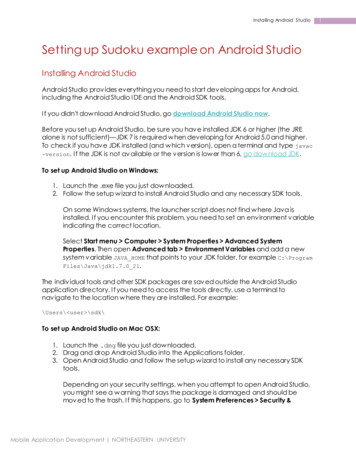
7Once this is done, the main Android application development software which is theAndroid Studio is then installed. Android studio will be used primarily to programand write the client (application).Figure 3.2: Android Studio installation pageOn the server side, MySQL database is used in conjunction with PHP as theserver-side scripting. MySQL is a relational database management system whereby itallows users to create, update, delete and administer a database for storing importantinformation in a form of a table. PHP is an abbreviation for Hypertext Preprocessorwhich serves as a bridge to send and retrieve data from the client (Androidsmartphone) to the MySQL database and vice versa.PHP is also used to send and retrieve data from the server (PC) to thedatabase as well as to store information. In order to achieve this, a web developmentenvironment called WAMP server has to be installed. WAMP is an abbreviation ofWindows, Apache, MySQL and PHP. WAMP server is an easy to use applicationwhich integrates Apache, PHP and MySQL all into a single web tool. This allowsdevelopers to easily create and manage databases through a built-in function knownas PhpMyAdmin.
8Figure 3.3: WampServer installationOn top of that, another separate IDE which is the Eclipse IDE for Javadevelopers has to be installed. Eclipse will be the main building block to programand write the server which is also the central processing as well as the control unit ofthe whole system.Figure 3.4: Eclipse IDE for Java Developers download.3.2Hardware ImplementationThe whole hardware prototype will consist of an Android mobile phone, personalcomputers (PC) and an electro-magnetic door lock circuit. The reason why PCs areused is because in every laboratory, there would already be a PC sitting inside andthus this will help minimizes the cost of setting up any additional hardware
9connections. There will be a main PC which acts as a server that coordinates therequest signals from users to unlock a specific door lock connected to their respectivecomputers.All of these signals will be transmitted through Wi-Fi and routed to theirrespective locks based on their assigned unique IP addresses. Each of the electromagnetic lock circuits are connected to the PC via the serial port also known as theRS-232 port.3.3Process FlowFigure 3.5: Process flow of operation
10The targeted users of this application would be the university students. Before usingthe door-lock application, every student will be required to have their individualsubscriber identity module (SIM) card number registered for their account into thedatabase. This can be done by registering with the authorised technician in-charge ofthe Android-based door lock system in the university.Once that is done, the application can now be used. At this point, the systemwould be able to recognize the users based on their SIM card number registered.Users will have to first register a password for their account which will be used tolog in into the application. When users key in their passwords, the application wouldcheck with the database to see if the password matches. On top of that, the systemwould also verify if the SIM card serial number matches with the database. It meansthat only authorised phones will be allowed and non-authorised phone will have noaccess to the application. This is to ensure that only the right person with the rightdevice can have access to a particular door.Once the user has successfully logged into their account, they will berequested to scan the QR code which is located at every entrance of the laboratories.When a particular QR code is scanned, the application would know exactly whichroom the user is located at and the necessary control signal would be sent over acrossWi-Fi to the central server PC which would then re-route the signal to the designatedIP address of the PC to which the lock is connected to. The lock then unlocks toprovide access.To tighten the security, all access through the doors will be recorded andstored in the MySQL database. In addition to that, the passwords will be hashed onthe client-side before being sent over to the server for storage in the database.Hashing is also known as a one-way encryption whereby the encryption of aparticular data cannot be decrypted to retrieve its original content. It also means thatwe will never know the true content of a hashed string.A typical hashing algorithm takes in an input message and then converts itinto a fixed size alphanumeric string which is also known as the hash value or
11message digest. This is a standard procedure whereby passwords are not encouragedto be stored as plaintext to protect user’s information from being stolen. Besides that,passwords are not being transmitted in plaintext but instead it is hashed before beingsent over to the database. This helps to prevent hackers from intercepting thetransmission mid-way and ultimately prevent them from stealing the information.
12CHAPTER 44 RESULTS AND DISCUSSION4.1Detailed flowchart of operation
13Figure 4.1: Detailed flowchart of operation4.2Android phone key applicationFigure 4.2: Login Screen
14Figure 4.3: Login screenFigure 4.4: Login Screen
15Figure 4.5: Login ScreenFigure 4.6: Registration Screen
16Figure 4.7: Registration ScreenFigure 4.8: Registration Screen
17Figure 4.9: Password change screenFigure 4.10: QR code opening screen
18Figure 4.11: QR code scanning screenFigure 4.12: Android Phone Key system prototype
19Figure 4.1 shows the detailed flowchart of the entire operation. Figure 4.2 shows thelogin screen of the application. Figure 4.3, figure 4.4 and figure 4.5 shows the errorsthat occur at the application’s login screen. Figures 4.6, 4.7 and 4.8 show theregistration screen. Figure 4.9 shows the password change screen. Figure 4.10 andFigure 4.11 shows the QR code screens. Figure 4.12 illustrates the Android phonekey system prototype.4.3Interfacing Android application with PCIn order for the Android application (client) to communicate with the PC (server),network programming has to be implemented. Two separate programs have beenwritten whereby the application is written using Android Studio while the serverprogram is written using Eclipse. Java has a java.net package which contains all thenecessary classes to implement the necessary network programming specificallySocket programming in this case. In order for the communication to occur, both thedevices (Android smartphone & Laptop) have to be connected to the same Wi-Finetwork. The client will first create a socket and attempts to connect that socket to aserver by specifying the targeted IP address and port number. At the same time, theserver will be invoking the accept() method whereby it will be waiting until a clientis connected to the server. Once the connection is established, both devices can sendand receive data between each other through the input and output streams of thesocket.Figure 4.13: Socket connection establishment code segment
204.4Serial Port Interfacing between PC and Door Lock CircuitThe PC is connected to the door lock circuit via the RS232-USB converter cable. Inorder for the PC to communicate with the lock circuit through the serial port, anexternal library called ‘serial communication manager (scm)’ was used. Serialcommunication manager is a Java library for communication over serial port. Thislibrary is easy and simple to use as the documentation made by the author is veryclear and concise. After importing this external library into the program, a simpleprogram was written to output a pulse through the RS232 Tx pin 3 whenever aspecific input from the Android application was received.Figure 4.14: Opening Serial COM port code segmentFrom the figure above, it can be seen that the pulse output was set to be held for abrief moment of 3000ms or 3 seconds. A typical RS232 port contains 9 pins. Whenthe RS232 port pin was engaged, the voltage of the TXD pin (pin 3) with respect toground (pin 5) was measured to be around 5V. The output voltage from Pin 3 of theRS232 serial port is used as the signal to control the door lock circuit which will beexplained in detail further in this report.
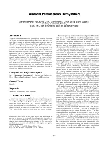
214.5Electro-magnetic lock circuit working principle12 V PowerSupplyTo EMRelaySignal from PC(Green wire)NPN TransistorLEDFigure 4.15: Door lock CircuitLock
22Signalfrom PCElectromagnetic lockFigure 4.16: Door Lock circuit schematicFigure 4.16 shows the schematic diagram of the lock circuit. The electro-magneticlock circuit was constructed by using a combination of 12 V single pole doublethrow (SPDT) relay and an NPN transistor which acts as a switch that will only betriggered when a request signal is sent from the client (Android smartphone) to theserver (PC). Once the request signal is received and processed, the server will thensend control signals through the RS232-USB cable to the base junction of the NPNtransistor which will then saturate the NPN transistor thus allowing current to flowthrough from the collector to the emitter junction of the transistor and magnetize thecoil in the relay. Once the coil is magnetized, the switch will be pulled over to theother side hence disjointing the current flow from the voltage source to the electromagnetic lock causing it to unlock the door. At the same time, the LED will light upto indicate that the lock is unlocked.
234.5.1Single Pole Double Throw Relay Working PrincipleFigure 4.17: Single Pole Double Throw Relay SchematicFigure 4.17 shows the schematic of a single pole double throw relay. Theelectromagnetic lock used in this project is a fail-safe magnetic lock which willmagnetize when a voltage of 12 Volts is supplied to it. The lock is connected to thenormally closed (NC) terminal of the relay with a voltage of 12 Volts supplied to theCOM terminal. This enables the lock to stay magnetized hence keeping the doorlocked. When the necessary control signals are transmitted and received, current willbe able to flow through and magnetize the coil in the relay hence pulling the switchover to the normally open (NO) terminal of the relay causing the current to flowtowards the LED connected at the NO terminal. During this period, no current is ableto flow through the electromagnetic lock causing the lock to de-magnetize and thedoor is unlocked.
244.5.2NPN Transistor working principleFigure 4.18: NPN transistor schematicThe transistor used in this project is a general purpose NPN transistor 2N2222. It isused as a switch to turn on a load (electromagnetic lock) which requires a largervoltage than a computer can handle. The electromagnetic lock is directly connectedto the power supply whereas the NPN transistor acts as a switch that is grounded.The maximum voltage supplied from the RS232 port of the PC is only up to 5 Voltswhich is not enough to power up and magnetize the coil of the 12 V relay used. Thiswould lead to the electromagnetic lock being magnetized continuously. Therefore,the utilization of an NPN transistor solves the issue by allowing the 5 Volts from theRS232 port to flow into the base junction of the transistor and drive it into saturationstate. Once the transistor is saturated, the current will be able to flow through thecollector-emitter junction and magnetize the relay coil which will then de-magnetizethe magnetic lock hence unlocking the door. According to the datasheet of the NPNtransistor:Figure 4.19: 2N2222 transistor datasheet
25Figure 4.20: VBE saturation for 2N2222Figure 4.21: Current gain of 2N2222The breakdown voltage at the base-emitter junction is 6V and the VBE(sat) is 0.6V. Inaddition to that, the relay coil current requires at least 33mA. Furthermore, the DCcurrent gain of the transistor is at least 35. The transistor base current can becalculated by using the equation IB IC/hFE . IB 33m/35 0.94mA which can berounded up to 1mA. By referring to Figure 4.16 with all this information, the resistorvalue R1 to be connected to the base junction of the NPN transistor can be calculated.Since the voltage supplied by the RS232 pins is around 5V, R1 (5V – 0.6V)/1ma 4400ohms. In this case, we used a 3.3k ohm resistor as we have some extra margin toensure the transistor is driven hard into saturation. There is also a resistor R3 whichis connected to the base junction of the transistor and it is grounded. It shunts thesignal from the RS232 port into the ground to prevent any current or voltage spikefrom damaging the transistor. Besides that, the resistor R3 prevents the transistorfrom turning on due to any small random voltage that may appear at the RS232 pinby draining any additional charge out from the base of the transistor. As a rule ofthumb, the resistor R3 value used is at least 10 times larger than the value of resistorR1. R2 is a 1k ohm resistor to limit the current through the LED thus preventing theLED from blowing.
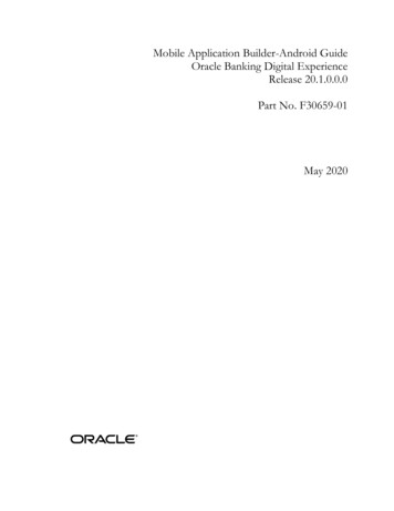
264.6Password hashingAll passwords are hashed on the client side (Android application) before being sentover to the server to be stored into the database. Initially, when a user registers for apassword, the password will be hashed and sent over to the database for storage.When a user logs in using the password, the password will be hashed again and theresulting hash value will be compared to the hash value stored previously in thedatabase. If the hash value matches, the user will be granted access. However, just byhashing alone is not sufficient to ensure reasonable protection of credentials. Thiscan easily be cracked by hackers using a rainbow table. The reason behind this isbecause, for every similar input, similar password hashes will be generated. Since arainbow table has a list of pre-computed hash functions, it is just a matter of timebefore the hacker gets to recover the plaintext password. Hence, in order to preventthe occurrence of this, salt has been prepended to the passwords before hashing themtogether to create a stronger hashing algorithm. Salt is a unique string that isconcatenated on to the passwords before the hashing algorithm takes place. Thereason why salted hashing is so useful is because it requires extra computationalpower in order to retrieve the plaintext password. In addition to that, to make it evenbetter, random salt is used instead of a fixed salt thus making it more difficult for thehackers to use a rainbow table or dictionary attack to find a collision as it is notfeasible to compute a table of all possible combinations of hashes. Besides that, evenif the hacker gets a hold of the salt string, the database wouldn’t be compromisedbecause random salt is used for every hashed password. This would result in adifferent output hash even if two same passwords are hashed with the same hashingalgorithm ultimately making it more tedious for hackers to find a collision.
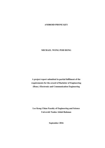
27Figure 4.22: Hashed passwordAn external library called jBCrypt was used in order to perform the hashingalgorithm above. jBCrypt is a Java implementation using Blowfish algorithm. In thisalgorithm, the salted hashing function is also iterated with proper number of roundsbefore the output hash is produced. This helps to increase the security of thepasswords as the computation time taken to find a collision would increaseexponentially.4.7Access LogsWhen a request signal to unlock a particular door is received by the server (PC), theserver will perform 2 tasks concurrently. It will send the necessary control signals tounlock the lock and at the same time it will record the access into the databasethrough PHP scripting.Every access through the door will be recorded and stored into the database.The access log contains information of the user, location, time, date, as well as everyentry and exit.
28Figure 4.23: Access log
29CHAPTER 55 CONCLUSION AND RECOMMENDATIONSThe Android-based smart locking system proposed has been developed andimplemented successfully. At the end of this project, I was able to learn, experienceand understand from the Android application developers’ point of view whendeveloping an application. It requires a great amount of dedication and criticalthinking in order to come up with a working system. Every inch of the process has tobe evaluated carefully before proceeding to write the application. Hence the processflow of the operation has to be laid out beforehand to clearly define the objectivesand goals of t
feature to allow interfacing the Arduino ADK with Android mobile phones. His research on smart home system caters more towards the disabled and senior citizens. Hao Shi has also done a research using the Android SDK, Java JDK and Android development tools to implement a home lighting system.