Transcription
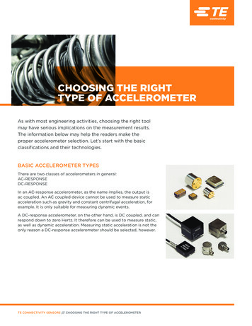
CHOOSING THE RIGHTTYPE OF ACCELEROMETERAs with most engineering activities, choosing the right toolmay have serious implications on the measurement results.The information below may help the readers make theproper accelerometer selection. Let’s start with the basicclassifications and their technologies.BASIC ACCELEROMETER TYPESThere are two classes of accelerometers in general:AC-RESPONSEDC-RESPONSEIn an AC-response accelerometer, as the name implies, the output isac coupled. An AC coupled device cannot be used to measure staticacceleration such as gravity and constant centrifugal acceleration, forexample. It is only suitable for measuring dynamic events.A DC-response accelerometer, on the other hand, is DC coupled, and canrespond down to zero Hertz. It therefore can be used to measure static,as well as dynamic acceleration. Measuring static acceleration is not theonly reason a DC-response accelerometer should be selected, however.TE CONNECTIVITY SENSORS /// CHOOSING THE RIGHT TYPE OF ACCELEROMETER
CHOOSING THE RIGHTTYPE OF ACCELEROMETERDESIGN REQUIREMENTSACCELERATION, VELOCITY, DISPLACEMENTThe majority of vibration studies require theknowledge of acceleration, velocity, and displacement- the important variables that engineers seekin designing or validating a structure. Generallyspeaking, the g value provides a good reference, butvelocity and displacement are the variables neededin most design calculations. To derive velocity anddisplacement from the acceleration output, the signalfrom the accelerometer is integrated and doubleintegrated respectively in the analog or digitaldomain. Here is where an AC-response accelerometermay run into trouble. To illustrate the problem,picture when an AC- response accelerometer is usedto measure a long duration half-sine input pulse.The output of this device can never quite track thepeak of the half-sine input because of the intrinsiclimitation imposed by its RC time constant. At the endof the half-sine pulse, the output of the ac coupledaccelerometer will produce an undershoot (offset)for the very same reason. The red trace in the figurebelow depicts the output of an AC coupled devicefollowing a long duration half-sine input.These seemingly small amplitude deviations can resultin significant errors during numerical integration. ADC-response device has no such problem becauseit can follow the slow-moving input accurately. Inreal day-to-day applications, physical inputs do notresemble half-sine impulses, but the basic problemremains whenever one needs to track slow motionwith an AC coupled device. Now, let’s look at thevarious popular accelerometer technologies.TE CONNECTIVITY SENSORS /// CHOOSING THE RIGHT TYPE OF ACCELEROMETERPAGE 2
CHOOSING THE RIGHTTYPE OF ACCELEROMETERAC ACCELEROMETERSThe most common AC-response accelerometers usepiezoelectric elements for their sensing mechanism.Under acceleration, the seismic mass of theaccelerometer causes the piezoelectric element to“displace” a charge, producing an electrical outputproportional; to acceleration.Electrically, the piezoelectric elements look like asource capacitor with a finite internal resistance,typically in the order of 109 ohms. This forms theRC time constant which defines the high-passcharacteristics of the device. For this reason,piezoelectric accelerometer cannot be used tomeasure static events. Piezoelectric elements canbe natural or man-made. They come with varyingdegrees of transduction efficiency and linearitycharacteristics.Two types of piezoelectric accelerometer are availableon the market: CHARGE OUTPUT TYPE and VOLTAGEOUTPUT TYPE.CHARGE MODE PIEZOELECTRICThe majority of the piezoelectric sensors are basedon lead zirconate titanate ceramics (PZT) whichoffer very wide temperature range, broad dynamicrange, and wide bandwidth (usable to 10kHz).When housed in a hermetic, welded metal case, acharge mode accelerometer can be considered oneof the most durable sensors because of its abilityto tolerate hostile environmental conditions. Due toits high impedance characteristics, a charge modedevice must be used with a low-noise shielded cable,preferably in a coaxial configuration. Low noise refersto low triboelectric noise2, a motion induced spuriousoutput from the cable itself. These noise- treatedcables are commonly available from the sensormanufacturers. A charge amplifier is generally used tointerface with charge mode accelerometers to avoidproblems associated with parallel cable capacitance.With a modern charge amplifier, the broad dynamicrange ( 120 dB) of the charge mode sensors can beeasily realized. Due to the wide operating temperaturerange of piezoelectric ceramics, some charge modedevices can be used from -200 C to 640 C andbeyond. They are especially suitable for use invibration measurements at temperature extremes,such as in turbine engine monitoring.VOLTAGE MODE PIEZOELECTRICThe other type of piezoelectric accelerometerprovides voltage output instead of charge.This is accomplished by incorporating the chargeamplifier inside the housing of the accelerometer.Voltage mode devices feature 3-wire (Signal, Ground,Power) mode or 2- wire (Power/Signal, Ground)mode. The 2- wire mode is also known as IntegralElectronics PiezoElectric (IEPE). IEPE is mostpopular due to its convenient coaxial (two-wire)configuration in which the ac signal is superimposedon the dc power line. A blocking capacitor is neededto remove the dc bias from the sensor signal output.Many modern signal analyzers provide the IEPE/ICP3 input option which allows a direct interface toIEPE accelerometers. If the IEPE power option is notavailable, a signal conditioner/power supply withconstant current power is required to interface withthis type of device. The 3-wire mode device requires aseparate dc power supply line for proper operation.Unlike a charge mode device that only containsceramic sensing element(s), voltage mode deviceincludes a microelectronic circuit which limits theoperating temperature of the device to the maximumoperating temperature of the electronics, usually topsat 125 C. Some designs push the limit to 175 C,but they come with compromises elsewhere in theperformance envelope.A word on usable dynamic range - Due to theexceptionally wide dynamic range in piezoelectricceramic elements, charge mode accelerometersare most flexible in terms of scalability because thesystem full scale range can be adjusted from theremote charge amplifier at the user’s command.Voltage mode devices, on the other hand, havetheir full scale range pre-determined by the internalamplifier at the factory and cannot be altered.Piezoelectric accelerometers are available in verysmall footprint. They are therefore suited for dynamicmeasurements in lightweight structures.TE CONNECTIVITY SENSORS /// CHOOSING THE RIGHT TYPE OF ACCELEROMETERPAGE 3
CHOOSING THE RIGHTTYPE OF ACCELEROMETERDC-ACCELEROMETERSfrequency motion where the g level is also low, suchas vibration measurements in civil engineering.Two popular sensing technologies are usedin making DC-accelerometers:CAPACITIVE and PIEZORESISTIVEPIEZORESISTIVECAPACITIVECapacitive type (based on the capacitance changesin the seismic mass under acceleration) is themost common technology used for accelerometertoday. They are made popular by large commercialapplications such as air-bag and mobile devices. Theyemploy Micro-Electro-Mechanical Systems (MEMS)fabrication technology which brings economy ofscale to high volume applications, hence lowermanufacturing cost. But this class of low-pricecapacitive accelerometers typically suffers from poorsignal to noise ratio and limited dynamic range. Oneinherent characteristic with all capacitive devices isits internal clock. The clock frequency ( 500kHz)is an integral part of the current detection circuit,which is invariably present in the output signal due tointernal leakage. The high frequency noise may wellbe outside of the acceleration measurement rangeof interest, but it is always there with the signal. Dueto its built-in amplifier/IC, its 3-wire (or 4- wire fordifferential output) electrical interface is straightforward, requiring only a stable DC voltage source forpower.Bandwidth of capacitive accelerometer is mostlylimited to a few hundred Hertz’s (some designs offerup to 1500Hz) partly due to its physical geometryand its heavy gas damping. Capacitive sensorstructure also favors the lower range of accelerationmeasurement. Maximum range is typically limitedto less than 200g’s. Other than these restrictions,modern capacitive accelerometers, especially theinstrument grade devices, offer good linearity andhigh output stability.Capacitive type accelerometers are most suitable foron-board monitoring applications where cost may bethe driving factor. They are suited for measuring lowPiezoresistive is the other commonly used sensingtechnology for DC-response accelerometers. Insteadof sensing the capacitance changes in the seismicmass (as in a capacitive device), a piezoresistiveaccelerometer produces resistance changes in thestrain gages that are part of the accelerometer’sseismic system. Most engineers are familiar with straingage and know how to interface with its output. Theoutput of most piezoresistive designs is generallysensitive to temperature variation. It is thereforenecessary to apply temperature compensation to itsoutput internally or externally. Modern piezoresistiveaccelerometers incorporate ASIC for all forms ofon board signal conditioning, as well as in- situtemperature compensation.Bandwidth of piezoresistive accelerometers can reachupwards of 7,000 Hz. Many of the piezoresistivedesigns are either gas damped (MEMS types) orfluid damped (bonded strain gage type). Dampingcharacteristics can be an important factor inchoosing an accelerometer. In applications where themechanical input may contain very high frequencyinput (or excite high frequency response), a dampedaccelerometer can prevent sensor ringing (resonance)and preserve or improve dynamic range. Because thepiezoresistive sensor output is differential and purelyresistive, signal to noise performance is generallyoutstanding; its dynamic range is limited only by thequality of the DC bridge amplifier. For very high gshock measurements, some piezoresistive designs canhandle acceleration levels well above 10,000g’s.Due to its broader bandwidth capability, piezoresistivetype accelerometers are most suitable for impulse/impact measurements where frequency range and glevel are typically high. Being a DC-response device,one can accurately derive from its accelerationoutput the desired velocity and displacementinformation without integration error. Piezoresistiveaccelerometers are commonly used in automotivesafety testing, weapons testing, and higher shockrange measurements beyond the usable range of VCaccelerometers.TE CONNECTIVITY SENSORS /// CHOOSING THE RIGHT TYPE OF ACCELEROMETERPAGE 4
CHOOSING THE RIGHTTYPE OF ACCELEROMETERSUMMARYEach accelerometer sensing technology has itsadvantages and compromises. Before making aselection, it’s important to understand the basicdifferences of the various types and the testrequirements.First and foremost, choose only DC-responseaccelerometers to measure static or very lowfrequency ( 1Hz) acceleration, or if velocity anddisplacement information are to be extractedfrom the acceleration data. Both DC and ACresponse accelerometers are capable of measuringdynamic events. When dealing only with dynamicmeasurement, the choice between a DC or ACresponse device is really a matter of preference. Someusers don’t like to deal with the zero offset of a DCresponse sensor and prefer the ac coupled, singleended output of the piezoelectric types. Others don’tmind dealing with the zero offset and four wires (or3-wire if in single-ended mode) and like the shuntcalibration and built- in functional test (2g turnover)capabilities of DC-response accelerometers. Insummary:Charge mode piezoelectric design is the most durableaccelerometer type due to its simple construction androbust material properties.For high temperature ( 150 C) dynamic measurementapplications, charge mode piezoelectric is an obviouschoice; or in most cases, the only choice. With chargemode device, a low-noise coaxial cable should beused due to its high impedance output, and a remotecharge amplifier (or an inline charge converter) tocondition its charge output.Voltage mode piezoelectric is the most popular typeof accelerometer for dynamic measurements. It offerssmall size, broad bandwidth and a built-in chargeconverter which allows direct interface with manymodern signal analyzers and data acquisition systems(those that offer integrated IEPE/ICP power source).Voltage mode piezoelectric is typically limited to 125 C applications, but it is no longer necessaryto use a low-noise coaxial cable due to its lowimpedance output.Capacitive design features critically damped tooverdamped response which lends itself to lowfrequency measurements. The low cost, SMD classof devices is suited for high volume automotive andconsumer applications where ultimate accuracy isnot a priority. The more expensive instrumentationgrade silicon MEMS capacitive accelerometers havegood bias stability and very low noise. Capacitiveaccelerometers have low impedance output and 2V to 5V full scale output. Most designs require aregulated dc voltage for power.Piezoresistive accelerometers are versatile in terms oftheir frequency and dynamic range capabilities. Beinga DC-response device, it can handle static accelerationand produce accurate velocity and displacementdata. Its broad bandwidth also covers most dynamicmeasurement needs. Piezoresistive designs offervarious degree of damping (from ζ 0.1 to 0.8)response which makes it suitable for use in a varietyof test conditions, including shock testing. Plainpiezoresistive accelerometers (without electronics)are small and lightweight, with a 100 to 200mVfull scale output. The amplified models (with built-inASIC) feature low output impedance ( 100Ω) and 2Vto 5Vfull scale output.TE CONNECTIVITY SENSORS /// CHOOSING THE RIGHT TYPE OF ACCELEROMETERPAGE 5
REFERENCES1. A. G. Piersol, T.L. Paez, Harris’ Shock and Vibration Handbook 6th Ed., p.10.9, McGraw-Hill, 20102. A. G. Piersol, T.L. Paez, Harris’ Shock and Vibration Handbook 6th Ed., p.15.19, McGraw-Hill, 20103. ICP is a registered trademark of PCB. Other popular trade names from various suppliers existte.com/sensorsolutionsMeasurement Specialties, Inc., a TE Connectivity company.MEAS, TE Connectivity, TE Connectivity (logo) and Every Connection Counts are trademarks. All other logos,products and/or company names referred to herein might be trademarks of their respective owners.The information given herein, including drawings, illustrations and schematics which are intended for illustrationpurposes only, is believed to be reliable. However, TE Connectivity makes no warranties as to its accuracy orcompleteness and disclaims any liability in connection with its use. TE Connectivity‘s obligations shall only beas set forth in TE Connectivity‘s Standard Terms and Conditions of Sale for this product and in no case will TEConnectivity be liable for any incidental, indirect or consequential damages arising out of the sale, resale, useor misuse of the product. Users of TE Connectivity products should make their own evaluation to determine thesuitability of each such product for the specific application. 2017TE Connectivity Ltd. family of companiesAll Rights Reserved.CHOOSING THE RIGHT TYPE OF ACCELEROMETER07/17OriginalTE CONNECTIVITY SENSORS /// CHOOSING THE RIGHT TYPE OF ACCELEROMETERTE CONNECTIVITYFor More Information ContactTE om
CHOOSING THE RIGHT TYPE OF ACCELEROMETER TE CONNECTIVITY SENSORS /// CHOOSING THE RIGHT TYPE OF ACCELEROMETER As with most engineering activities, choosing the right tool may have serious implications on the measurement results. The information below may help the readers make the proper accelerometer selection. Let's start with the basic


