Transcription
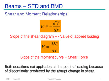
Beams – SFD and BMDShear and Moment RelationshipsdVw dxSlope of the shear diagram - Value of applied loadingdMV dxSlope of the moment curve Shear ForceBoth equations not applicable at the point of loading becauseof discontinuity produced by the abrupt change in shear.ME101 - Division IIIKaustubh Dasgupta1
Beams – SFD and BMDw dVdxdMV dxDegree of V in x is one higher than that of wDegree of M in x is one higher than that of V Degree of M in x is two higher than that of wd 2M wCombining the two equations 2dx M :: obtained by integrating this equation twice Method is usable only if w is a continuous function of x (othercases not part of this course)ME101 - Division IIIKaustubh Dasgupta2
Beams – SFD and BMDShear and Moment RelationshipsExpressing V in terms of w by integrating w Vx00 V dV x wdxORdVdxV V0 (the negative of the area underthe loading curve from x0 to x)V0 is the shear force at x0 and V is the shear force at xExpressing M in terms of V by integrating V dMMx00 M dM x VdxdxOR M M0 (area under the shear diagramfrom x0 to x)M0 is the BM at x0 and M is the BM at xME101 - Division IIIKaustubh Dasgupta3
Beams – SFD and BMDV V0 (negative of area under the loading curve from x0 to x)M M0 (area under the shear diagram from x0 to x)If there is no externally applied moment M0 at x0 0,total moment at any section equals the area underthe shear diagram up to that sectionWhen V passes through zero and is a continuousfunction of x with dV/dx 0 (i.e., nonzero loading)dM 0dx BM will be a maximum or minimum at this pointCritical values of BM also occur when SF crosses the zero axisdiscontinuously (e.g., Beams under concentrated loads)ME101 - Division IIIKaustubh Dasgupta4
Beams – SFD and BMD: Example (1) Draw the SFD and BMD. Determine reactions atsupports. Cut beam at C and considermember AC,V P 2 M Px 2 Cut beam at E and considermember EB,V P 2 M P L x 2 For a beam subjected toMaximum BM occursconcentrated loads, shear iswhere Shear changes theconstant between loadingdirectionpoints and moment varieslinearlyME101 - Division IIIKaustubh Dasgupta5
Beams – SFD and BMD: Example (2)Draw the shear and bending moment diagrams for the beam and loading shown.Solution: Draw FBD and find out thesupport reactions usingequilibrium equationsME101 - Division IIIKaustubh Dasgupta6
SFD and BMD: Example (2)Use equilibrium conditions at all sections toget the unknown SF and BMV1 20 kN Fy 0 : 20 kN V1 0 M1 0 : 20 kN 0 m M1 0M1 0V2 -20 kN; M2 -20x kNmV3 26 kN; M3 -20x 46 0 -20x MB -50 kNmV4 26 kN; M4 -20x 46 (x-2.5) MC 28 kNmV5 -14 kN; M5 -20x 46 (x-2.5)-40 0 MC 28 kNmV6 -14 kN; M6 -20x 46 (x-2.5)-40 (x-5.5) MD 0 kNmME101 - Division IIIKaustubh Dasgupta7
Beams – SFD and BMD: Example (3)Draw the SFD and BMD for the beamacted upon by a clockwise couple atmid pointClSolution: Draw FBD of the beam andCalculate the support reactionsCClVDraw the SFD and the BMD startingFrom any one end ClMC2 ME101 - Division IIIKaustubh DasguptaC28
Beams – SFD and BMD: Example (3)Draw the SFD and BMD for the beamSolution: Draw FBD of the beam andCalculate the support reactions60 N MA 0 RA 60 N MB 0 RB 60 NVDraw the SFD and the BMD startingfrom any one end120 Nm60 N-60 NM-120 NmME101 - Division IIIKaustubh Dasgupta9
Beams – SFD and BMD: Example (4)Draw the SFD and BMD for the beamSolution:Draw FBD of the entire beamand calculate support reactionsusing equilibrium equationswReactions at supports:R A RB wL2Develop the relations between loading, shear force, and bendingmoment and plot the SFD and BMDME101 - Division IIIKaustubh Dasgupta10
Beams – SFD and BMD: Example (4)Shear Force at any section: V wwL L wx w x 2 2 xAlternatively, V V A w dx wx0wL L V V A wx wx w x 2 2 wLx wx wx L x x2BM at any section: M 22 2xAlternatively, M M A Vdx0 w L M w x dx L x x22 0 2xM maxME101 - Division IIIwL2 8Kaustubh Dasgupta dM M at V 0 dx 11
Beams – SFD and BMD: Example (5)Draw the SFD and BMD for the BeamArea under SFDSolution:SFD and BMD can be plotted withoutdetermining support reactions sinceit is a cantilever beam.However, values of SF and BM can beverified at the support if supportreactions are known.waw a a w aRC 0 ; M C 0 L 0 3L a 22 3 6ME101 - Division IIIKaustubh DasguptaM12
Beams – SFD and BMD: Summary2.5 m3m2mSFDBMDw2ml/22mLl/2SFDBMDME101 - Division IIIKaustubh Dasgupta13
Beams – Internal EffectsExample: Find the internal torques at points B and C of the circular shaftsubjected to three concentrated torquesSolution: FBD of entire shaftSections at B and C and FBDs of shaft segments AB and CDME101 - Division IIIKaustubh Dasgupta14
CablesFlexible and Inextensible hME101 - Division IIIKaustubh Dasgupta15
Cables Relations involving Tension, Span, Sag, and Length are reqd– Obtained by examining the cable as a body in equilibrium It is assumed that any resistance offered to bending isnegligible Force in cable is always along the direction ofthe cable. Flexible cables may be subjected to concentrated loads ordistributed loadsME101 - Division IIIKaustubh Dasgupta16
Cables In some cases, weight of the cable isnegligible compared with the loads itsupports. In other cases, weight of the cable maybe significant or may be the only loadacting weight cannot be neglected.Three primary cases of analysis: Cables subjected to1. concentrated load, 2. distributed load, 3. self weight Requirements for equilibrium are formulated in identical wayprovided Loading is coplanar with the cableME101 - Division IIIKaustubh Dasgupta17
CablesPrimary Assumption in Analysis:The cable is perfectly Flexible and InextensibleFlexible cable offers no resistance to bending tensile force acting in the cable is always tangentto the cable at points along its lengthInextensible cable has a constant length both before andafter the load is applied once the load is applied, geometry of the cableremains fixed cable or a segment of it can be treated as arigid bodyME101 - Division IIIKaustubh Dasgupta18
CablesGeneral RelationshipsEquilibrium of the element:Simplifying using trigonometric expansions and dropping second order termsFurther simplifying: Finally:whereME101 - Division III Equilibrium Equation Differential Equation for the Flexible Cable-Defines the shape of the cable-Can be used to solve two limiting cases of cable loadingKaustubh Dasgupta19
Cables: Parabolic CableParabolic CableIntensity of vertical loading is constant It can be proved that the cable hangsin a Parabolic Arc Differential Equation can be used to analyseME101 - Division IIIKaustubh Dasgupta20
Cables: Catenary CableCatenary CableHanging under the action of its own weight It can be proved that the cable hangsin a curved shape called Catenary Differential Equation can be used to analyseμ is the self weight per unit lengthME101 - Division IIIKaustubh Dasgupta21
Beams -SFD and BMD Shear and Moment Relationships Expressing V in terms of w by integrating OR V 0 is the shear force at x 0 and V is the shear force at x Expressing M in terms of V by integrating OR M 0 is the BM at x 0 and M is the BM at x V V 0 (the negative of the area under ³ ³ the loading curve from x 0 to x) x x V V dV wdx 0 0 dx dV w dx dM V ³ ³ x x M M dM x 0 0 M M 0 .