Transcription
543-0033-00, 943-0033-00User’s Manual1
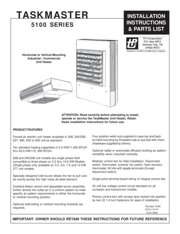
Comfort Alert Diagnostics – Faster Service And Improved AccuracyThe Comfort Alert diagnostics module is a breakthrough innovation for troubleshootingheat pump and air conditioning system failures. The module installs easily in the electricalbox of the outdoor unit near the compressor contactor. By monitoring and analyzingdata from the Copeland Scroll compressor and the thermostat demand, the modulecan accurately detect the cause of electrical and system related failures without anysensors. A flashing LED indicator communicates the ALERT code and guides the servicetechnician more quickly and accurately to the root cause of a problem.NOTE: This module does not provide safety protection! The Comfort Alert moduleis a monitoring device and cannot shut down the compressor directly.LED Description (Figure 1)POWER LED (Green): indicates voltage is present atthe power connection of the module.ALERT LED (Yellow): communicates an abnormal systemcondition through a unique flash code. The ALERT LEDwill flash a number of times consecutively, pause and thenrepeat the process. The number of consecutive flashes,defined as the Flash Code, correlates to a particularabnormal condition. Detailed descriptions of specificALERT Flash Codes are shown in two tables on pages 8and 9 of this manual.TRIP LED (Red): indicates there is a demand signal fromthe thermostat but no current to the compressor is detectedby the module. The TRIP LED typically indicates thecompressor protector is open or may indicatemissing supply power to the compressor.Product SpecificationsOperating Temperature:Storage Temperature:Power Supply Range:Power Requirement:UL Restrictions:Figure 1-40 to 150 F (-40 to 65 C)-40 to 175 F (-40 to 80 C)UL File #SA895818-30VAC, 48-62 Hz1.5 VA nominal (without solenoid on)6.0VA nominal (with solenoid on)Use only with Class 2 circuits.This Comfort Alert module is designed only for single-phase systems with Copelandscroll compressors that have internal overload protection. The software in this ComfortAlert module has been optimized for two stage UltraTech scroll systems.2
Module Dimensions (Figure 2):A.B.C.1.85 in (47 mm)2.44 in (62 mm)1.46 in (37 mm)D.E.4.40 in (112mm)2.44 in (62 mm)Figure 2Hazardous voltage inside air conditioning system.Disconnect power before installing or servicing module.WARNINGModule must be installed and serviced only by qualifiedpersonnel.Hardware InstallationFour #8 or #10 self drilling or sheet metal screws, at least ½” length, are required forinstallation of the Comfort Alert module. The maximum screw torque is 20 in.-lbs. Locatethe Comfort Alert module near the compressor contactor (wire routing for compressorrun, common and start wires will be easier in this position). Mount the Comfort Alertmodule so all LEDs are visible from a comfortable viewing position. The module willoperate in any mounting orientation. For ease of reading labels, the module should beoriented so that the green POWER LED is at the top.3
Compressor Wire Routing (Figure 3)The scroll compressor’s run (R), common (C) and start (S) wires are routed through theholes in the Comfort Alert module marked “R,” “C” and “S.” The common (C) wire neednot be routed through the module for it to operate properly.24VAC Power WiringThe Comfort Alert module requiresa constant nominal 24VAC powersupply. The wiring to the module’s Rand C terminals must be directly fromthe indoor unit or thermostat. Themodule cannot be powered by the Cterminal on a defrost board or othercontrol board without experiencingnuisance alerts. Refer to Figure 5.Figure 3When constant 24VAC (R wire) is notpresent in the outdoor unit, use one ofthe spare wires in the thermostat cableto bring power to the module. Connectthe other end of the spare wire to R atthe indoor unit or thermostat. Refer towiring schematic in Figure 4 and 5.Thermostat Demand WiringThe Comfort Alert module requires a thermostat demand signal to operate properly. Thethermostat demand signal input, labeled Y on the module, should always be connectedto the compressor contactor coil so that when the coil is energized, the demand signalinput is 24VAC. When the coil is not energized, the demand signal input should be lessthan 0.5VAC.NOTE: Factory installed modules may have different thermostat demand signalwiring. Follow manufacturer’s wiring instructions when replacing module.NOTE: After the thermostat demand signal is connected, verify Y is phasedproperly with C by measuring 24VAC across Y and C when demand is present.4
CCHPCOHTCORLY1LY1LPCOY2YComfort AlertDiagnosticsModule543-0033-00LRCDC SOLUltra TechSolenoid529-0369-00Y2CY2CIndoor UnitTerminal BlockRTwo Stage Indoor ThermostatFigure 4 Air Conditioning SchematicSchematic Abbrevation DescriptionsHTCO High Temperature Cut Out SwitchHPCO High Pressure Cut Out SwitchCC Compressor ContactorLPCO Low Pressure Cut Out SwitchCCHPCOHTCOLPCOY2YComfort AlertDiagnosticsModule543-0033-00LDefrostBoardRCDC SOLUltra TechSolenoid529-0369-00Y2CY2CRLY1LY1Indoor UnitTerminal BlockRTwo Stage Indoor ThermostatFigure 5 Heat Pump Schematic5
Thermostat Second Stage Cooling WiringThis Comfort Alert module requires a two stage thermostat to operate properly. TheY2 thermostat wire coming into the outdoor unit should be connected to the Y2 inputon Comfort Alert.While the compressor is running, Comfort Alert will provide power to the second stagecooling solenoid inside the compressor after Y2 has been energized for 5 seconds.Whenever the compressor is not running, Comfort Alert will not power the solenoid,regardless of the state of Y2. If Alert codes 1 or 9 appear while the compressor isrunning, Comfort Alert will turn off the solenoid to prevent solenoid damage fromoverheating conditions.L Terminal WiringThe L connection is used to communicate Alert codes to compatible White-Rodgersthermostats. The L terminal of the thermostat should be connected directly to the ComfortAlert L terminal.On select White-Rodgers thermostats, an icon on the thermostat display will flash atthe same rate as the Comfort Alert yellow Alert LED. An advanced option on thesethermostats is to lock out the compressor when certain Alert codes are detected indicatingimpending compressor damage. Refer to White-Rodgers thermostat manuals for moreinformation.DC SOL ConnectionThe two pin DC SOL connector provides a connection to the Copeland UltraTechsecond stage compressor solenoid. This solenoid is internal to the compressor. This24VDC solenoid will not operate properly if 24VAC is applied to the compressor solenoidterminals.To reduce the VA load of the solenoid on the system, Comfort Alert uses a phase controlmethod to reduce the DC voltage to the solenoid to the minimum level required to keepthe solenoid pulled in. As the 24VAC supply voltage varies, Comfort Alert intelligentlychanges the solenoid DC voltage supply to minimize power consumption. A voltmeterattached to the DC SOL output will measure 4-18VDC, when solenoid should beenergized, depending on the level of the 24VAC supply.6
Interpreting The Diagnostic LEDsWhen an abnormal system condition occurs, the Comfort Alert module displays theappropriate ALERT and/or TRIP LED. The yellow ALERT LED will flash a number oftimes consecutively, pause and then repeat the process. To identify a Flash Codenumber, count the number of consecutive flashes. Every time the module powersup, the last ALERT Flash Code that occurred prior to shut down is displayed for oneminute.Installation VerificationTo verify the installation of Comfort Alert is correct, two functional tests can be performed.Disconnect power from the compressor and force a thermostat call for cooling. The redTrip LED should turn on indicating a compressor trip as long as 24VAC is measured atthe Y terminal. If the red LED does not function as described, refer to Table 1 to verifythe wiring.Disconnect power from the compressor and 24VAC from Comfort Alert. Remove thewire from the Y terminal of Comfort Alert, reapply 24VAC power to Comfort Alert andreconnect power to the compressor. Force a thermostat call for cooling and when theCompressor starts to run, the yellow Alert LED will begin flashing a Code 8 indicatinga Welded Contactor. Disconnect power from the compressor and 24VAC from ComfortAlert. While Comfort Alert is off, reattach the wire to the Y terminal. Reapply power tocompressor and 24VAC to Comfort Alert, the yellow Alert LED will flash the previouscode 8 for 1 minute and then turn off. If the yellow LED does not function as described,refer to Table 1 to verify the wiring.Troubleshooting The InstallationDepending on the system configuration, some ALERT Flash codes may not be active.The presence of safety switches affects how the system alerts are displayed by thismodule. Refer to Figures 4 & 5 for safety switch wiring.Resetting Alert CodesAlert codes can be reset manually and automatically. The manual method to reset an Alertcode is to cycle the power to Comfort Alert off and on. For automatic reset, Comfort Alertcontinues to monitor the compressor and system after an Alert is detected. If conditionsreturn to normal, the Alert code is turned off automatically.Comfort Alert Part NumbersOEM P/NService P/NCopeland Scroll Compressor Application543-0010-00943-0010-00Single Stage Air Conditioning543-0012-00943-0012-00All Heat Pump and Two Stage A/C543-0032-00943-0032-00Single Stage A/C & Heat Pump543-0033-00943-0033-00Two Stage A/C & Heat Pump7
8Status LEDStatus LED DescriptionStatus LED Troubleshooting InformationGreen “POWER”Module has powerSupply voltage is present at module terminalsRed “TRIP”Thermostat demand signal Y ispresent, but the compressor isnot running1.Compressor protector is open Check for high head pressure Check compressor supply voltage2.Outdoor unit power disconnect is open3.Compressor circuit breaker or fuse(s) is open4.Broken wire or connector is not making contact5.Low pressure switch open if present in system6.Compressor contactor has failed openYellow “ALERT”Flash Code 1Long Run Time Compressoris running extremely long runcycles1.Low refrigerant charge2.Evaporator blower is not running Check blower relay coil and contacts Check blower motor capacitor Check blower motor for failure or blockage Check evaporator blower wiring and connectors Check indoor blower control board Check thermostat wiring for open circuit3.Evaporator coil is frozen Check for low suction pressure Check for excessively low thermostat setting Check evaporator airflow (coil blockages or return air filter) Check ductwork or registers for blockage4.Faulty metering device Check TXV bulb installation (size, location and contact) Check if TXV/fixed orifice is stuck closed or defective5. Condenser coil is dirty6. Liquid line restriction (filter drier blocked if present in system)7. Compressor Second Stage Cooling Wiring Solenoid plug not connected Y2 not wired at Comfort Alert8. Thermostat is malfunctioning Check thermostat sub-base or wiring for short circuit Check thermostat installation (location, level)9.Comfort Alert failureYellow “ALERT”Flash Code 2System Pressure TripDischarge or suctionpressure out of limits orcompressor overloaded1. High head pressure Check high pressure switch if present in system Check if system is overcharged with refrigerant Check for non-condensable in system2. Condenser coil poor air circulation (dirty, blocked, damaged)3.Condenser fan is not running Check fan capacitor Check fan wiring and connectors Check fan motor for failure or blockage4.Return air duct has substantial leakage5.If low pressure switch present in system, check FlashCode 1 information
Status LEDStatus LED DescriptionStatus LED Troubleshooting InformationYellow “ALERT”Flash Code 3Short CyclingCompressor is runningonly briefly1. Thermostat demand signal is intermittent2. Time delay relay or control board defective3. If high pressure switch present go to Flash Code 2 information4. If low pressure switch present go to Flash Code 1 informationYellow “ALERT”Flash Code 4Locked Rotor1.Run capacitor has failed2.Low line voltage (contact utility if voltage at disconnect is low) Check wiring connections3.Excessive liquid refrigerant in compressor4.Compressor bearings are seized Measure compressor oil levelYellow “ALERT”Flash Code 5Open Circuit1.Outdoor unit power disconnect is open2.Compressor circuit breaker or fuse(s) is open3.Compressor contactor has failed open Check compressor contactor wiring and connectors Check for compressor contactor failure (burned, pitted or open) Check wiring and connectors between supply and compressor Check for low pilot voltage at compressor contactor coil4.High pressure switch is open and requires manual reset5.Open circuit in compressor supply wiring or connections6.Unusually long compressor protector reset time due toextreme ambient temperature7.Compressor windings are damaged Check compressor motor winding resistanceYellow “ALERT”Flash Code 6Open Start CircuitCurrent only in run circuit1.Run capacitor has failed2.Open circuit in compressor start wiring or connections Check wiring and connectors between supply and thecompressor “S” terminal3.Compressor start winding is damaged Check compressor motor winding resistanceYellow “ALERT”Flash Code 7Open Run CircuitCurrent only in start circuit1.Open circuit in compressor run wiring or connections Check wiring and connectors between supply and thecompressor “R” terminal2.Compressor run winding is damaged Check compressor motor winding resistanceYellow “ALERT”Flash Code 8Welded ContactorCompressor always runs1.Compressor contactor has failed closed2.Thermostat demand signal not connected to moduleYellow “ALERT”Flash Code 9Low VoltageControl circuit 17VAC1.Control circuit transformer is overloaded2.Low line voltage (contact utility if voltage at disconnect is low) Check wiring connectionsFlash Code number corresponds to a number of LED flashes, followed by a pause and then repeated.TRIP and ALERT LEDs flashing at same time means control circuit voltage is too low for operation.9
NOTE: The correct Comfort Alert model must be used for the application (referto the Product Specification section on pages 2 and 3). If the wrong model isinstalled, the ALERT Flash Codes for system faults will function incorrectly: theComfort Alert module may indicate system faults that are not present or fail toindicate system faults that are present.NOTE: Miswiring the Comfort Alert module will cause false LED codes. Table 1describes LED operation when the module is miswired and what troubleshootingaction is required to correct the problem.Miswired Module IndicationRecommended Troubleshooting ActionGreen LED is not on,module does not power upDetermine if both R and C module terminals areconnected. Verify voltage is present at module’s R andC terminals. Review 24VAC Power Wiring (page 4) forR and C wiring.Determine if R and Y terminals are wired in reverse.Verify module’s R and C terminals have a constantsource. Review 24VAC Power Wiring (page 4) for Rand C wiring.Green LED intermittent,module powers up onlywhen compressor runsTRIP LED is on but systemand compressor check OKTRIP LED and ALERT LEDflashing togetherALERT Flash Code 3(Compressor Short Cycling)displayed incorrectlyALERT Flash Code 5, 6 or 7(Open Circuit, Open Start Circuitor Open Run Circuit) displayedincorrectlyALERT Flash Code 6 (OpenStart Circuit) displayed for Code 7(Open Run Circuit) or vice versaALERT Flash Code 8(Welded Contactor)displayed incorrectlyVerify Y terminal is connected to 24VAC at contactorcoil. Verify voltage at contactor coil falls below 0.5VACwhen off. Verify 24VAC is present across Y and C whenthermostat demand signal is present. If not, R and C arereverse wired.Verify R and C terminals are supplied with 19-28VAC.Verify Y terminal is connected to 24VAC at contactor coil.Verify voltage at contactor coil falls below 0.5VAC whenoff.Check that compressor run and start wires are throughmodule’s current sensing holes. Verify Y terminal isconnected to 24VAC at contactor coil. Verify voltage atcontactor coil falls below 0.5VAC when off.Check that compressor run and start wires are routedthrough the correct module sensing holes.Determine if module’s Y terminal is connected. Verify Yterminal is connected to 24VAC at contactor coil. Verify24VAC is present across Y and C when thermostatdemand signal is present. If not, R and C are reversewired. Verify voltage at contactor coil falls below 0.5VACwhen off. ReviewThermostat Demand Wiring (page 4) forY and C wiring.Table 110
Warranty InformationCopeland Corporation warrants its enclosed diagnostic module to be free from defects inmaterials and workmanship under normal use for a period of one year from the date ofpurchase or twenty months from manufacture whichever comes first. During this period,Copeland Corporation will replace any defective diagnostic module without charge.This warranty is valid for the original purchaser from the date of initial purchase and isnot transferable. Keep the original sales receipt. Proof of purchase is required to obtainwarranty replacement. Dealers or service centers selling this product do not have theright to alter, modify or in any way change the terms and conditions of this warranty.This warranty does not cover normal wear of parts or damage resulting from any of thefollowing: negligent use or misuse of the product, use on improper voltage or current,use contrary to the operating instructions, disassembly, repair or alteration by anyoneother than Copeland Corporation. Further, the warranty does not cover acts of God,such as fire, flood, hurricanes and tornadoes.COPELAND CORPORATION MAKES NO IMPLIED WARRANTIES OFMERCHANTABILITY OR FITNESS FOR PARTICULAR PURPOSE WITH RESPECTTO THE COMFORT ALERT MODULE.Copeland Corporation shall not be liable for any incidental or consequential damagescaused by the breach of any express or implied warranty. Some states, provinces,or jurisdictions do not allow the exclusion or limitation of incidental or consequentialdamages or limitations on how long an implied warranty lasts, so the above limitationsor exclusions may not apply to you. This warranty gives you specific legal rights, andyou may also have other rights that vary from state to state, or province to province.Units under warranty and in need of repair should be returned to an authorized wholesaleror original equipment manufacturer.11
Patent 6, 615, 594 and Additional Patents PendingForm No. 2004ECT-208 R2 Revised 3/05Emerson Climate Technologies is a service mark and a trademarkof Emerson Electric Co. Comfort Alert is a trademark of CopelandCorporation. Printed in the U.S.A. 2005, 2004 Copeland Corporation.12
3.Evaporator coil is frozen Check for low suction pressure Check for excessively low thermostat setting Check evaporator airfl ow (coil blockages or return air fi lter) Check ductwork or registers for blockage 4.Faulty metering device Check TXV bulb installation (size, location and contact)