Transcription
Owner’s ManualMODELS CMA-180/180 TALLIncluding 480V MACHINESInstallation and OperationRev 2.08BCMA DISHMACHINES12700 KNOTT AVENUEGARDEN GROVE, CALIFORNIA 92841800-854-6417FAX 714-895-2141www.cmadishmachines.com
Table of ContentsModel CMA-1801.SPECIFICATIONS. 21.1CMA-180/CMA-180T . 21.1.CMA-180/CMA-180T . 32.GETTING STARTED . 42.1.Introduction to CMA-180 . 42.2. Receiving and Installation . 52.2.1. Electrical . 52.2.2. Plumbing . 52.2.3. Chemical Dispensers . 62.2.3.1.Low Temperature Applications . 62.2.4. Exhaust Fan Control Kit p/n 17528.00 Instructions . 72.2.5. Water Tempering Kit (Optional) . 82.2.6. Installation Checklist . 92.2.7. Machine Start-Up Procedures for High Temp machines. 92.2.8.Daily Cleaning Procedures . 102.2.9.Electrical Requirements. 113.WIRING OPTIONS . 124.QUICK SERVICE GUIDE . 135.INITIAL PARTS KIT P/N 1100.17 . 146.AUTO-FILL SOLID STATE TIMER . 157.WIRE DIAGRAM FOR CMA-180 WITH BOOSTER HEATER . 168.WIRE DIAGRAM FOR CMA-180 BOOSTER ONLY . 179.WIRE DIAGRAM FOR CMA-180 WITHOUT BOOSTER HEATER . 1810.WIRE DIAGRAM FOR 480V 180 WITHOUT BOOSTER HEATER . 1911.WIRE DIAGRAM FOR 480V 180 WITH BOOSTER HEATER . 20www.cmadishmachines.com
1. ATER CONSUMPTIONPER RACK.82 G/1.24 G(3.1 L/4.65 L)PER HOUR46.9 G/74.4 G(177.5 L/281L)WASH TIME-SEC42/4442/44RINSE TIME-SEC12/1112/11DWELL TIME-SEC4/04/058/ 5558 / 556060WASH TANK CAPACITY8 GAL.(30.3 L)PUMP CAPACITY68 GPM(257 LPM)180 F(82 C)OPERATING CYCLETOTAL CYCLE-SECOPERATING CAPACITYRACKS PER HOUR (NSF rated)WATER REQUIREMENTSWITHOUT BOOSTER HEATERWITH BOOSTER HEATER120 F- 140 F(49 C -60 C)WATER INLET¾”1.9cmDRAIN CONNECTION2”5.1cm20 PSI 5 PSI1.41 kg/cm2RINSE PRESSURE SETCYCLE TEMPERATURESWASH- F (High Temp)155 F-160 FRINSE- F (High Temp)180 F-195 FWASH- F (Low Temp)140 F-150 F(68 C/71 C)(82 C/90 C)(60 C/65 C)RINSE- F (Low Temp)140 F-150 F(60 C/65 C)DEPTH25”(63.5cm)WIDTH25 ½”HEIGHT59”-60”STANDARD TABLE HEIGHT34”MAX CLEARANCE FOR DISHES17 ½”DIMENSIONSDRAIN CONNECTION (OFF FLOOR)11 ½“ – 12½“MODEL CMA-180 INSTALLATION & OPERATION Rev. 2.08B(65cm)(150-152cm)(86.3cm)(44cm)(29-32cm)Page 2
1.1. 0326480310ELECTRICAL RATING208178WITH BOOSTER (High Temp)240188208349240355480325ELECTRICAL RATINGWITHOUT BOOSTER(both High and Low Temp)SHIPPING WEIGHTWITHOUT BOOSTERWITH BOOSTER332#375#Note: The required flowing water pressure to the dishwasher is 15-65 PSIG. If pressures higherthan 65 PSIG are present, a pressure regulating valve must be installed in the water line to thedishwasher (by others). If flowing pressure is lower than 15 psi, improper machine operation mayresult.MODEL CMA-180 INSTALLATION & OPERATION Rev. 2.08BPage 3
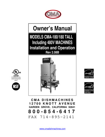
2. Getting Started2.1.Introduction to CMA-180The CMA-180 is a hot water sanitizing, single rack, door-type dishmachine. It is a stand-alonemachine featuring a self-contained booster heater (optional). The only external connectionsnecessary are power supply, water supply, drainpipe, and chemical dispensers. The machineutilizes recirculated wash water and fresh water final rinse. The CMA-180 can be converted bothas a straight through and corner with a door handle kit.Operation of the CMA-180 is automatic. To initially fill the machine daily, press “Auto Fill” rockerswitch. Auto Fill timer will fill the machine until water begins to flow into the scrap trap. When thedoor is opened and then closed, the wash cycle begins automatically. The wash tank heater willmaintain the wash water temperature at 155 F. The booster heater will produce a minimum of180 F final rinse water each cycle providing the incoming water supply is a minimum 120 F.This machine can be used as a Low Temp machine provided NSF Standard 29 ChemicalSanitizing Feeder (not supplied with machine) is installed.This manual is structured to provide a complete reference guide to the CMA-180. It is presentedin a manner that all users will be able to comprehend and use as an effective tool in supportingthe operation and maintenance of the dishmachine. The first section explains how the machine ispackaged and what to look for when receiving the machine.Instructions are provided in the manual explaining how to unpack the machine and then installand set up the machine for use. Requirements are given for plumbing, wiring, and spaceconsiderations. These attributes of the machine are always taken into consideration by our welltrained sales representatives prior to the order being placed. In the manual, additional installationguidance is given to ensure the machine can run at optimum conditions.The Operation Section of the manual may be used for instruction and procedures when required.We make this portion of the manual easy to understand so that all levels of operators may beable to read and comprehend the operation of the machine. The function of the machine itself ismostly automatic and takes little training to put into full operation. The Operation Section alsoincludes diagnostic considerations for the machine when problems occur.We are committed to providing the best machines and customer service in the foodindustry and your feedback is welcome.DISCLAIMERSCMA expressly disclaims any and all warranties, express or implied, relating to the installation of any and all CMA equipment that is installed by chemical dealers, contracted servicers or thirdparty servicers to CMA equipment. If the installation instructions are not followed exactly (to the letter), or, if any person or company conducting the installation of the CMA equipment, revise theinstallation procedures or alter the instructions in any manner, the CMA warranty becomes void. If, due to the improper installation of CMA equipment, this equipment ceases to operate properly oraffects other parts of the CMA dishwashing equipment, in that the other parts become defective, the CMA warranty becomes void. CMA will not be liable or responsible or warrant CMAequipment, due to improper installation of any CMA model dishwasher.CMA does NOT endorse “Tankless On-Demand” water heaters for use on CMA Dishmachine products. On most applications, thevolume of hot water required for commercial dishmachines exceeds the capacity of these types of heating sources. You will findthat most, if not all, commercial dishmachines have been programmed with auto-filling features that require quick filling, with adesignated limited time.CMA DOES endorse, and highly recommends, the standard “tank” style water heaters, sized properly to handle each particularfacility with their water heating requirements. A “tank” style water heater stores and supplies a large capacity of preheated waterbefore providing hot water to the dishmachine. To meet required health codes, there must be a reliable and consistent flow ofadequate hot water supplied to the dishmachine. If the facilities’ “tank” style water heater is marginal in size, CMA recommendsinstalling a proper size Hatco Booster Heater, a CMA’s E-Temp 40 or 70-degree-rise Booster Heater (that can be installed on CMAConveyors), or a CMA Temp-Sure Booster Heater (for door and undercounter dishmachines). All are designed to adequatelyachieve results.Warning: cancer and reproductive harm – www.P65Warnings.ca.govMODEL CMA-180 INSTALLATION & OPERATION Rev. 2.08BPage 4
2.2.Receiving and InstallationStep 1: Remove packaging material.Step 2: Remove service manual and machine legs from inside the wash tank.Step 3: Install legs into dishmachine leg lockets and adjust the feet. Set themachine in place. Level the machine side – to – side and front – to –back.Step 4: It is recommended that a distance of at least eight inches (8”) bebetween the table scrap sink and the dishmachine.2.2.1. Electrical*Prior to installation make sure the electrical supply is compatible with the specificationson the machines data plate.WARNING: Electrical and grounding connections must comply with the applicableportions of the National Electrical Code and/or other local electrical codes.Note: For supply connections, use copper wire only rated at 90 degree C minimum.The control panel provides a 1” conduit connection point on the rear of the panel. Referto Section 3 for wiring options.This machine is equipped to handle both single and three phase applications. SeeSection 1: Specifications 1.1 for the proper electrical ratings.2.2.2. Plumbing*Minimum 140 F / Minimum 180 F (if machine ordered without booster heater, watersupply ¾” – minimum 20 psi, 6 gpm flow rate and 60 gph recovery rate. Plumbingconnection located on the top of the machine.Notice to Plumber: The plumber connecting this machine is responsible for makingcertain that the water lines are THOROUGHLY FLUSHED OUT BEFORE connecting tothe dishwasher.CMA recommends utilizing a water softening system to maintain water hardnessmeasurements of 3.5 gpg (grains per gallon) or less. This will assure maximumresults and optimum operation of the dishmachine.Note: high iron levels in the water supply can cause staining and may require an ironfilter. High chlorine levels in the water supply can cause pitting and may require achloride removal system.If an inspection of the dishwasher or booster heater reveals lime buildup after theequipment has been in service, water treatment is recommended. If water softener isalready in place, ensure there is a sufficient level of salt.The drain is a two inch (2”) pipe sleeve attached by “No-Hub” plumbing connection at thebottom of the scrap trap. Account’s drain should be no higher than 11” to allow themachine to drain properly.*Electrical and plumbing connections must be made by qualified person who comply with allavailable Federal, State, and Local Health, Electrical, Plumbing and Safety codesMODEL CMA-180 INSTALLATION & OPERATION Rev. 2.08BPage 5
2.2.3. Chemical Dispensers*This machine must be operated with an automatic detergent feeder and, if applicable, anautomatic chemical sanitizer feeder, including a visual means to verify that detergents andsanitizers are delivered or a visual or audible alarm to signal if detergents and sanitizers are notavailable for delivery to the respective washing and sanitizing systems. Please see instructionsfor electrical and plumbing connections located in this manual and in the feeder equipmentmanual.1. Check valves should be installed directly at the mixing chamber coupling located by thevacuum breaker on the back of machine. There are two 1/8” FPT mounting holesprovided on the mixing chamber coupling, which will position the check valves parallel tothe machine avoiding any chemicals from dripping onto the stainless steel should a leakdevelop. One hole is for rinse chemical and one for sanitizer chemical, but only one isneeded with the High Temp machines — for rinse chemical only.2. Remove the plugs from the mixing chamber; and install injection fittings (supplied withyour dispenser).3. A 7/8” detergent injection hole is provided in the back of the wash tank. Remove the S.S.plug and install the detergent fitting (supplied with your dispenser).4. A 7/8” chemical probe hole is provided in the front of the wash tank heater just below hilimit switch. Insert the probe into the hole from inside the wash tank and secure it with theprobe retaining nut provided.2.2.3.1.Low Temperature ApplicationsSee dispenser manufacturing operational instructions for sanitizer adjustments for LowTemp applications.The sanitizing pump operates when the fresh water enters the machine during final rinse.The water is treated at 50 PPM (parts per million). The pressure regulator is adjusted to20 PSI. This allows 0.82 gallons of water to enter the machine each time a rack iswashed.It is recommended that the 5-1/4% chemical solution be standardized to allow uniformdispensing of the sanitizing solution into the flow of rinse water as the machine operates.At this level, maximum shelf life is available.Note: Use only commercial-grade detergents and rinse aids recommended by yourchemical professional. Do not use detergents and rinse aids formulated for residentialdishwashers.Low Temperatures chemical-sanitizing dishmachines must not exceed 6% sodiumhypochlorite solution (bleach) as the sanitizing agent. Higher levels may damagestainless or components.Follow the directions precisely that are on the litmus paper vial and test the water on thesurface of the bottom of the glasses.*Electrical and plumbing connections must be made by qualified person who comply with allavailable Federal, State, and Local Health, Electrical, Plumbing and Safety codesMODEL CMA-180 INSTALLATION & OPERATION Rev. 2.08BPage 6
2.2.4. Exhaust Fan Control Kit p/n 17528.00 Instructions1. Connect terminal #1 on timer block (Red) to heater contactor terminal marked L32. Connect terminal #3 on timer block (Blue) to heater contactor terminal marked L13. Connect terminal #2 on timer block (Red/Black) to fan contactor coil terminal.4. Connect terminal #3 on timer block (Blue) to other fan contactor coil terminal5. Connect terminal # 3 on timer block (Blue) to sixth cam top terminal on timer assembly.6. Connect terminal #6 on timer block (Blue) to sixth cam middle terminal on timerassembly.7. Connect power source of 220 Vac or 110 Vac to L1 and L2 (N) on fan control contactor.8. Connect exhaust fan motor to T1 and T2 on other side of fan control contactor.MODEL CMA-180 INSTALLATION & OPERATION Rev. 2.08BPage 7
2.2.5.Water Tempering Kit (Optional)MODEL CMA-180 INSTALLATION & OPERATION Rev. 2.08BPage 8
2.2.6. Installation ChecklistDishmachine checked for concealed damage.Hot water supply is 140 (60 C)Incoming water supply line is ¾”.Incoming water supply is 6 gpm minimum capable at 20 psi flow pressure.Machine circuit breaker is properly sized.Service voltage and phase type are correct to machine data plate.High leg of voltage is connected to L2 (three-phase).Dishmachine is properly ventilated.Floor drain plumbing is installed with air gap. MUST MEET LOCAL CODES.Dishmachine is properly grounded.Dishmachine is properly leveled.Dishrack guides are adjusted to level of dishtable.Machine circuit breaker is labeled D/W2.2.7. Machine Start-Up Procedures for High Temp machines1. Place the scrap baskets over the wash tanks.2. Secure the wash & rinse arms and check the free-spin.3. Open the control panel and select ‘normal” toggle switch position.4. Adjust the rinse pressure to 20 PSI flow pressure using the regulator and the gaugeprovided on machine.a. Turn the power switch to the “Off” position.b. Close doors and press “Auto Fill” rocker switch;the water overflows into the scraptrap.c.Turn the power switch to “on” position. SEE NOTE FOR BOOSTER HEATERBELOW.d. While holding “flush” toggle switch, to activate the water solenoid, adjust thepressure regulator until the gauge reads 20 PSI. NOTE: Booster heater is filledduring this procedure.5. Connect the detergent and rinse dispenser to the power block supplied & labeled insidethe control panel (208-220) volt.6. Remove the plug from the mixing chamber and install the rinse injection fitting.7. A 7/8” chemical probe hole is provided in the wash tank behind wash tank heater cover.8. A 7/8” detergent fitting hole is provided in the wash tank behind the machine.9. Check the machine operating temperatures. Adjust if necessary.MODEL CMA-180 INSTALLATION & OPERATION Rev. 2.08BPage 9
a. After the machine has warmed up for five to ten minutes (5 – 10 min.), observethe wash and rinse temperatures. The wash temperature must be 155 Fminimum. The rinse temperature must be 180 F minimum. If necessary, adjustthe temperatures by removing the panel in front of the respective heater andturning the adjustment stem clockwise to increase.NOTE: Rinse water temperature must be observed during the rinse cycle.10. Check all water and drain fittings for leaks.11. Install the wall chart and instruct the machine operator on the proper cleaning andoperation of the CMA-180.Caution: Booster HeaterBooster heater is shipped on the dishmachine empty to prevent freezing. When themachineis powered up for the first time, the booster heater must be filled immediatelyto prevent damage to the heating element. See Section 2.2.7 (4d.)To prevent booster heater element damage, CMA has removed a wire from the high limitswitch. When initially filling of a newly installed dishmachine, you must fill the boostertank prior to connecting the removed wire. When water is observed entering the wash tankthis indicates the booster tank is full and removed wire can be connected. Failure to followthese important instructions will destroy the heating element because of dry -firing.2.2.8. Daily Cleaning Procedures1. Remove scrap screens from top of the booster tank.2. Clean/Remove debris from around the float switch.3. Check for foreign objects like utensils stuck underneath heater element or wedgedadjacent to perforated guard.4. Check that float switch moves freely up and down.5. Reinstall scrap screens and cycle to flush.MODEL CMA-180 INSTALLATION & OPERATION Rev. 2.08BPage 10
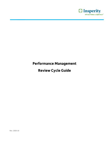
2.2.9.Electrical RequirementsThe CMA-180 comes standard factory, wired for 3-phase operation. Check the electrical dataplate to confirm this. Refer to “Electrical Requirements” Figure 1-A, for proper wiring instructionfor both rectangular booster and wash heaters conversion. Also check the wiring diagram toproperly wire the terminal power block, tank heater, and booster heater for 1 phase (or 1Bdiagram below). Refer to Figure 1-B, for proper wiring instruction for both triangular booster andwash heaters conversion.SINGLE PHASE POWERNOTE: See “Wiring options” section for 1-phase power supply.Figure 1-AFigure 1-BMODEL CMA-180 INSTALLATION & OPERATION Rev. 2.08BPage 11
3. Wiring Options3-Phase and 1 PhaseWiring OptionsSingle-Source240V 3-Phase(Without booster)Single-Source240V 3-PhaseStandardSingle-Source240V 1-PhaseTwo-Source240V 1-PhaseSingle-Source240V 1-Phase(Without booster)DISPENSER HOOK-UP1. The power signal is 208/230 volts. The power block is labeled inside the control box.Conduit holes for both detergent & rinse are supplied on the control box.2. A threaded (1/8”) injection point is provided on the final rinse Teflon mixing chamberlocated off the back of the machine.3. A (7/8”) hole is provided in the tank for a probe access. It is located on the front side ofthe wash tank inside the heater cover.MAIN POWER CONNECTIONPlease refer to the machine data plate or choose one of the five (5) power connections illustratedabove. Electrical requirements are shown for machines with or without booster heater, three orsingle phase.WARNING: Insure that the machine is properly grounded and complies with all local and nationalcodes. Injury or death may occur from shock, if the machine is not properly grounded.Install power supply wires, L1, L2 and L3 (3-Phase) to the appropriate terminals marked L1, L2,and L3 on the power block. (If applicable, the high or “wild” leg must be connected to the L2Terminal.)MODEL CMA-180 INSTALLATION & OPERATION Rev. 2.08BPage 12
4. Quick service guideMODEL: CMA 180 HIGH TEMPTECHNICAL ISSUEDoor magnetic reed switch problemDoor mechanical switch problemPump motor not runningPump motor runs continuousCAUSEFaulty magnetic reed switchSOLUTIONCheck wire connections inside control boxSwitch alignment issueContact factory for new retrofit, corner P/N 00566.10straight P/N 00566.20Align switchSwitch button brokeReplace switch, P/N00562.00Delimer switch is in OFF positionFlip to NORMAL positionLoose wire connectionsCheck and crimp connectorsFaulty # 3 micro switch in cam timerReplace micro switch, P/N 00411.00Faulty contactorReplace contactor, P/N 00404.85Faulty wash pump motorReplace wash pump motor, P/N 00201.00Faulty # 3 micro switch in cam timerReplace micro switch, P/N 00411.00Delimer switch is in DELIME positionFlip to NORMAL positionFaulty contactorReplace contactor, P/N 00404.85Booster heater thermostat not properly setAdjust thermostatIncoming main water temperature below 140 F Raise water temperature to 140 FFinal rinse water below 180 degree FWash tank heater is not operationalTripped or faulty high limit switchReset or replace high limit switch, P/N 17523.51Faulty contactorReplace contactor, P/N 13003.17Faulty booster heater elementReplace heating element, P/N 13417.67Scaled heating elementThermostat is not properly adjustedDe- scale heating elementAdjust thermostatLoose lead connectionTripped or faulty high limit switchCheck connectors and secureReset or replace high limit switch, P/N 17523.51Faulty float switchReplace float switch, P/N 13463.00Faulty contactorReplace contactor, P/N13003.50Faulty heating elementReplace heating element, P/N 13417.65Water regulator not adjusted properlyClogged final rinse spray jetsLow water pressure at the final rinse Missing final rinse spray end capWater solenoid leaksIncrease pressureLow incoming water pressure from buildingScaled or dirty solenoid valveClean valveFaulty solenoid valve diaphragmThermostat not properly setReplace diaphragm, P/N 00706.00Adjust thermostatWash water temperature too low/high Scaled heating elementMachine does not operate when thedoor is closedAdjust regulator to 18-20 PSIClean jetsReplace end cap, P/N 00308.17Clean scale, delime machineFaulty temperature gaugePosition or proper operation of door switchReplace gauge, P/N 03202.00Adjust or replace door switch, P/N 00557.55Delimer switch is on OFF positionFaulty 1st micro switch in cam timerFlip to NORMAL positionReplace micro switch, P/N 00411.00Check cam timer motorReplace timer if needed, P/N 00409.17Check ice cube relayReplace if faulty, P/N 00631.05Replace contactor, P/N 00404.85Faulty wash pump contactorMODEL CMA-180 INSTALLATION & OPERATION Rev. 2.08BPage 13
5. INITIAL PARTS KIT P/N SCRIPTIONCMA-180 Drain Stopper O RingPump Assy 110/220V 60 Hz (Open)Pump Seal KitCMA-180 Buna Gasket (#302.17)CMA-180 Wash Spray ArmCMA-180 Rinse Arm W/BearingCMA-180 Rinse Arm SS End PlugSpray Arm End Plug SSSpray Base Lock PinContactor 208.240V 20AMPStart/Fill Switch ToggleMicro SwitchCMA-180 Illuminated PlugCMA-180 Power SwitchToggle Switch DPDT 15 AMP/DelimerTimer Motor Assy 60 Sec. 220V/60HzRoller Door SwitchDoor SpringIce Cube Relay 220V¾ Water Solenoid Repair Kit JE¾ Vac Breaker Rep Kit Watts¾ Solenoid Coil JE 220VThermometer CMA-180 “Wash”Thermometer CMA-180 “Rinse”Counter (Face Mount Sm) 220/50Contactor 60 AMP 3 PoleContactor 30 AMPSS Final Rinse Spray Jet – HTEGO Thermostat Retrofit Kit RinseCMA-180 Booster Heater GasketImmersion Heater 12 Kw 3PH/1PH, 240VThermostat Heater CMA-44/CMA-180 WashLiquid Level Switch SS – CMA-44Pressure GaugeImmersion Heater 6 Kw 3hp/1ph, 240VHi Limit Switch 250 degNO. REQ’D111111111111111111111111111111111111NOTE: CMA recommend that this Model CMA-180 initial parts kit bekept on hand, as a back up supply, in the event your machine shouldrequire emergency service. All the parts included in this kit areunique to the CMA-180 dishmachine, and are essential to the “quality”operation and customer service to the CMA-180 unit.MODEL CMA-180 INSTALLATION & OPERATION Rev. 2.08BPage 14
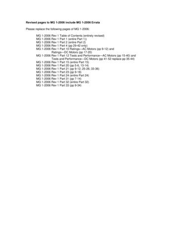
6. Auto-Fill Solid State TimerPre-selected delay period can be adjusted byturning dip switches on for proper time setting.Removal of input power will reset the control.AUTO-FILLSWITCHvioletvioletL2L1WASH L CMA-180 INSTALLATION & OPERATION Rev. 2.08BorangebluePage 15
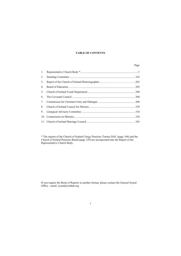
7. Wire Diagram for CMA-180 With Booster HeaterMODEL CMA-180 INSTALLATION & OPERATION Rev. 2.08BPage 16
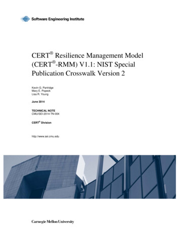
NSE SIGNAL {BOOSTERHEATERCONTACTORL2GROUNDWASH PUMPCONTACTOR8. Wire Diagram for CMA-180 Booster OnlyT2T1T3T2T1T3T2T1PUMPMOTORHI LIMITSWITCH5kWADJ.THERMOSTATWASH TANKHEATER12kWBOOSTERHEATERMODEL CMA-180 INSTALLATION & OPERATION Rev. 2.08BPage 17
9. Wire Diagram for CMA-180 Without Booster HeaterMODEL CMA-180 INSTALLATION & OPERATION Rev. 2.08BPage 18
10. Wire Diagram for 480V 180 Without Booster HeaterMODEL CMA-180 INSTALLATION & OPERATION Rev. 2.08BPage 19
11. Wire Diagram for 480V 180 With Booster HeaterMODEL CMA-180 INSTALLATION & OPERATION Rev. 2.08BPage 20
CMA DOES endorse, and highly recommends, the standard "tank" style water heaters, sized properly to handle each particular facility with their water heating requirements. A "tank" style water heater stores and supplies a large capacity of preheated water . Account's drain should be no higher than 11" to allow the machine to drain .