Transcription
SD67HYDRAULICSPIKE DRIVERUSER MANUALSafety, Operation and Maintenance 2014 Stanley Black & Decker, Inc.New Britain, CT 06053U.S.A.17488 1/2015 Ver. 8
2 SD67 User Manual
TABLE OF CONTENTSSAFETY SYMBOLS.4SAFETY PRECAUTIONS.5TOOL STICKERS & TAGS.6HOSE TYPES.7HOSE RECOMMENDATIONS.8FIGURE 1. TYPICAL HOSE CONNECTIONS.8HTMA REQUIREMENTS.9OPERATION.10TOOL PROTECTION & CARE. 11TROUBLESHOOTING.12FIGURE 2. CHARGING THE ACCUMULATOR.13CHARGING THE AL TOOLS.14SD67 PARTS ILLUSTRATION.15SD67 PARTS LIST.16IMPORTANTTo fill out a Product Warranty Validation form, and for information on your warranty,visit Stanleyhydraulics.com and select the Company tab, Warranty.(NOTE: The warranty Validation record must be submitted to validate the warranty).SERVICING: This manual contains safety, operation, and routine maintenance instructions. Stanley Hydraulic Toolsrecommends that servicing of hydraulic tools, other than routine maintenance, must be performed by an authorizedand certified dealer. Please read the following warning.WARNINGSERIOUS INJURY OR DEATH COULD RESULT FROM THE IMPROPER REPAIR OR SERVICE OF THISTOOL.REPAIRS AND / OR SERVICE TO THIS TOOL MUST ONLY BE DONE BY AN AUTHORIZED ANDCERTIFIED DEALER.For the nearest authorized and certified dealer, call Stanley Hydraulic Tools at the number listed on the back of thismanual and ask for a Customer Service Representative.SD67 User Manual 3
SAFETY SYMBOLSSafety symbols and signal words, as shown below, are used to emphasize all operator, maintenance and repair actions which, if not strictly followed, could result in a life-threatening situation, bodily injury or damage to equipment.This is the safety alert symbol. It is used to alert you to potential personal injuryhazards. Obey all safety messages that follow this symbol to avoid possibleinjury or death.DANGERThis safety alert and signal word indicate an imminently hazardous situationwhich, if not avoided, will result in death or serious injury.WARNINGThis safety alert and signal word indicate a potentially hazardous situationwhich, if not avoided, could result in death or serious injury.CAUTIONThis safety alert and signal word indicate a potentially hazardous situationwhich, if not avoided, could result in death or serious injury.CAUTIONThis signal word indicates a potentially hazardous situation which, if not avoided, may result in property damage.NOTICEThis signal word indicates a situation which, if not avoided, will result in damageto the equipment.IMPORTANTThis signal word indicates a situation which, if not avoided, may result in damage to the equipment.Always observe safety symbols. They are included for your safety and for the protection of the tool.LOCAL SAFETY REGULATIONSEnter any local safety regulations here. Keep these instructions in an area accessible to the operator and maintenance personnel.4 SD67 User Manual
SAFETY PRECAUTIONSTool operators and maintenance personnel must alwayscomply with the safety precautions given in this manualand on the stickers and tags attached to the tool andhose. Do not operate the tool at oil temperatures above140 F/60 C. Operation at higher temperatures cancause higher than normal temperatures at the toolwhich can result in operator discomfort.These safety precautions are given for your safety. Review them carefully before operating the tool and beforeperforming general maintenance or repairs. Do not operate a damaged, improperly adjusted, orincompletely assembled spike driver. Do not weld, cut with an acetylene torch, or hardfacethe spike driver ram or foot. To avoid personal injury or equipment damage, alltool repair, maintenance and service must only beperformed by authorized and properly trained personnel.Supervising personnel should develop additional precautions relating to the specific work area and localsafety regulations. If so, place the added precautions inthe space provided in this manual.The SD67 Hydraulic Spike Driver will provide safe anddependable service if operated in accordance with theinstructions given in this manual. Read and understandthis manual and any stickers and tags attached to thetool and hoses before operation. Failure to do so couldresult in personal injury or equipment damage. Operator must start in a work area without bystanders. The operator must be familiar with all prohib itedwork areas such as excessive slopes and dangerous terrain conditions. Establish a training program for all operators to ensure safe operation. Do not operate the tool unless thoroughly trained orunder the supervision of an instructor. Always wear safety equipment such as goggles, earand head protection, and safety shoes at all timeswhen operating the tool. Do not inspect or clean the tool while the hydraulicpower source is connected. Accidental engagementof the tool can cause serious injury. Always connect hoses to the tool hose couplers before energizing the hydraulic power source. Be sureall hose connections are tight.SD67 User Manual 5
TOOL STICKERS & TAGS25610Railroad Help Desk Sticker73189SD67 Name Tag14090Stanley LogoNOTE:THE INFORMATION LISTEDON THE STICKERS SHOWN,MUST BE LEGIBLE AT ALLTIMES.REPLACE DECALS IFTHEY BECOME WORN ORDAMAGED. REPLACEMENTSARE AVAILABLE FROMYOUR LOCAL STANLEYDISTRIBUTOR.The safety tag (P/N 15875) at right isattached to the tool when shipped fromthe factory. Read and understand thesafety instructions listed on this tag beforeremoval. We suggest you retain this tag andattach it to the tool when not in use.D A N G E R1.FAILURE TO USE HYDRAULIC HOSE LABELED AND CERTIFIED AS NON-CONDUCTIVE WHEN USING HYDRAULICTOOLS ON OR NEAR ELECTRICAL LINES MAY RESULT INDEATH OR SERIOUS INJURY.BEFORE USING HOSE LABELED AND CERTIFIED AS NONCONDUCTIVE ON OR NEAR ELECTRIC LINES BE SURE THEHOSE IS MAINTAINED AS NON-CONDUCTIVE. THE HOSESHOULD BE REGULARLY TESTED FOR ELECTRIC CURRENT LEAKAGE IN ACCORDANCE WITH YOUR SAFETYDEPARTMENT INSTRUCTIONS.2.A HYDRAULIC LEAK OR BURST MAY CAUSE OIL INJECTION INTO THE BODY OR CAUSE OTHER SEVEREPERSONAL INJURY.A.DO NOT EXCEED SPECIFIED FLOW AND PRESSUREFOR THIS TOOL. EXCESS FLOW OR PRESSURE MAYCAUSE A LEAK OR BURST.B.DO NOT EXCEED RATED WORKING PRESSURE OFHYDRAULIC HOSE USED WITH THIS TOOL. EXCESSPRESSURE MAY CAUSE A LEAK OR BURST.C.CHECK TOOL HOSE COUPLERS AND CONNECTORSDAILY FOR LEAKS. DO NOT FEEL FOR LEAKS WITHYOUR HANDS. CONTACT WITH A LEAK MAY RESULTIN SEVERE PERSONAL INJURY.D A N G E RD.DO NOT LIFT OR CARRY TOOL BY THE HOSES. DONOT ABUSE HOSE. DO NOT USE KINKED, TORN ORDAMAGED HOSE.3.MAKE SURE HYDRAULIC HOSES ARE PROPERLY CONNECTED TO THE TOOL BEFORE PRESSURING SYSTEM.SYSTEM PRESSURE HOSE MUST ALWAYS BE CONNECTED TO TOOL “IN” PORT. SYSTEM RETURN HOSEMUST ALWAYS BE CONNECTED TO TOOL “OUT” PORT.REVERSING CONNECTIONS MAY CAUSE REVERSETOOL OPERATION WHICH CAN RESULT IN SEVEREPERSONAL INJURY.4.DO NOT CONNECT OPEN-CENTER TOOLS TO CLOSEDCENTER HYDRAULIC SYSTEMS. THIS MAY RESULT INLOSS OF OTHER HYDRAULIC FUNCTIONS POWERED BYTHE SAME SYSTEM AND/OR SEVERE PERSONAL INJURY.5.BYSTANDERS MAY BE INJURED IN YOUR WORK AREA.KEEP BYSTANDERS CLEAR OF YOUR WORK AREA.6.WEAR HEARING, EYE, FOOT, HAND AND HEAD PROTECTION.7.TO AVOID PERSONAL INJURY OR EQUIPMENT DAMAGE,ALL TOOL REPAIR MAINTENANCE AND SERVICE MUSTONLY BE PERFORMED BY AUTHORIZED AND PROPERLYTRAINED PERSONNEL.I M P O R T A N TI M P O R T A N TREAD OPERATION MANUAL ANDSAFETY INSTRUCTIONS FOR THISTOOL BEFORE USING IT.READ OPERATION MANUAL ANDSAFETY INSTRUCTIONS FOR THISTOOL BEFORE USING IT.USE ONLY PARTS AND REPAIRPROCEDURES APPROVED BYSTANLEY AND DESCRIBED IN THEOPERATION MANUAL.USE ONLY PARTS AND REPAIRPROCEDURES APPROVED BYSTANLEY AND DESCRIBED IN THEOPERATION MANUAL.TAG TO BE REMOVED ONLY BYTOOL OPERATOR.TAG TO BE REMOVED ONLY BYTOOL OPERATOR.SEE OTHER SIDESEE OTHER SIDESAFETY TAG P/N 15875 (Shown smaller then actual size)6 SD67 User Manual
HOSE TYPESThe rated working pressure of the hydraulic hose must be equal to or higher than the relief valve setting on the hydraulic system. There are three types of hydraulic hose that meet this requirement and are authorized for use withStanley Hydraulic Tools. They are:Certified non-conductive — constructed of thermoplastic or synthetic rubber inner tube, synthetic fiber braidreinforcement, and weather resistant thermoplastic or synthetic rubber cover. Hose labeled certified nonconductive is the only hose authorized for use near electrical conductors.Wire-braided (conductive) — constructed of synthetic rubber inner tube, single or double wire braid reinforcement, and weather resistant synthetic rubber cover. This hose is conductive and must never be used nearelectrical conductors.Fabric-braided (not certified or labeled non-conductive) — constructed of thermoplastic or synthetic rubber inner tube, synthetic fiber braid reinforcement, and weather resistant thermoplastic or synthetic rubber cover. Thishose is not certified non-conductive and must never be used near electrical conductors.HOSE SAFETY TAGSTo help ensure your safety, the following DANGER tags are attached to all hose purchased from Stanley HydraulicTools. DO NOT REMOVE THESE TAGS.If the information on a tag is illegible because of wear or damage, replace the tag immediately. A new tag may beobtained from your Stanley Distributor.D A N G E RD A N G E R1.FAILURE TO USE HYDRAULIC HOSE LABELED AND CERTIFIED AS NON-CONDUCTIVEWHEN USING HYDRAULIC TOOLS ON OR NEAR ELECTRIC LINES MAY RESULT INDEATH OR SERIOUS INJURY.FOR PROPER AND SAFE OPERATION MAKE SURE THAT YOU HAVE BEEN PROPERLY TRAINED IN CORRECT PROCEDURES REQUIRED FOR WORK ON OR AROUNDELECTRIC LINES.2.BEFORE USING HYDRAULIC HOSE LABELED AND CERTIFIED AS NON-CONDUCTIVEON OR NEAR ELECTRIC LINES. WIPE THE ENTIRE LENGTH OF THE HOSE AND FITTING WITH A CLEAN DRY ABSORBENT CLOTH TO REMOVE DIRT AND MOISTURE ANDTEST HOSE FOR MAXIMUM ALLOWABLE CURRENT LEAKAGE IN ACCORDANCE WITHSAFETY DEPARTMENT INSTRUCTIONS.3.DO NOT EXCEED HOSE WORKING PRESSURE OR ABUSE HOSE. IMPROPER USEOR HANDLING OF HOSE COULD RESULT IN BURST OR OTHER HOSE FAILURE.KEEP HOSE AS FAR AWAY AS POSSIBLE FROM BODY AND DO NOT PERMIT DIRECTCONTACT DURING USE. CONTACT AT THE BURST CAN CAUSE BODILY INJECTIONAND SEVERE PERSONAL INJURY.4.HANDLE AND ROUTE HOSE CAREFULLY TO AVOID KINKING, ABRASION, CUTTING, ORCONTACT WITH HIGH TEMPERATURE SURFACES. DO NOT USE IF KINKED. DO NOTUSE HOSE TO PULL OR LIFT TOOLS, POWER UNITS, ETC.5.CHECK ENTIRE HOSE FOR CUTS CRACKS LEAKS ABRASIONS, BULGES, OR DAMAGE TO COUPLINGS IF ANY OF THESE CONDITIONS EXIST, REPLACE THE HOSEIMMEDIATELY. NEVER USE TAPE OR ANY DEVICE TO ATTEMPT TO MEND THE HOSE.6.AFTER EACH USE STORE IN A CLEAN DRY AREA.SEE OTHER SIDESIDE 1SEE OTHER SIDE(Shown smaller than actual size)DO NOT REMOVE THIS TAGDO NOT REMOVE THIS TAGTHE TAG SHOWN BELOW IS ATTACHED TO “CERTIFIED NON-CONDUCTIVE” HOSESIDE 2D A N G E RD A N G E R1.DO NOT USE THIS HYDRAULIC HOSE ON OR NEAR ELECTRIC LINES. THIS HOSE ISNOT LABELED OR CERTIFIED AS NON-CONDUCTIVE. USING THIS HOSE ON OR NEARELECTRICAL LINES MAY RESULT IN DEATH OR SERIOUS INJURY.5.CHECK ENTIRE HOSE FOR CUTS CRACKS LEAKS ABRASIONS, BULGES, OR DAMAGE TOCOUPLINGS IF ANY OF THESE CONDITIONS EXIST, REPLACE THE HOSE IMMEDIATELY.NEVER USE TAPE OR ANY DEVICE TO ATTEMPT TO MEND THE HOSE.2.FOR PROPER AND SAFE OPERATION MAKE SURE THAT YOU HAVE BEEN PROPERLYTRAINED IN CORRECT PROCEDURES REQUIRED FOR WORK ON OR AROUND ELECTRIC LINES.6.AFTER EACH USE STORE IN A CLEAN DRY AREA.3.DO NOT EXCEED HOSE WORKING PRESSURE OR ABUSE HOSE. IMPROPER USE ORHANDLING OF HOSE COULD RESULT IN BURST OR OTHER HOSE FAILURE. KEEP HOSEAS FAR AWAY AS POSSIBLE FROM BODY AND DO NOT PERMIT DIRECT CONTACTDURING USE. CONTACT AT THE BURST CAN CAUSE BODILY INJECTION AND SEVEREPERSONAL INJURY.4.HANDLE AND ROUTE HOSE CAREFULLY TO AVOID KINKING, CUTTING, OR CONTACTWITH HIGH TEMPERATURE SURFACES. DO NOT USE IF KINKED. DO NOT USE HOSE TOPULL OR LIFT TOOLS, POWER UNITS, ETC.DO NOT REMOVE THIS TAGDO NOT REMOVE THIS TAGTHE TAG SHOWN BELOW IS ATTACHED TO “CONDUCTIVE” HOSE.SEE OTHER SIDESEE OTHER SIDESIDE 1SIDE 2(Shown smaller than actual size)SD67 User Manual 7
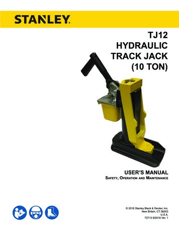
8 SD67 User ManualAll hydraulic hose must meet or exceedspecifications as set forth by SAE J517.All hydraulic hose must have at least a ratedminimum working pressure equal to the maximum hydraulic system relief valve setting.This chart is intended to be used for hydraulictool applications only based on Stanley Hydraulic Tools tool operating requirements andshould not be used for any other applications.The chart to the right shows recommendedminimum hose diameters for various hoselengths based on gallons per minute (gpm)/liters per minute (lpm). These recommendations are intended to keep return line pressure(back pressure) to a minimum acceptable level to ensure maximum tool performance.Tool to Hydraulic Circuit HoseRecommendations15-34MMInside DiameterINCHUSE(Press/Return)PSIup to 10up to 33/810Both225049-6013-16FLOW RETURN FLOWPRESSURE26-100up to 25100-20051-100up to 50100-30051-100up to 5026-100up to 258-30up to 830-6015-30up to 1530-9015-30up to 157.5-30up to 7.5Figure 1. Typical Hose 75175175175175175155BARMin. Working PressureCertified Non-Conductive Hose - Fiber Braid - for Utility Bucket TrucksMETERSHose LengthsFEETConductive Hose - Wire Braid or Fiber Braid -DO NOT USE NEAR ELECTRICAL CONDUCTORS4-64-9LPMOil FlowGPMHOSE RECOMMENDATIONS
HTMA / EHTMA REQUIREMENTSHTMA / EHTMA REQUIREMENTSHTMAHYDRAULIC SYSTEM REQUIREMENTSTYPE INominal Operating Pressure(at the power supply outlet)4-6 gpm(15-23 lpm)1500 psi(103 bar)TOOL TYPETYPE IITYPE RR7-9 gpm(26-34 lpm)1500 psi(103 bar)9-10.5 gpm(34-40 lpm)1500 psi(103 bar)System relief valve setting(at the power supply outlet)2100-2250 psi(145-155 bar)2100-2250 psi(145-155 bar)2200-2300 psi(152-159 bar)2100-2250 psi(145-155 bar)Maximum back pressure(at tool end of the return hose)250 psi(17 bar)250 psi(17 bar)250 psi(17 bar)250 psi(17 bar)Measured at a max. fluid viscosity of:(at min. operating temperature)400 ssu*400 ssu*400 ssu*400 ssu*(82 centistokes) (82 centistokes) (82 centistokes) (82 centistokes)Temperature: Sufficient heat rejectioncapacity to limit max. fluid temperature to:(at max. expected ambient temperature)140 F(60 C)Flow Range140 F(60 C)140 F(60 C)TYPE III11-13 gpm(42-49 lpm)1500 psi(103 bar)140 F(60 C)3 hp5 hp6 hp7 hpMin. cooling capacity at a temperature(2.24 kW)(3.73 kW)(5.22 kW)(4.47 kW)difference of between ambient and fluid40 F40 F40 F40 Ftemps(22 C)(22 C)(22 C)(22 C)NOTE:Do not operate the tool at oil temperatures above 140 F (60 C). Operation at higher temperatures can cause operatordiscomfort at the tool.FilterMin. full-flow filtrationSized for flow of at least:(For cold temp. startup and max.dirt-holding capacity)25 microns30 gpm(114 lpm)Hydraulic fluid Petroleum based(premium grade, anti-wear, non-conductive)Viscosity (at min. and max. operating temps)100-400 ssu*25 microns30 gpm(114 lpm)25 microns30 gpm(114 lpm)100-400 ssu*100-400 ssu*(20-82 centistokes)25 microns30 gpm(114 lpm)100-400 ssu*NOTE:When choosing hydraulic fluid, the expected oil temperature extremes that will be experienced in service determine themost suitable temperature viscosity characteristics. Hydraulic fluids with a viscosity index over 140 will meet the requirementsover a wide range of operating temperatures.*SSU Saybolt Seconds UniversalEHTMAHYDRAULIC SYSTEMREQUIREMENTSCLASSIFICATIONBCDNominal Operating Pressure(at the power supply outlet)3.5-4.3 gpm(13.5-16.5 lpm)1870 psi(129 bar)4.7-5.8 gpm(18-22 lpm)1500 psi(103 bar)7.1-8.7 gpm(27-33 lpm)1500 psi(103 bar)9.5-11.6 gpm(36-44 lpm)1500 psi(103 bar)11.8-14.5 gpm(45-55 lpm)1500 psi(103 bar)System relief valve setting(at the power supply outlet)2495 psi(172 bar)2000 psi(138 bar)2000 psi(138 bar)2000 psi(138 bar)2000 psi(138 bar)Flow RangeNOTE: These are general hydraulic system requirements. See tool specification page for tool specific requirementsSD67 User Manual 9
OPERATIONPRE-OPERATION PROCEDURESPREPARATION FOR INITIAL USEEach unit as shipped has no special unpacking or assembly requirements prior to usage. Inspection to assure the unit was not damaged in shipping and does notcontain packing debris is all that is required.NOTE:The pressure increase in uncoupled hoses left in thesun may result in making them difficult to connect.When possible, connect the free ends of operatinghoses together.OPERATING PROCEDURESCHECK HYDRAULIC POWER SOURCE1. Observe all safety precautions.1. Using a calibrated flowmeter and pressure gauge,check that the hydraulic power source develops aflow of 7–10 gpm/26–38 lpm at 2000 psi/105–140bar.2. Move the hydraulic circuit control valve to the ONposition.3. Place the spike driver foot firmly on the spike to bedriven.2. Make certain the hydraulic power source is equippedwith a relief valve set to open at 2100–2250 psi/145–155 bar minimum.4. Squeeze the trigger to start the spike driver. Adequate down pressure is very important. When thespike fully sets in the tie, release the trigger.3. Check that the hydraulic circuit matches the tool foropen-center (OC) operation.NOTE:CHECK TOOL1. Make sure all tool accessories are correctly installed. Failure to install tool accessories prop erlycan result in damage to the tool or personal injury.2. There should be no signs of leaks.3. The tool should be clean, with all fittings and fasteners tight.CHECK TRIGGER MECHANISM1. Check that the trigger operates smoothly and is freeto travel between the ON and OFF positions.CONNECT HOSES1. Wipe all hose couplers with a clean lint-free clothbefore making connections.2. Connect the hoses from the hydraulic power sourceto the hose couplers on the spike driver. It is a goodpractice to connect the return hose first and disconnect it last to minimize or avoid trapped pressurewithin the spike driver.3. Observe flow indicators stamped on hose couplersto be sure that oil will flow in the proper direction.The female coupler is the inlet coupler.10 SD67 User ManualPartially depressing the trigger allows the tool tooperate at a slow speed, making it easy to start thespike in the tie.COLD WEATHER OPERATIONIf the spike driver is to be used during cold weather, preheat the hydraulic fluid at low engine speed. When using the normally recommended fluids, fluid temperatureshould be at or above 50 F/10 C (400 ssu/82 centistokes) before use.
TOOL PROTECTION & CARENOTICEIn addition to the Safety Precautions found inthis manual, observe the following for equipmentprotection and care. Always store an idle tool in a clean dry space, safefrom damage or pilferage. Do not exceed the rated limits or use the tool for applications beyond its design capacity. Always keep critical tool markings, such as labelsand warning stickers legible. Always replace hoses, couplings and other partswith replacement parts recommended by StanleyHydraulic Tools. Supply hoses must have a minimum working pressure rating of 2500 psi/175 bar. Permit only experienced personnel to perform toolrepair. Be sure to wipe all couplers clean before con necting.Use only lint-free cloths. The hydraulic circuit control valve must be in theOFF position when coupling or uncoupling thegrinder. Failure to do so may result in damage tothe quick couplers and cause overheating of the hydraulic system. Check fastener tightness often and before each usedaily.SD67 User Manual 11
TROUBLESHOOTINGIf symptoms of poor performance develop, the following chart can be used as a guide to correct the problem.When diagnosing faults in operation of the spike driver, always check that the hydraulic power source is supplyingthe correct hydraulic flow and pressure to the spike driver as listed in the table. Use a flowmeter known to be accurate. Check the flow with the hydraulic oil temperature at least 80 F/27 C.ProblemSpike driver does not run.Spike driver does not hiteffectively.CauseSolutionPower unit not functioning.Check power unit for proper flow andpressure (7–10 gpm I 26–38 lpm,2000 psi I 140 bar).Couplers or hoses blocked.Remove restriction.Pressure and return line hosesreversed at ports.Be sure hoses are connected to theirproper ports.Mechanical failure of piston orautomatic valve.Have inspected and repaired byauthorized dealer.Power unit not functioning.Check power unit for proper flow andpressure (7–10 gpm I 26–38 lpm,2000 psi I 140 bar).Couplers or hose blocked.Remove restriction.Low accumulator charge (pressurehose will pulse more than normal).Have recharge by authorized dealer.Fluid too hot (above 140 F/60 C).Provide cooler to maintain proper fluidtemperature.Ram is not sliding freely in the spike Remove, clean and replace asdriver foot.required.Spike driver operates slow.12 SD67 User ManualLow oil flow from power unit.Check power source for proper flow.High back pressure.Check hydraulic system for excessiveback pressure and correct asrequired.
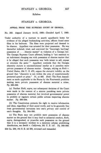
CHARGING THE ACCUMULATORTo check or charge the accumulator the following equipment is required:6. Adjust the regulator on the nitrogen bottle to 600psi/42 bar. Accumulator tester (Part Number 02835).NOTE: Charging assembly (P/N 31254—includes a regulator, hose and fitting). Nitrogen bottle with an 800 psi/56 bar minimumcharge.It may be necessary to set the regulator at 650–700 psi/45–48 bar to overcome any pressure dropthrough the charging system.1. On charge valves containing 5/8 inch hex lockingnuts, first loosen the locking nut 1-1/2 turns.2. Holding the chuck end of the Stanley tester (P/N02835), turn the gauge fully counterclockwise toensure the stem inside the chuck is completely retracted.3. Thread the tester onto the charging valve of the toolaccumulator (do not advance the gauge end into thechuck end. Turn as a unit). Seat the chuck on theaccumulator charging valve and hand tighten only.4. Advance the valve stem by turning the gauge endclockwise.5. Connect the charging assembly to the valve on thetester.7. Open the valve on the charging assembly hose.When the tester gauge reads 600–700 psi/42–48bar, close the valve on the charging assembly hoseand remove the charging valve.8. Turn the gauge end of the tester fully counterclockwise to retract the plunger in the chuck. Remove thetester from the charger valve.9. On charge valves containing 5/8 inch hex lockingnuts, tighten the locking nut.TESTING THE ACCUMULATOR1. Follow Steps 1 through 4 under CHARGING THEACCUMULATOR.2. Read the pressure on the gauge (pressure shouldbe between 500–600 psi/35–42 bar).3. If the pressure is low, recharge the tool.Figure 2. Charging the AccumulatorSD67 User Manual 13
SPECIFICATIONSCapacity (Spike Head).1.9 in dia/4.8 cm diaPressure Range Nominal. 1500 psi/103 barPressure Range Max. 2500 psi/172 barBlows Per Minute.1300 to 1800Maximum Back Pressure. 250 psi/17 barFlow Range. 7–10 gpm/26–38 lpmPorting.-8 SAE O-ringCouplers.HTMA/EHTMA Flush Face Type Male & FemaleConnect Size and Type.3/8 in. Male Pipe AdapterHose Whips. YesWeightAnti-Vibration Handle Model.67 lbs/30 kgAnti-Vibration Handle w/ Extended Foot Model.68 lbs/31 kgOverall Length – Standard Foot. 25.25 in/64 cmOverall Length – Extended Foot. 28.75 in/73 cmOverall Width – Anti-Vibration Handle. 16 in/40.6 cmMaximum Fluid Temperature. 140 F/60 CEHTMA Category.“C” (20 lpm@ 138 bar) or “D” (30 lpm@ 138 bar)Noise Level. Lwa 106Vibration Level.20.0 m/s2ACCESSORIES (SECONDARY FOOT & CUPS)Special spikes listed below may require the use of a special Stanley recommends that thischange be performed by a authospike drive foot with changeable cups.rized service centerIf you have a spike driver model SD67101 or SD67101B and would like toconvert it to drive special spikes listed below you must purchase both theFOOT P/N-23342 and one of the appropriate CUPS listed below.If you have a spike driver model SD67141 or SD67141B and would like toconvert it to drive special spikes listed below you must purchase both theFOOT P/N-28206 and one of the appropriate CUPS listed below.Spike Driver Foot (Standard) for screw on cups P/N-23342Spike Driver Foot (Extended) for screw on cups P/N-28206Dome Head Spike Cup P/N-25525Hairpin Cup P/N-23345Cutspike Cup P/N-23344SPECIAL TOOLSSpike Driver FootSpike CupsO-ring Tool Kit.04337Split Rings (Used with 04910).04908Spacer.04909Flow Sleeve Removal Tube (Used with 04908 & 05508).04910Accumulator Disassembly Tool (Used with 04910).05508Accumulator Cylinder Puller.
Stanley Hydraulic Tools recommends that servicing of hydraulic tools, other than routine maintenance, must be performed by an authorized and certified dealer. Please read the following warning. For the nearest authorized and certified dealer, call Stanley Hydraulic Tools at the number listed on the back of this