Transcription
Buehler’sGuide toMaterialsPreparationThe Science Behind MaterialsPreparation and Analysis TM
IntroductionSir Henry Clifton Sorby “Anything approaching to aburnished (smeared) surfaceof polished scratches is fatalto good results.” Scientist - Sheffield, England “Father” of Petrographyand Metallography Understood Effect ofAbrasion on Microstructure
IntroductionPreparation Requirements: ToSee the True Microstructure Remove cutting, grinding andpolishing related deformation Avoid thermal damage Avoid edge rounding Minimize relief and smearing Produce scratch-free surfaces
IntroductionPreparation SequenceEach Step Must be Performed Properly SamplingSectioningMounting (if needed)GrindingPolishingEtching (if needed)
SamplingDesignating Sampling Planes1. Transverse section2. Longitudinal “planar” section parallel to therolled surface3. Longitudinal section perpendicular to the rolledsurfaceglinlRo123ctri ednio
SectioningSectioning Sample a large component or part byremoving a suitably-sized specimen fromthe larger mass at the desired location andorientation Sectioning plane should be as near to thedesired location as possibleAggressive cutting methods will produce excessivedamage that must be removed
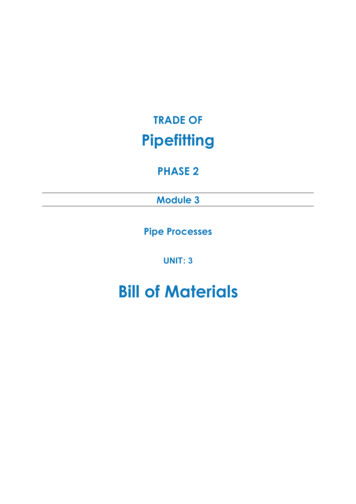
Sectioning100 µmExamples of damage (arrows) from sectioning. Left: cutsurface in CP Ti (mod. Weck’s reagent) on a planeperpendicular to the cut; Right: residual sectioning damage inthe plane-of-polish of a CP Ti specimen (Kroll’s reagent).
SectioningHeat-affected zone (left) and melting at the surface (right,arrows) due to abrasive sectioning A2 tool steel without acoolant (nital etch). The cut surface was Ni plated aftercutting perpendicular to the first cut (using coolant).
SectioningSectioning Machines
SectioningSectioning Parameters Equipment (abrasive cut-off, precision saw) Blade, Wheel (SiC, Al2O3, CBN, diamond) Operating Variables:––––LoadSpeedFeed RateContact Area CoolantNote: Delicate materials may require encapsulation
SectioningPrecision Saws Precision positioningSmall kerf lossDiamond blades, thin abrasive wheelsApplications– Delicate components– Ceramics, Carbides, Nitrides– Biomaterials
Mounting of SpecimensWhy Mount Specimens? Protect edges during preparation process Protect delicate samples Increase life of polishing surfaces Uniformity of shape and size for automation Simplify specimen identification
Mounting of SpecimensTo Maximize Edge Preservation Select the best mounting compound – EpoMet resin Use a press that cools under pressure Plate edge with a protective metal – EdgeMet Kit Add a filler material to cast resins – Flat Edge Filler Use nappless polishing surfaces
Introduction“Hot” Mounting Presses
Mounting of SpecimensSelecting a “Hot” Mounting CompoundPhenolic (PhenoCure )Acrylics (TransOptic ) Lowest PriceHigh ShrinkagePoor Edge RetentionPoor Resistance to Hot EtchantsEpoxy (EpoMet ) Superb Edge RetentionLow ShrinkageResistant to Heat and ChemicalsAbrasion Rate Matches MetalsTransparentLong Curing CycleHigh ShrinkageDefect ProneLow Chemical ResistancePoor Heat Resistance
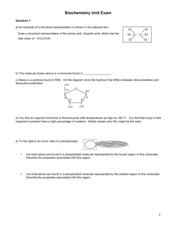
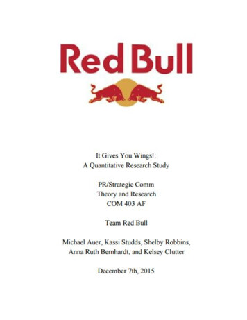
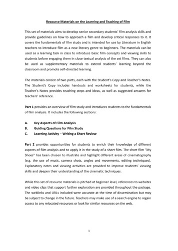
Edge RetentionSalt-bath nitrided 1215 carbon steelmounted in a) Epomet resin, b) phenolicresin; and c) methyl methacrylate resin andall prepared in the same holder revealingvariations in edge retention (nital etch). Thearrows point to the iron nitride surface layer.The needle-like particles are nitrides.
Mounting of SpecimensCastable Mounting“Cold Mounting” Acrylic Resins– VariDur– SamplKwick Epoxy Resins–––––EpoKwick EpoxiCure EpoThin EpoColor EpoHeat
Mounting of SpecimensSelecting a Castable ResinAcrylic ResinsEpoxy Resins Low Cost Low Shrinkage Rapid Cure Transparent Poor Edge Retention Adheres to Specimen Strong Exothermic Reaction Solvent Resistant High Shrinkage Moderate to slow cure Strong Odor Will Flow into Cracks andVoids (under vacuum)
Mounting of SpecimensCastable Resin Processing Factors Specimens must be cleaned and driedDo not use products beyond their shelf lifeMix resin and hardener by specified weightsResin and hardener must be mixed carefullyLarge epoxy volumes generate high heatTo reduce exotherm, use conductive moldLarge specimen size increases cure time
IntroductionGrinding / Polishing
GrindingInitial Grinding Step Goals– Remove the damage resulting from sectioning– Establish a planar surface– Reach a specific plane close to a desiredarea/featureExtent of sectioning damage determines theselection of the initial abrasive size
GrindingSubsequent Steps Remove damage from previous step(s) Decreasing abrasive size– Depth of damage decreases– Removal rate decreases Depth of damage is greater for softmaterials than hard materials
PolishingFinal Polishing Remove any remaining damage or smear Produce a lustrous, scratch-free surface Maintain edge retention and flatness Yield the true structure with sharpness and goodcontrast
Polishing ProblemsExamples of poor (a) relief control and(b) good relief control around voids in abraze (glyceregia etch) and “comettails” at nitrides in H13 tool steel(Nomarski DIC, as polished), shownabove.
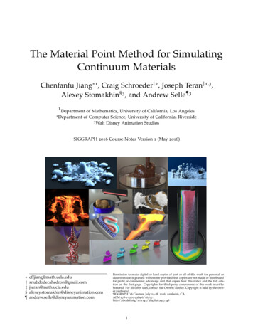
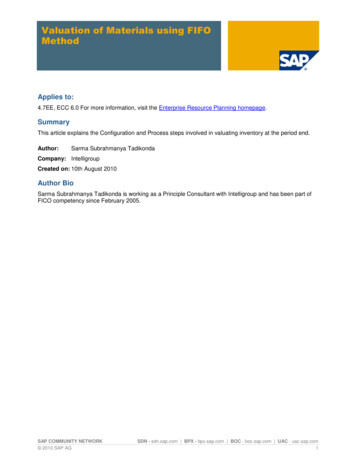
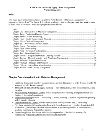
Polishing ProblemsSiC embedded in Pb (after 1-µm diam)After 3 min. polish with 0.05-µm Al2O3Embedding ofSiC abrasive isa commonproblem withlow-meltingmetals.Polishing withdiamondabrasive doesnot remove theembeddedparticles, butalumina does.5 min polish with 0.05-µm Al2O3Vibratory polish, SiO2, Pollack’s etch
Polishing ProblemsThis shrinkage gap caused bleed out of water after drying whichobscures detail and creates confusion.
Polishing ProblemsImproper drying has left spots of water on the surface. DIC
Grinding / PolishingPreparation Parameters Abrasive type, size and amountWorking surface (pad, cloth, etc.)Wheel and head speeds and directionsHead positionForce applied to specimensIndividual force or central forceLubricationTime
Grinding / PolishingAbrasives Alumina (powders, suspensions) Diamond (paste, suspensions, aerosols)(natural or synthetic; monocrystalline or polycrystalline) Colloidal silica (pH 9.5) Magnesium oxide (limited use) Cerium oxide (glass)
Grinding / PolishingMasterPrep Alumina and MasterMet Colloidal Silica Both are excellent for most metals and non-metalsMasterMet Colloidal Silica Preferred for refractory metals, polymers, sintered carbidesand aluminum alloys Unsuitable for precious metals; will etch Mg alloys and stainspearlitic cast irons; causes etching problems with stainless steelsand Ni-base superalloys when using etchants with Cl- ionsMasterPrep Alumina Suspension Free from etching, cleaning and staining problems Sol-gel processing yields agglomeration-free suspension – farbetter than calcined aluminas
Grinding / PolishingWheel and Head: Direction Contra is slightly more aggressive Complementary tends to throw abrasive off the wheel Most methods use a combination of directionsContraComp
Grinding / PolishingCentral or Individual ForceCentral Force– Cannot remove any specimens untilpreparation is complete– Yields best flatness and edge retentionIndividual Force– One or more specimens can beprepared– Can examine specimens easily duringpreparation– Easy to remove etch or repeat last partof cycle
Grinding / PolishingTime Each step must remove the deformationfrom the previous step Increase time; increase material removal Smaller jumps in abrasive size, shortertimes required Increases in specimen surface area mayrequire longer times
Grinding / PolishingTraditional MethodSurfaceAbrasive/SizeLoad Lb. (N)/SpecimenBase Speed(rpm)/DirectionTime(min:sec)CarbiMet 120 (P120) SiC*6 (27)240 – 300/Comp.Until planeCarbiMet240 (P280) SiC*6 (27)240 – 300/Comp.1:00CarbiMet320 (P400) SiC*6 (27)240 – 300/Comp.1:00CarbiMet400 (P600) SiC*6 (27)240 – 300/Comp.1:00CarbiMet600 (P1200) SiC*6 (27)240 – 300/Comp.1:00Canvas6-µm diamond paste6 (27)120 - 150/Comp.2:00Billiard1-µm diamond paste6 (27)120 - 150/Comp.2:00MicroCloth 0.05-µm aluminaslurry6 (27)120 - 150/Comp.2:00Based on 1 ¼ mount size *Water cooled
Grinding / PolishingContemporary MethodSurfaceAbrasive/SizeLoad Lb. (N)/SpecimenBase Speed(rpm)/DirectionTime(min:sec)CarbiMetpaper180, 240 or 320(P180, P240, or P400)SiC, water cooled6 (27)240 – 300Comp.Until planeUltraPol 9-µm MetaDi Supreme diamondsuspension6 (27)120 – 150Comp.5:00TriDent 3-µm MetaDi Supremediamond suspension6 (27)120 – 150Comp.4:00ChemoMet 0.05-µm MasterPrep alumina suspension6 (27)120 – 150Contra*2:00Based on 1 ¼ mount size*Use contra only with low-speed heads ( 100 rpm)
Preparation ProceduresFor Preparation, Metals Are GroupedAccording to Like Characteristics
Preparation ProceduresProcedure Development Materials are grouped by commoncharacteristics; periodic table used as a guide Primary equipment used for development– 8” (200 mm) platen– six 1.25” (30 mm) diameter specimens– central force holder
Copper, Nickel and CobaltCopper ProcedureSurfaceCarbiMetUltraPolTexMet 1000TriDentMicroClothAbrasive/Size320- (P400) grit SiCWater cooled6-µm MetaDi Supremediamond suspension3-µm MetaDi Supremediamond suspension1-µm MetaDi Supremediamond suspension0.05-µm MasterMetColloidal silicaLoad Lb.(N)/Specimen6 (27)6 (27)6 (27)6 (27)5 (22)Base SpeedTime(rpm)/Direction Untilplane5:003:002:002:00
Copper, Nickel and CobaltMaterial UNS C52400ASTM B103SAE J461Cu – 0.16 P - 10 SnPhosphor BronzeEtchant Klemm’s III reagentDescription Dendritic structure ofchill-cast phosphorbronze
Copper, Nickel and CobaltMaterial Cartridge brassCu - 30ZnEtchant Klemm’s IIIDescription Wrought cartridgebrass, cold reduced50% and annealed at704 ºC producingequiaxed alpha grainscontaining annealingtwins. Viewed withcross polarized lightand sensitive tint. 50X.
Copper, Nickel and CobaltMaterial Eutectoid aluminumbronzeCu - 11.8AlDescription Wrought, eutectoidaluminum bronze, heattreated to formmartensite (900 C-1h,WQ). Viewed withcross polarized light.
Ferrous MetalsSteel ProcedureSurfaceCarbiMet paperApexHercules Hrigid grinding diskTriDent clothMicroCloth padAbrasive/Size240- (P280) grit SiCWater cooled9-µm MetaDi Supremediamond suspension3-µm MetaDi Supremediamond suspension0.05-µm MasterPrepalumina suspensionLoad Lb.(N)/Specimen6 (27)6 (27)6 (27)6 (27)Base SpeedTime(rpm)/Direction ne5:003:001:30
Ferrous MetalsMaterial UNS K11430ASTM A588C 0.15 Cr 0.52 Cu0.32 Mn 1.05 Si 0.22V 0.6 balance FeEtchant 4% picral followed by2% nitalDescription Hot-rolled plate steeletched to reveal amoderately “banded”structure of ferrite andpearlite.
Ferrous MetalsMaterial UNS J04001AMS 1040C 0.4 Mn 0.85Si 0.6 balance FeEtchant 2% nitalDescription Microstructure ofannealed carbonsteel revealingferrite andpearlite.
Ferrous MetalsMaterial UNS G40270SAE 4027C 0.27 Mn 0.80 Mo0.25 Si 0.25 balance FeEtchant 2% nitalDescription Microstructure of hotrolled alloy steelrevealing a bainiticstructure with a fewpatches of pearlite,acicular ferrite andsome patches ofproeutectoid ferrite.
Ferrous MetalsStainless Steel ProcedureSurfaceCarbiMet paperUltraPol clothTriDent clothChemoMet padAbrasive/Size240- (P280) grit SiCWater cooled9-µm MetaDi Supremediamond suspension3-µm MetaDi Supremediamond suspension0.05-µm MasterPrepalumina suspensionLoad Lb. (N)/Base SpeedTimeSpecimen(rpm)/Direction (min:sec)6 (27)6 (27)6 (27)6 :005:002:00
Ferrous MetalsMaterial UNS S41600AISI 416 (CTC P70)C 0.10 Cr 13.0 S 0.15balance FeEtchant Beraha’s CdS reagentDescription Microstructure of “freemachining” martensiticstainless steel in thequenched and temperedcondition. Note: grayelongated sulfideinclusions, white deltaferrite and martensiticmatrix. 500X.
Ferrous MetalsMaterial Custom Flo 302 HQFe- 0.08C-18Cr-9Ni3.5CuEtchant Tint etched withBeraha’s BI reagentDescription Microstructure of hotrolled and solutionannealed and agedprecipitation hardenedstainless steelrevealing a fullyaustenitic matrix.Magnification bar is100 µm long.
Ferrous MetalsCast Iron ProcedureSurfaceCarbiMet paperUltraPol clothTexMet 1000 padTriDent clothChemoMet padAbrasive/Size240- (P280) grit SiCWater cooled9-µm MetaDi Supremediamond suspension3-µm MetaDi Supremediamond suspension1-µm MetaDi Supremediamond suspension0.05-µm MasterPrepalumina suspensionLoad Lb. (N)/Base SpeedTimeSpecimen(rpm)/Direction (min:sec)6 (27)6 (27)6 (27)6 (27)6 plane5:004:003:002:00
Ferrous MetalsMaterial Pearlitic Ductile IronEtchant Beraha’s CdSreagentDescription Microstructure ofpearlitic ductile ironcontaining graphitenodules surroundedby ferrite. Viewedwith polarized lightplus sensitive tint.500X.
Ferrous MetalsMaterial Pearlitic Gray IronEtchant Beraha’s CdSreagentDescription Microstructure ofpearlitic gray castiron containingferrite near theflakes.
Precious MetalsPrecious Metals ProcedureSurfaceAbrasive/SizeLoad Lb.(N)/SpecimenCarbiMet220- to 320- (P240 to P400)grit SiC, water cooled3 (13)TexMet 15009-µm MetaDi II diamondpaste*3 (13)TexMet 1500TexMet 1500MicroCloth3-µm MetaDi IIdiamond paste*1-µm MetaDi IIdiamond paste*0.05-µm MasterPrepAlumina* Use water as the lubricant, but keep the pad relatively dry.3 (13)3 (13)2 (9)Base SpeedTime(rpm)/Direction 40Comp.100-150Comp.Untilplane5:003:002:002:00
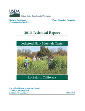
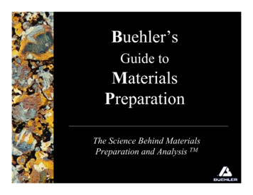
Precious MetalsMaterial Fine Silver, 100% AgEtchant Equal parts of 10%NaCN and 10%ammonium persulfateDescription Equiaxed FCC grainstructure withannealing twins
Precious MetalsMaterial 18-k Gold, 75 Au –22 Ag – 3 NiEtchant Equal parts of 10%NaCN and H2O2(30% conc.).Description Equiaxed FCC grainswith annealing twins.Specimen was attackpolished.
Precious MetalsMaterial Paliney 7 (35% Pd –30% Ag – 14% Cu –10% Pt – 10% Au
Salt-bath nitrided 1215 carbon steel mounted in a) Epomet resin, b) phenolic resin; and c) methyl methacrylate resin and all prepared in the same holder revealing variations in edge retention (nital etch). The arrows point to the iron nitride surface layer. The needle-like particles are nitrides. Mounting of