Transcription
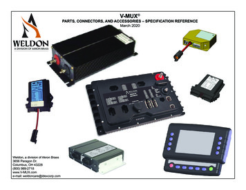
V-MUX PARTS, CONNECTORS, AND ACCESSORIES – SPECIFICATION REFERENCEMarch 2020Weldon, a division of Akron Brass3656 Paragon Dr.Columbus, OH 43228(800) 989-2718www.V-MUX.come-mail: weldoncare@idexcorp.com
V-MUX Input/Output nodes 12/24 Volt 120 AmpHercules High Content HCN 6060settable: 16-20 wired switch Inputssettable: 0-4 wired sensor Inputs(16) 13-Amp 12V Outputs(12) 4-Amp 12V Outputs(4) 4-Amp Ground Outputs------ Pages 9-10 ------ 12/24 Volt 120 AmpHercules (original) 6000(16) wired switch Inputs(3) wired sensor Inputs(16) 10.5-Amp 12V Outputs(8) 4-Amp 12V Outputs(2) 4-Amp Ground Outputs------ Pages 11-12 ------ 12/24 Volt 100 Amp capacity8x16 CAN 6030-2000(8) wired switch Inputs(2) wired sensor Inputs(16) 13-Amp 12V Outputs(2) 4-Amp Ground Outputssupports V-MUX and ES-Key CAN------ Page 13 ------Mini 4x12 6010(4) wired switch Inputs(1) wired sensor Input(12) 7.5-Amp 12V Outputs------ Page 14 ------ 12 Volt only 55 AmpMini 16x0 6020(16) wired switch Inputs(0) Outputs 12/24 Volt------ Page 15 ------2Climate Control Module0N70-1519-xx(3) wired switch inputs(2) wired sensor inputs(8) load Outputs(1) control Out------ Page 16 ----- 12 Volt only 66 Amp
V-MUX system nodes: 12/24 VoltVDR/Gateway 6444with 6204 Occupant Indicator--- Pages 20-21 ---PODS Switch Controller 6310with 6311 button modules--- Pages 18-19 -- 12/24 Volt 12/24 VoltVista IV 6240Display center with Touchscreen option(8) menu driven buttons(7) permanent legend buttons(4) video inputs--- Page 17 ---3
V-MUX Accessories (Optional components for V-MUX applications)0U10-0715-00VFD Information Display - 2 lines x 20 characters. Text only.------ Page 23 ------0R13-0614-000R13-2557-00Air Temperature Sensor, -20 to 200 F------ Page 24 ------40R00-23725-00Amperage Sensor (Hall Effect type)------ Page 24 ------
V-MUX OEM and Field Service Tools6111-0000-00 USB transceiver (upgrade)Transceiver and cables only; no kit. This part is intended asan upgrade to existing V-MUX field service kits. It shouldnot be ordered as an initial item.6131-0000-00 V-MUX USB Field Service kit.Boxed kit: includes #6111 USB transceiver, USBcable, V-MUX hook-up cable, One-on-one adaptersfor nodes, Pin extractor tools, Jumper wires, Diagnostics and Downloader software.6151-0000-00 V-MUX USB OEM kit.Boxed kit: Includes the entire 6131 Field Service kitplus V-MUX System Designer software.included adapters:#0L40-1244-00 Hercules adapter#0L40-1635-00 Mini adapter#0L40-2111-00 Gateway adapterNOTE: V-MUX Service kit software is designed foruse with computers running Microsoft Windows XP, Vista, 7, 8.1, 10 operating systems.Includes:(1) USB transceiver box(1) USB 3-ft cable (computer to transceiver)(1) #0L20-1617-00 15-ft cable (transceiver to V-MUX)0K26-1260-000411-310-1605Pin removal tool16-18 AWGDeutsch HDT48-00hand-held crimp tool0K26-2064-00(This item not included withfield service kits. Must bepurchased separately)0K26-1261-000411-240-2005Pin removal tool20-24 AWGPin removal tools are included inthe field service kit, but it is a goodidea to have a supply of spares.6190-0000-00 V-MUX Training(On-site training – for both OEM and Service)5Windows is a registered trademark of Microsoft Corporation in the United States and other countries.
V-MUX Connector PartsWeldon and TE-Deutsch part number Cross- ReferenceWeldon #Deutsch #DescriptionWeldon #Deutsch #Description0K26-1261-000411-240-2005TOOL CONTACT REMOVAL 20/22 AWG (RED)0K15-1145-00JS16-00RECEPTACLE, IN-LINE JIFFY SPLICE0K26-1260-000411-310-1605TOOL CONTACT REMOVAL 16/18 AWG (BLUE)0K26-2064-00HDT48-00TOOL, HAND CRIMP FOR DEUTSCH WIRE CONTACTSW12SLOCK, WEDGE, ORANGE, 12 POS -- SOCKETS0K70-2082-000413-204-2005SEALING PLUG 20/22 AWG (RED)0K18-2341-000K70-2060-000413-217-1605SEALING PLUG 16/18 AWG (WHITE)0K18-1193-00W2PLOCK, WEDGE, 2 POS -- PINS0K18-1785-00W3PLOCK, WEDGE, 3 POS -- PINS0K18-2059-00W3S-1939-P012LOCK, WEDGE, BLUE, KEYED 3 POS -- SOCKETS0K18-2058-00W3S-P012LOCK, WEDGE, GREEN, KEYED 3 POS -- SOCKETS0K18-1438-00W4PLOCK, WEDGE, GREEN, 4 POS -- PINS0K18-1437-00W4SLOCK, WEDGE, ORANGE, 4 POS -- SOCKETS0K18-0831-00W6PLOCK, WEDGE, 6 POS -- PINS0K18-0830-00W6SLOCK, WEDGE, 6 POS -- SOCKETS0K18-2072-00WM-12SLOCK, WEDGE, 12 POS -- PINS0K18-2585-00WM-3PLOCK, WEDGE, 3 POS -- PINS0K18-2511-00WM-4SLOCK, WEDGE, 4 POS -- SOCKETS0K18-2654-00WM-6SLOCK, WEDGE, 6 POS -- SOCKETS0K20-0837-000460-202-16141CONTACT, 16/18 AWG PIN0K20-2063-000460-202-20141CONTACT, 20/22 AWG PIN0K20-0852-000460-215-16141CONTACT, 16 AWG PIN (GREEN BAND)0K21-1001-000462-201-16141CONTACT, 16/18 AWG SOCKET0K21-2062-000462-201-20141CONTACT, 20/22 AWG SOCKET0K21-2061-000462-203-08141CONTACT, 8/10 AWG SOCKET0K00-2065-001011-026-0205MOUNTING FLANGE FOR DT04-4P0K70-1269-00114017WIRE LOCATION PLUG0K15-1192-00DT04-2PRECEPTACLE, 2 POS -- 18 AWG PINS0K15-1784-00DT04-3PRECEPTACLE, 3 POS -- 18 AWG PINS0K15-2056-00DT04-3P-P007REC. TEE, 3 POS0K15-1436-00DT04-4PRECEPTACLE, 4 POS -- 18 AWG PINS0K15-0828-00DT04-6PRECEPTACLE, 6 POS -- 18 AWG PINS0K14-2338-00DT06-12SAPLUG, 12 POS, A-KEY -- 18 AWG SOCKETS0K14-2339-00DT06-12SBPLUG, 12 POS, B-KEY -- 18 AWG SOCKETS0K14-2340-00DT06-12SCPLUG, 12 POS, C-KEY -- 18 AWG SOCKETS0K14-2057-00DT06-3S-P032PLUG, 3-POS -- 18 AWG SOCKETS0K14-1435-00DT06-4SPLUG, 4 POS -- 18 AWG SOCKETS0K14-0829-00DT06-6SPLUG, 6 POS -- 18 AWG SOCKETS0K15-2584-00DTM04-3P-E003RECEPTACLE, MINI 3 POS -- 20 AWG PINS0K14-2070-00DTM06-12SAPLUG, MINI 12 POS, A-KEY -- 20 AWG SOCKETS0K14-2071-00DTM06-12SBPLUG, MINI 12 POS, B-KEY -- 20 AWG SOCKETS0K15-2510-00DTM06-4SPLUG, MINI 4 POS -- 20 AWG SOCKETS0K14-2654-00DTM06-6SPLUG, MINI 6 POS -- 20 AWG SOCKETS0K48-2068-00HD30-24BTBOOT, HD36 SERIES CONNECTORS0K14-2066-00HD36-24-23PNCONNECTOR, 23 POS0K14-2067-00HD36-24-35PNCONNECTOR, 35 POS60K90-2056-00CONNECTOR KIT -- V-MUX NETWORK JUNCTION0K90-3111-00CONNECTOR KIT -- V-MUX NETWORK FORWARD TAP0K90-2280-00CONNECTOR KIT -- HERCULES 6000 series0K90-3462-00CONNECTOR KIT -- HERCULES HC 6060 series0K90-2281-00CONNECTOR KIT -- MINI 4x12 6010 series0K90-2282-00CONNECTOR KIT -- MINI 16x0 6020 series0K90-2286-00CONNECTOR KIT -- 8x16 6030 series0K90-2310-00CONNECTOR KIT -- VISTA IV 6240 series0K90-2311-00CONNECTOR KIT -- PODS 6300 series0L80-2653-00CONNECTOR KIT -- 6444 CAN/VDR; 6204 ORI0K90-2783-00CONNECTOR KIT -- 6204 SEAT DISPLAY ONLY0K90-2763-00CONNECTOR KIT -- CLIMATE MODULE 0N70 seriesNOTE: Deutsch components may be ordered from authorized distributors atwww.TE.com
V-MUX network layout -- backboneNetwork data cableRS-485 twisted paircable on spoolPort F0L20-1600-51 (50 ft)0L20-1600-22 (200 ft)0L20-1600-52 (500 ft)0L20-1600-13 (1000 ft)to CAN2 backboneV-MUX networkaccess port----0K90-3111-00connector kitcommunications PORT F V-MUX -- pins 7,6 CAN 1 -- pins 8,5 CAN 2 -- pins 9,4121112103CAN 2high94CAN 2highCAN 1high85CAN 1lowV-MUXhigh76V-MUXlowV-MUX networkjunction drop to node----0K90-2056-00junction kitto CAN1 backboneto rest ofnetwork nodes(32 max)NOTE: Do not use terminatingresistors in a V-MUX network.no terminationresistor7
V-MUX network layout -- terminal pins and socketsNetwork data tap0K15-1436-00DT04-4PNetwork data cableRS-485 twisted pair(viewed as lookinginto receptacle)white comms Ablack comms BPlug-in at each data Tee0K14-2057-00DT06-3S-P032(viewed as looking from rear)ACNOTEpin 1 comms A (white)pin 2 comms B (black)pin 3 OPTIONAL groundpin 4 OPTIONAL power V Battterminal pinWeldon 0K20-0837-00Deutsch 0460-202-16141At each 3-pin plug-in:It is important that the RS-485 shield wirebe pinned at C so as to provide a pathfor electrical noise to drain off. A correctly wired network will have all shieldwires common and drained at a separateground stud away from the V-MUX nodegrounds.Bpin A comms A (white)pin B comms B (black)terminal socketWeldon 0K21-1001-00Weldon 0462-201-16141pin C shield groundUse at the pin Cshield ground:Solid socket -- extendedDeutsch 0462-221-1631Use of the extended version of thesocket prevents water from infiltrating into the data Tee by way ofthe unjacketed shield wire.8
Hercules HC #6060Port A:Output ports A, B, C, D V High (13 Amp) Outputs 1-8Conn/TermKey(1) DeutschDT06-08SGray------(8) Deutsch0462-201-16141Port C:APinNamePolarityCapacity1Out 1 High Amp Vbatt13 Amp2Out 2 High Amp Vbatt13 Amp3Out 3 High Amp Vbatt13 Amp4Out 4 High Amp Vbatt13 Amp5Out 5 High Amp Vbatt13 Amp6Out 6 High Amp Vbatt13 Amp7Out 7 High Amp Vbatt13 Amp8Out 8 High Amp Vbatt13 AmpPort B:Conn/TermKey Pin(1) DeutschDT06-08SDark Gray------(8) Deutsch0462-201-16141B V High (13 Amp) Outputs 9-16NamePolarityCapacity1Out 9 High Amp Vbatt13 Amp2Out10 High Amp Vbatt13 Amp3Out 11 High Amp Vbatt13 Amp4Out 12 High Amp Vbatt13 Amp5Out 13 High Amp Vbatt13 Amp6Out 14 High Amp Vbatt13 Amp7Out 15 High Amp Vbatt13 Amp8Out 16 High Amp Vbatt13 Amp V Low (4 Amp) Outputs 1-6; Ground (4Amp) Outputs 1-2Conn/Term(1) DeutschDT06-08SGreen------(8) Deutsch0462-201-16141Port D:KeyCPinNamePolarityCapacity1Out 17 Low Amp Vbatt4 Amp2Out 18 Low Amp Vbatt4 Amp3Out 19 Low Amp Vbatt4 Amp4Out 29 Low AmpGround4 Amp5Out 30 Low AmpGround4 Amp6Out 20 Low Amp Vbatt4 Amp7Out 21 Low Amp Vbatt4 Amp8Out 22 Low Amp Vbatt4 AmpPort BPort APort C V Low (4 Amp) Outputs 7-12; Ground (4Amp) Outputs 3-4Connector(1) DeutschDT06-08SPink Gray------(8) Deutsch0462-201-16141KeyDPinNamePolarity Capacity1Out 23 Low Amp Vbatt4 Amp2Out 24 Low Amp Vbatt4 Amp3Out 25 Low Amp Vbatt4 Amp4Out 31 Low AmpGround4 Amp5Out 32 Low AmpGround4 Amp6Out 26 Low Amp Vbatt4 Amp7Out 27 Low Amp Vbatt4 Amp8Out 28 Low Amp Vbatt4 AmpPort D 12/24 Volt 120 Amp capacity9
Hercules HC #6060 -- Inputs and Communications, ports E, F, G, H, IPort E: Inputs 1-12 (signal /-)Conn/Term(1) DeutschDTM06-12SBlack------(12) Deutsch0462-201-20141KeyPinNameSignal1Input 1 V / -ground2Input 2 V / -ground3Input 3 V / -ground4Input 4 V / -ground5Input 5 V / -ground6Input 6 V / -ground7Input 7 V / -ground8Input 8 V / -ground9Input 9 V / -ground10Input 10 V / -ground11Input 11 V / -ground12Input 12 V / -groundBUSB program port: Place binary file to be loaded onto a USB flash drive.With power off plug the flash drive into the port.Power up and wait about 8 seconds for the program to load.Unplug the flash drive and cycle power Off/On.Port G: Secondary V-MUX Communications (such as the VF Display)Connector(1) DT06-04SLight Gray------(8) Deutsch0462-201-16141(1) DTM06-12SLight Gray------(12) Deutsch0462-201-2014110KeyAPinName1V-MUX 2A2V-MUX 2B3device Ground4 5V Source (500 mA) Port H: Sensor Inputs 1-4(with sensor 5V Source & Ground)Conn/TermPort EPort GPort HUSBKey(1) DTM06-06SLight Gray------(6) Deutsch0462-201-20141 PinName1Sensor 1 or Input 17 ( )2Sensor 2 or Input 18 ( )3 5V Source (500 mA)4Sensor Ground5Sensor 3 or Input 19 ( )6Sensor 4 or Input 20 ( )Port FPort IPort F: V-MUX and CAN ports; Inputs 13-16Conn/TermKeyPinNameSignal1Input 15-ground only2Input 14-ground only3not used4CAN2 L5CAN1 L6V-MUX 1B7V-MUX 1A8CAN1 H9CAN2 H10not used11Input 13-ground only12Input 16-ground onlyPort I: for external PODS button modulesConn/Term(1) DTM06-04SLight Gray------(4) Deutsch0462-201-20141(1) 0K90-2783-00(1) 0K90-2310-00(1) 0K90-2282-00(1) 0K90-3496-00(1) 0K15-2510-00(1) 0K18-2511-00(5) 0K21-2062-00Key PinName1PODS A (comms)2PODS B (comms)3PODS Ground4 Vbatt(protected source)Hercules HC Connector kit #0K90-3462-00:(1) 0K90-3595-00 8-pos DT06 KitConn kit Seatbelt Display(1) 0K14-3490-00 8-pos DT06-8SAConn kit Vista(1) 0K14-3491-00 8-pos DT06-8SBConn kit 16 Input Node(1) 0K14-3492-00 8-pos DT06-8SCConn kit 4-pos DTM06-4S(1) 0K14-3493-00 8-pos DT06-8SDConnector(4) 0K18-3494-00 8-position WS8Lock/wedge(26) 0K21-1001-00 Term AWG 18-16Pins
high capacity outputspinnamepolaritycapacitywireLOUT-09 VBatt10.5 Amp14/16 AWGBOUT-10 VBatt10.5 Amp14/16 AWGMOUT-11 VBatt10.5 Amp14/16 AWGCOUT-12 VBatt10.5 Amp14/16 AWGNOUT-13 VBatt10.5 Amp14/16 AWGDOUT-14 VBatt10.5 Amp14/16 AWGOOUT-15 VBatt10.5 Amp14/16 AWGPOUT-16 VBatt10.5 Amp14/16 AWGHercules #6000 Output pin assignments(viewed as looking at the node)high capacity outputspinnamepolaritycapacitywireROUT-01 VBatt10.5 Amp14/16 AWGSOUT-02 VBatt10.5 Amp14/16 AWGFOUT-03 VBatt10.5 Amp14/16 AWGTOUT-04 VBatt10.5 Amp14/16 AWGGOUT-05 VBatt10.5 Amp14/16 AWGUOUT-06 VBatt10.5 Amp14/16 AWGHOUT-07 VBatt10.5 Amp14/16 AWGVOUT-08 VBatt10.5 Amp14/16 AWGthree of the low capacityoutputs are located onthe Input-side connectorlow capacity outputspinnamepolaritycapacitywireQOUT-17 VBatt4 Amp16/18 AWGEOUT-18 VBatt4 Amp16/18 AWGAOUT-19 VBatt4 Amp16/18 AWGJOUT-20 VBatt4 Amp16/18 AWGWOUT-21 VBatt4 Amp16/18 AWGXOUT-22 VBatt4 Amp16/18 AWGKOUT-23 VBatt4 Amp16/18 AWG 12/24 Volt 120 Amp capacitypinname7Hercules Connector kit#0K90-2280-00:---includes--(1) 0K14-2066-00Output connector(1) 0K14-2067-00Input connector(28) 0K20-0837-00Output pins(25) 0K20-2063-00Input pins24low capacity outputspolaritycapacitywireOUT-24 VBatt4 Amp16/18 AWG14OUT-25GND4 Amp16/18 AWG11OUT-26GND4 Amp16/18 AWG262511
Hercules #6000 Input pin assignments(viewed as looking at the node)Hercules Connector kit #0K90-2280-00:---includes--(1) 0K14-2066-00 Output-side connector(1) 0K14-2067-00 Input-side connector(28) 0K20-0837-00 Output pins(25) 0K20-2063-00 Input pinsInputconnectorof HerculesBi-polar switch inputspinnamepolaritywire34IN-01 VBatt/GND20 AWG35IN-02 VBatt/GND20 AWG17IN-03 VBatt/GND20 AWG18IN-04 VBatt/GND20 AWG19IN-05 VBatt/GND20 AWG20IN-06 VBatt/GND20 AWG8IN-07 VBatt/GND20 AWG21IN-08 VBatt/GND20 AWG33IN-09 VBatt/GND20 AWG16IN-10 VBatt/GND20 AWG6IN-11 VBatt/GND20 AWG2IN-12 VBatt/GND20 AWG9IN-13 VBatt/GND20 AWG10IN-14 VBatt/GND20 AWG22IN-15 VBatt/GND20 AWG23IN-16 VBatt/GND20 AWGEach Input channel is programmedfor signal “ON” wisted pair A18 AWG26Comm-1Btwisted pair B18 AWG27GNDDO NOT USE13Comm-2Afor VFD (pg. 24)28Comm-2B29GNDsensor inputs (analog 0-5V)pinunused1DO NOT USE3DO NOT USEDO NOT USE12DO NOT USEDO NOT USE30DO NOT USE31DO NOT USE20 AWGpinnamerangewire32Sensor-10-5V20 AWG15Sensor-20-5V20 AWG0-5V20 AWG5Sensor-324 5V Source20 AWG4Sensor GND20 AWG
8x16 with CAN #6030-2000-00 12/24 Volt 100 Amp capacityConnector APinNamePolarity8x16 Connector kit #0K90-2286-00:---includes--(1) 0K14-2338-00 Connector(1) 0K14-2339-00 Connector(1) 0K14-2340-00 Connector(3) 0K18-2341-00 wedge-lock insert(36) 0K21-1001-00 #18 AWG socketConnector BConnector CCapacityPinNamePolarityCapacityPinNameHi-side 8 Out VBatt10.5 Amp1V-Mux comm1 Atwisted pair ANotestwisted pair B1Hi-side 1 Out VBatt10.5 Amp12Hi-side 2 Out VBatt10.5 Amp2Hi-side 9 Out VBatt10.5 Amp2V-Mux comm1 B3Hi-side 3 Out VBatt10.5 Amp3Hi-side 10 Out VBatt10.5 Amp3CAN High4Hi-side 4 Out VBatt10.5 Amp4Hi-side 11 Out VBatt10.5 Amp4Aux comm2 Afor VFD (pg 24)5Hi-side 5 Out VBatt10.5 Amp5Hi-side 12 Out VBatt10.5 Amp5Aux comm2 BDO NOT USE6Hi-side 6 Out VBatt10.5 Amp6Hi-side 13 Out VBatt10.5 Amp6CAN LowHi-side 14 Out VBatt10.5 Amp7*Analog 1 InSensor 1 (0-5V)Sensor 2 (0-5V)7Hi-side 7 Out VBatt10.5 Amp78Lo-side 1 OutGND4 Amp8Lo-side 2 OutGND4 Amp8*Analog 2 in9Input 1program /-signal9Input 4program /-signal9Analog GND10Input 2program /-signal10Input 5program /-signal105V (500mA) Outfor VFD, sensors11Input 3program /-signal11Input 6program /-signal11Gnd Outfor VFD, sensors12Unused12Unused12CAN ShieldNOTE: The two analog channels on ConnectorC Pins 7 & 8, may also be used as standardInput signal channels ( /-)13
Mini 4x12 node #6010 12 Volt only 55 Amps total capacity'B' Connector1234561211 10987Mating Connector Needed:DTM06-12SBpinnamenote1Analog 10-5V sensor2Input 2wired switch 23Input 1wired switch 14Input 4wired switch 45Comm 2Afor VFD (pg 24)6Comm 1Btwisted pair B7Comm 1Atwisted pair A8Comm 2BDO NOT USE9 Comm GND for sensor/VFD10Input 3wired switch 311 5V Source for sensor/VFD12 System GNDNOTE: All wired inputs use programmable signalpolarity ( VBatt or -Ground) set by the vehicledesigner14A-sideB-sideMini 4x12 Connector kit #0K90-2281-00:---includes--(1) 0K14-2070-00 A-side connector(1) 0K14-2071-00 B-side connector(2) 0K18-2072-00 WM12S wedge insert(26) 0K21-2062-00 #20AWG sockets(1) 0K21-2061-00 #8 AWG socket(1) 0K14-2069-00 plastic hook-uppinnamepolarity Amps1Output 1 VBatt 7.5 Amp2Output 2 VBatt 7.5 Amp3Output 3 VBatt 7.5 Amp4Output 4 VBatt 7.5 Amp5Output 5 VBatt 7.5 Amp6Output 6 VBatt 7.5 Amp7Output 7 VBatt 7.5 Amp8Output 8 VBatt 7.5 Amp9Output 9 VBatt 7.5 Amp10 Output 10 VBatt 7.5 Amp11 Output 11 VBatt 7.5 Amp12 Output 12 VBatt 7.5 Amp
Mini 16x0 (input only) node #6020'B' Connector1234561211 10987Mating Connector Needed:DTM06-12SBpinname1Input 132Input 143Input 154Input 165Comm 2A6Comm 1B7Comm 1A8Comm 2B9 Comm GND10 12V Power11 5V Source12 System GNDnotewired switch 13wired switch 14wired switch 15wired switch 16for VFD (pg 19)twisted pair Btwisted pair ADO NOT USEfor VFD (pg 19) VBattfor VFD (pg 19)A-sideB-sideMini 16x0 Connector kit #0K90-2282-00:---includes--(1) 0K14-2070-00 A-side connector(1) 0K14-2071-00 B-side connector(2) 0K18-2072-00 WM12S wedge insert(24) 0K21-2062-00 #20AWG socketspin123456789101112nameInput 1Input 2Input 3Input 4Input 5Input 6Input 7Input 8Input 9Input 10Input 11Input 12notewired switch 1wired switch 2wired switch 3wired switch 4wired switch 5wired switch 6wired switch 7wired switch 8wired switch 9wired switch 10wired switch 11wired switch 12NOTE: All wired inputs use programmable signalpolarity ( VBatt or -Ground) set by the vehicledesigner15
V-MUX Climate Control Module (CCM) -- #0N70-1519-03 (Fahrenheit), #0N70-1519-04 (Centigrade) 12 Volt 66 Amp capacity( J1 )Mating Connector Needed:Molex MINI-FIT, SR. #42816-0212Mating Terminal Needed:Molex 42815-0011 (10, 12 AWG)Molex 42815-0031 (8 AWG)Molex 42815-0041 (14, 16 AWG)female crimp terminals16( Batt )Mating Connector Needed:Deutsch DTHD06-1-4S( J3 )Mating Connector Needed:Amp Mini-Universal MATE-N-LOK #770584-1Mating Terminal Needed:0462-203-04141Mating Terminal Needed:Amp MATE-N-LOK Socket contacts #770988-1
Vista IV Display node-- #6240 series – ordering optionsComm port4Power ( VBatt)3GND411Comms A322Comms BVista III/IV Connector kit #0K90-2310-00:---includes--(1) 0K14-1435-00 4-pin connector(2) 0K18-1437-00 front insert (orange)(4) 0K21-1001-00 #18AWG socketsVista IV -- 6240 series part number ordering guide:6 2 4 A - B C D E -xxA: Video/GPS adapter(1 none; 2 6” adapter; 3 10” adapter)B: Legend Button Colors(0 Red/Blue/Green; 1 Green/Blue/Green)C: Touch Screen capable (0 No;1 Yes)D: Finish/Enclosure (1 standard; 2 sealed; 3 bezel; 4 DIN)E: Mounting Method (0 panel mount; 1 arm mount;2/3 open; 4 dash; 5 legacy for Vista III)-xx (suffix): custom options, see belowPart Number6” Arm mountif ordered separatelyp/n 0J50-1505-01Description624x-0010-00Standard Vista IV, replaces Standard Vista III624x-0110-00Standard Vista IV with Touch624x-0115-00Rear Panel Mount, replacement for 0N30-2391 & 0N30-2392624x-0144-00double-DIN dash -- Ford (E-series and F150-F550)624x-0144-02double-DIN dash -- Chevy/GMC624x-0144-03double-DIN dash -- Sprinter vans624x-0144-04double-DIN dash -- Dodge RAM624x-0130-00Vista IV Touch only with bezel, panel mountGPS/Video portGPS/Video adapter # 0L40-2806-00 (6”)0L40-2806-01 (10”)6GND (video 1)5GND (video 2)4GND (video 3)3GND (video 4)2* CAN High1** GPS Rx (gray)7Video 18Video 299Video 32101110Video 411211* CAN Low12** GPS Tx (purple)654378NOTES:(*) pins 2,11 CAN High/Low are not currently used(**) pins 1,12 GPS Rx/Tx only for Vista IV Touchscreen.17
S-MUX Switch sidemates with cable#0L40-2088-00V-MUX Network sidemates with connector#0K14-2070-00PODS Controller #6310 with PODS button modules #6311PODS Controller(#6310-0000-12 12 Volt version)(#6310-0000-24 24 Volt version)S-MUX side #1: Up to 8 switchmodules can exist on the Controller pins 7,8.For long runsuse only Weico#7704 cable.#0L40-2088-00controller cable assembly(see next page for details)Use Module-to-modulecable assembly#DTM06-4SPODS Connector kit #0K90-2311-00:---includes--(1) 0L40-2088-00 cable assembly(1) 0K14-2070-00 B-side connector(1) 0K18-2072-00 wedgelock insert, orange(2) 4-pin miniature plug(2) insert for plugButton LabelsV-MUX data onmodule#6311-0300-00#0Q20-1736-00Adhesive label paper -- 88 Die-cut labels for button legendsInitially blank -- Create button text & background with a Color Laser Printer18connector#0K14-2070-00S-MUX side #2: Up to 8 switchmodules can exist on the Controller pins 9,10.PODS info is continuedon next page.
PODS button modules #6311 with PODS Controller #6310#0L40-2088-00 PODS controller cable assemblyIncludes two 10-ft. cable leads with ferrite RFI protection–Controller to button modules.Either lead or both may be used. Order is unimportant.#6311-0300-00 (3-button module)#6311-0400-00 (4-button module)Connector view from rear of module.Cut length as neededNOTE: This part as ordered has no end termination of the cableleads. End fitting(s) Weldon #0K15-2510-00 (Deutsch DTM06-4S)are provided with the Connector kit #0K90-2311-000K15-2510-00Deutsch #DTM06-4S4-pin miniature plugAssembly instructions:1) Remove insulation 1½” from end2) Carefully separate the white-black twisted pairfrom the white-brown twisted pair. DO NOT mix thetwo white-colored wires.3) Crimp the shield wire common with the white wireof the white-brown pair. Both wires fit easily into theDeutsch 0462-201-20141 socket.Pin assignments – both sideswhite-black pairSHIELDwhite-brown pairshield wire1234S-MUX Comm AS-MUX Comm BGround BattNOTE: Cable shield line must becrimped common with Ground line(Pin 3, white) at DTM06-4S19
Vehicle Data Recorder (VDR) CAN Gateway -- #6444 SeriesConnector APinNameFunctionON Polarity *1Park Brakeswitch ON/OFF VBatt/GND2Service Brakeswitch ON/OFF VBatt/GND3E-Masterswitch ON/OFF VBatt/GND4CAN2-LOJ1939 comms 2signal low5CAN1-LOJ1939 comms 1signal low6Comm 1BV-MUX/ORI pin 2signal low7Comm 1AV-MUX/ORI pin 1signal high8CAN1-HIJ1939 comms 1signal high9CAN2-HIJ1939 comms 2signal high10Power (12/24V)System Power VBatt11Red Indicatorwarning output VBatt12GroundSystem GroundGNDConnector BPinNameFunctionConnectorAUSB port tocomputer via adpter#0L40-2597-00ConnectorB6204 ORI -- pin locationsViewed as looking into back of ORI. Mateswith 0K14-2654-001 2 30K14-2071-00ON Polarity *1Seat Belt 1Seat 1 belt switch VBatt/GND2Seat Belt 2Seat 2 belt switch VBatt/GND3Seat Belt 3Seat 3 belt switch VBatt/GND4Seat Belt 4Seat 4 belt switch VBatt/GND5Seat Belt 5Seat 5 belt switch VBatt/GND6Seat Belt 6Seat 6 belt switch VBatt/GND7Occupancy 6Seat 6 occupancy switch VBatt/GND8Occupancy 5Seat 5 occupancy switch VBatt/GNDExample9Occupancy 4Seat 4 occupancy switch VBatt/GND10Occupancy 3Seat 3 occupancy switch VBatt/GNDseat 6belt switch11Occupancy 2Seat 2 occupancy switch VBatt/GND12Occupancy 1Seat 1 occupancy switch VBatt/GND* The ON Polarity for switches ( VBatt/GND) is set by the VDRConfiguration Tool software or V-MUX System Designer .20Occupant Restraint Indicator#6204 Series0K14-2070-00J19391 J19392V-MUX6444/6204Connector kit:#0L80-2653-00or to6204 ORIseat 6occupancy switchConnector B: For each seat location (Example:Seat 6) the seat belt signal pin and the seat occupancy signal pin line up vertically.6 5 4PinNamenotes1Comm 1Ato VDR pin 72Comm 1Bto VDR pin 63GNDdevice ground4Power VBatt power5Dimmer *0-32V input6Buzzer *80 mA out(ground polarity)* For Dimmer and Buzzer control, see“VDR Manual -- End User” page 24
CAN/Gateway Vehicle Data Recorder -- #6444 SeriesUSB interface cable for VDR to computer#0L40-2597-00special USB receptacleDeutsch DTM06-3Pprovided with VDRto computer USB port---- optional instructions ---fabricate a 6444 Data Port USB adapter extension (not to exceed 12 ft. length)Hardware for the adapter extension endDeutsch DTM06-3S1PinNameColor1D green2D-white3GNDblackLock wire terminals in with Deutschwedge insert WM-3Sgreen2white3blackTerminate all wires with:Deutsch 0462-201-20141 Weldon 0K21-2062-00(20 AWG terminal socket)Cut the USB device end (square connector) off of astandard USB cable and expose the internal wires.standard USB cable, less than 12 ft. lengthIMPORTANT:Connect the shield conductor ofthe USB cable to wire 3 (black wire)Computer end -- flat connector(preserve this)21
Blue Touch Static Switch Panel #6300#6300-0800-00 (eight button)#6300-0400-00 (four button)Mating connectorDeutsch DT06-12SB22pin123456789101112nameKey 5 Indicator LEDNormally Open Key 5Key 6 Indicator LEDKey 8 Indicator LEDKey 7 Indicator LED Batt VDCNormally Open Key 8Normally Open Key 7Normally Open Key 6Key Sw Common (GND)LED Backlights ( Batt)GroundMating connectorDeutsch DT06-12SAButton Labels#0Q20-1736-00 Adhesive label paper-- 88 Die-cut labels for button legendsInitially blank -- Create button text & background with a Color Laser Printerpin123456789101112nameKey 1 Indicator LEDNormally Open Key 1Key 2 Indicator LEDKey 4 Indicator LEDKey 3 Indicator LED Batt VDCNormally Open Key 4Normally Open Key 3Normally Open Key 2Key Sw Common (GND)Backlights ( Batt LED)Ground
Vacuum Fluorescent Display (VFD) #0U10-0715-00The VFD requires attachment to a programmed V-MUX host node:Hercules HC, Hercules, Mini-4x12, Mini-16x0, 8x16Connector Pin-out:top123VFD cable: A shielded cable must be used tominimize electrical noise. If ordering Weldontype 0L20-1600-xx cable, the non-insulatedshield wire should be used for the Ground.VFD 3-pin connector at rear:Weldon #0K14-2073-00 Amp #171822-3VFDpinnamematchesHercules HCpins123 5VComm 2AGroundG4G1G3matchesHerculespinsmatchesMini 4x12Mini 16x0pinsmatches8x16pins241329115910411VFD Terminating pins: use Weldon #0K21-2074-00 Amp #170204-4Dimensions in millimeters and [inches]23
air Temperature Sensor#0R13-0614-00 (3-wire for general I/O nodes)#0R13-2557-00 (2-wire for 0N70 Climate Module)Amperage Sensor (DHAB S/118) -- #0R00-3725-00connects with -- #0L40-2355-00NOTE: The combination of the 0R00-3725-00 Amperage sensor with the 0L40-2355-00connector allows the signal wire to terminate directly into the V-MUX I/O node.Ip - Primary current direction0R00-3725 sensorsensor pin assignments -- to general I/O node types24wirenamematches6060Hercules HCpinblackGroundH44911redPower 5 VDCH3241110orange0-5V signal5, 15, or 3217, 8H: 1, 2, 5, 6matches6000Herculespinmatches6010Mini 4x12pinmatches60208x16 nodepin
plus V-MUX System Designer software. included adapters: #0L40-1244-00 Hercules adapter . use with computers running Microsoft Windows . 2 POS -- 18 AWG PINS 0K15-1784-00 DT04-3P RECEPTACLE, 3 POS -- 18 AWG PINS 0K15-2056-00 DT04-3P-P007 REC. TEE, 3 POS