Transcription
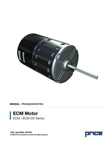
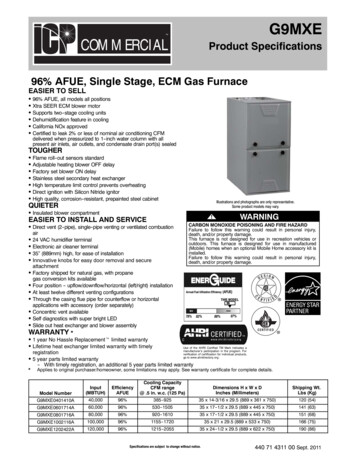
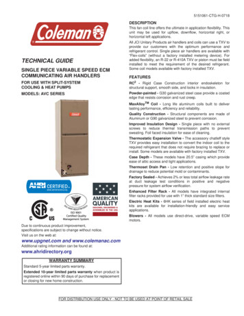
5151061-CTG-H-0718DESCRIPTIONThis fan coil line offers the ultimate in application flexibility. Thisunit may be used for upflow, downflow, horizontal right, orhorizontal left applications.TECHNICAL GUIDESINGLE PIECE VARIABLE SPEED ECMCOMMUNICATING AIR HANDLERSAll JCI Unitary Products air handlers and coils can use a TXV toprovide our customers with the optimum performance andrefrigerant control. Single piece air handlers are available with“Flex-coils” (without a factory installed metering device). Foradded flexibility, an R-22 or R-410A TXV or piston must be fieldinstalled to meet the requirement of the desired refrigerant.Some coil models available with factory installed TXV.FEATURESFOR USE WITH SPLIT-SYSTEMCOOLING & HEAT PUMPSRC2 - Rigid Case Construction interior endoskeleton forstructural support, smooth side, and locks in insulation.MODELS: AVC SERIESPowder-painted - G30 galvanized steel case provide a coatededge that resists corrosion and rust creep.MaxAlloyTM Coil - Long life aluminum coils built to deliverlasting performance, efficiency and reliability.Quality Construction - Structural components are made ofAluminum or G90 galvanized steel to prevent corrosion.Improved Insulation Design - Single piece with no externalscrews to reduce thermal transmission paths to preventsweating. Foil faced insulation for ease of cleaning.Thermostatic Expansion Valve - The accessory chatleff styleTXV provides easy installation to convert the indoor coil to therequired refrigerant that does not require brazing to replace orinstall. Some models are available with factory installed TXV.Case Depth - These models have 20.5” casing which provideease of attic access and tight applications.Thermoset Drain Pan - Low retention and positive slope fordrainage to reduce potential mold or contaminants.Factory Sealed - Achieves 2% or less total airflow leakage rateat duct leakage test conditions in positive and negativepressure for system airflow verification.Enhanced Filter Rack - All models have integrated internalfilter racks provided for use with 1” thick standard size filters.Electric Heat Kits - 6HK series of field installed electric heatkits are available for installation-friendly and easy serviceapplications. Blowers - All models use direct-drive, variable speed ECMmotors.Due to continuous product improvement,specifications are subject to change without notice.Visit us on the web at:www.upgnet.com and www.colemanac.comAdditional rating information can be found at:www.ahridirectory.orgWARRANTY SUMMARYStandard 5-year limited parts warranty.Extended 10-year limited parts warranty when product isregistered online within 90 days of purchase for replacementor closing for new home construction.FOR DISTRIBUTION USE ONLY - NOT TO BE USED AT POINT OF RETAIL SALE
5151061-CTG-H-0718LIST OF SECTIONSDESCRIPTION . . . . . . . . . . . . . . . . . . . . . . . . . . . . . . . . . . . . . . . . . . 1FEATURES . . . . . . . . . . . . . . . . . . . . . . . . . . . . . . . . . . . . . . . . . . . . 1NOMENCLATURE . . . . . . . . . . . . . . . . . . . . . . . . . . . . . . . . . . . . . . . 2DIMENSIONS & DUCT CONNECTION DIMENSIONS . . . . . . . . . . . 3DIMENSIONS . . . . . . . . . . . . . . . . . . . . . . . . . . . . . . . . . . . . . . . . . . . 3COIL TECHNICAL DATA . . . . . . . . . . . . . . . . . . . . . . . . . . . . . . . . . 3COOLING CAPACITY . . . . . . . . . . . . . . . . . . . . . . . . . . . . . . . . . . . . 4PHYSICAL & ELECTRICAL DATA - COOLING ONLY . . . . . . . . . . 5APPLICATION FACTORS - RATED CFM VS. ACTUAL CFM . . . . . 5ELECTRICAL DATA - COOLING ONLY . . . . . . . . . . . . . . . . . . . . . . 5ELECTRICAL HEAT - MINIMUM FAN SPEED . . . . . . . . . . . . . . . . . 6ELECTRIC HEAT PERFORMANCE DATA:208/230-1-60 & 208/230-3-60 . . . . . . . . . . . . . . . . . . . . . . . . . . . . . . 6ELECTRICAL DATA FOR SINGLE SOURCEPOWER SUPPLY: 208/230-1-60 . . . . . . . . . . . . . . . . . . . . . . . . . . . . 7ELECTRICAL DATA FOR MULTI-SOURCEPOWER SUPPLY: 208/230-1-60 . . . . . . . . . . . . . . . . . . . . . . . . . . . . 9ELECTRICAL DATA FOR SINGLE SOURCEPOWER SUPPLY: 208/230-3-60 . . . . . . . . . . . . . . . . . . . . . . . . . . . 10ELECTRICAL DATA FOR MULTI-SOURCEPOWER SUPPLY: 208/230-3-60 . . . . . . . . . . . . . . . . . . . . . . . . . . . 11POWER WIRING - LINE CONNECTIONS . . . . . . . . . . . . . . . . . . . 11ACCESSORIES . . . . . . . . . . . . . . . . . . . . . . . . . . . . . . . . . . . . . . . . 11COMBUSTIBLE FLOOR BASE ACCESSORY . . . . . . . . . . . . . . . . 12LIMITATIONS . . . . . . . . . . . . . . . . . . . . . . . . . . . . . . . . . . . . . . . . . 12TYPICAL APPLICATIONS . . . . . . . . . . . . . . . . . . . . . . . . . . . . . . . 12TYPICAL THERMOSTAT CONNECTION . . . . . . . . . . . . . . . . . . . . 13AIR FLOW DATA (CFM) . . . . . . . . . . . . . . . . . . . . . . . . . . . . . . . . . 142NOMENCLATUREPRODUCT TYPEAPOSITIONMOTOR TYPEVOPTIONSCNOMINALUNIT CAPACITY36CABINET WIDTHBTXV MAJOR REVISION)1STYLE LETTER(MINOR REVISION)NOT USED FORORDERINGAA Single Piece Air HandlerP Multi PSCE Multi Std ECMV Multi VS ECMZ Compact Up Std ECMC Communications Ready- Standard (No Options)18 1.5 Ton42 3.5 Ton24 2 Ton48 4-Ton30 2.5 Ton49 4-Ton36 3 Ton60 5-TonA 14.5"B 17.5"C 21.0"D 24.5"BA-BF Valve SizeX no valve1 115-1-603 208/230-3-602 208/230-1-604 460-3-601 1st Gen2 2nd Genetc.A Style AB Style Betc.Johnson Controls Unitary Products
5151061-CTG-H-0718DIMENSIONS & DUCT CONNECTION DIMENSIONSREFRIGERANT CONNECTIONSFDRAIN CONNECTIONSBLOWERCOMPARTMENTTOP EDISCONNECTPANELCD18-5/8”7-11/32”BOTTOM INLETDIMENSIONS1-1/2”FILTER 17-1/221212124-1/2212124-1/2Wiring ntrolRefrigerantConnectionsLine SizeLiquidVapor3/47/8 (1/2)1-3/8 (1)1-23/32 (1-1/4)7/8 (1/2)3/87/81. All dimensions are in inches.2. Actual size (Conduit size in parenthesis.).COIL TECHNICAL 21AVC60CX22AVC60DX21Cooling /Heat PumpCooling /Heat PumpCooling /Heat PumpCooling /Heat PumpCooling /Heat PumpCooling /Heat PumpCooling /Heat PumpCooling /Heat PumpCooling /Heat PumpCooling /Heat PumpCooling /Heat PumpJohnson Controls Unitary ProductsRefrig.Face AreaConn. Types (Sq. ep22222222323FinsPer In.1414141414141414121412Coil Size(3) 12 x 17.1(3) 14 x 17.1(3) 18 x 17.1(3) 20 x 17.1(3) 20 x 17.1(3) 24 x 17.1(3) 24 x 17.1(3) 24 x 17.1(2)28 x 17.1(3) 28 x 17.1(3) 28 x 17.1TubeTubeFinGeometry DiameterType1 x 0.8663/8Sine Wave1 x 0.8663/8Sine Wave1 x 0.8663/8Sine Wave1 x 0.8663/8Sine Wave1 x 0.8663/8Sine Wave1 x 0.8663/8Sine Wave1 x 0.8663/8Sine Wave1 x 0.8663/8Sine Wave1 x 0.8663/8Sine Wave1 x 0.8663/8Sine Wave1 x 0.8663/8Sine Wave3
5151061-CTG-H-0718COOLING CAPACITY1ModelsRated 00AVC60D1800Entering AirDry/Wet Bulb ( F)MBH@ Evap. Temp. and Corresponding R-410A Pressure ( 543.532.786.662.843.532.81. Actual capacity varies with the outdoor AC or HP that is used with the system.2. Airflow is calculated for each system tonnage.4Johnson Controls Unitary Products
5151061-CTG-H-0718PHYSICAL & ELECTRICAL DATA - COOLING ONLYModelsBlower - Diameter x WidthHPMotorNominal RPMVoltageFull Load Amps @230VTypeFilter1SizePermanent Type KitShipping Operating Weight (lbs.)ModelsBlower - Diameter x WidthHPMotorNominal RPMVoltageFull Load Amps @230VTypeFilter1SizePermanent Type KitShipping Operating Weight (lbs.)18B24B10 x 81/3 HP1050208/2302.910 x 81/3 HP1050208/2302.916 x 20 x 11PF060191/8516 x 20 x 11PF060193/8748C11 x 103/4 HP1050208/2307.048D11 x 103/4 HP1050208/2307.020 x 20 x 11PF0602158/15022 x 20 x 11PF0603163/15330B36B10 x 810 x 81/3 HP1/2 HP10501050208/230208/2302.94.5DISPOSABLE OR PERMANENT16 x 20 x 116 x 20 x 11PF06011PF0601119/113119/11349C60C11x1011 x 103/4 HP3/4 HP10501050208/230208/2307.07.0DISPOSABLE OR PERMANENT20x20 x11PF0602158/15020 x 20 x 11PF0602156/14636C42C11 x 101/2 HP1050208/2304.511 x 101/2 HP1050208/2304.520 x 20 x 11PF0602120/11420 x 20 x 11PF0602144/13660D11 x 103/4 HP1050208/2307.022 x 20 x 11PF0603180/1701. Field supplied.kW & MBH CONVERSIONS - FOR TOTAL POWER INPUT REQUIREMENTFor a power distribution voltage that is different than the provided nominal voltage, multiply the kW and MBH data from the table by the conversionfactor in the following table.DISTRIBUTION POWER208V220V230VNOMINAL VOLTAGE240V240V240VCONVERSION FACTOR0.750.840.92APPLICATION FACTORS - RATED CFM VS. ACTUAL CFM% Of Rated Airflow (CFM)80%90%100%110%120%Capacity Factor0.960.981.001.021.03ELECTRICAL DATA - COOLING DMotor FLA1208V3.05.07.3Minimum Circuit 21515151. FLA Full Load Amps2. MOP Maximum Overcurrent Protection device; must be HACR type circuit breaker or time delay fuse. Refer to the latest edition of theNational Electric Code or in Canada the Canadian electrical Code and local codes to determine correct wire sizing.Johnson Controls Unitary Products5
5151061-CTG-H-0718ELECTRICAL HEAT - MINIMUM FAN SPEEDHeater KitNom. 46502525Air Handler Models18B24B30B36B36C42C48C48D49C60C60D2.4kW Med Lo (D)Med Lo (D)Med Lo (D)Med Lo (D)Med Lo (D)Med Lo (D)Med Lo (D)Med Lo (D)Med Lo (D)Med Lo (D)Med Lo (D)4.8kW Med Lo (D) Med (C) Med (C) Med Lo (D) Med (C) Med Lo (D)Med Lo (D)Med Lo (D)Med Lo (D)Med Lo (D)Med Lo (D)7.7kW Med (C) Med Hi (B) Med Hi (B) Med Lo (D) Med Hi (B) Med (C) Med Lo (D)Med Lo (D)Med Lo (D)Med Lo (D)Med Lo (D)9.6kWMed (C) Med Hi (B) Med Hi (B) Med Lo (D) Med Hi (B) Med (C) Med Lo (D)Med Lo (D)Med Lo (D)Med Lo (D)Med Lo �24kW––Med Hi (B) Med Hi (B) Med (C) Med Hi (B) Med (C) Med Lo (D)Med Lo (D)Med Lo (D)Med Lo (D)Med Lo (D)Med Hi (B) Med Hi (B) Med Hi (B)Hi (A)Med (C)Med (C)Med (C) Med Lo (D)Med Lo (D)Med Hi (B) Med Hi (B)Hi (A)Med (C) Med Hi (B) Med (C)–Med Hi (B)Hi (A)Hi (A)Med Hi (B)Hi (A)–––––Hi (A)Med (C)Med (C)Med Hi (B) Med Hi (B) Med Hi (B)––Med Hi (B)1. (0,1) - 0 no service disconnect OR 1 with service disconnect.2. (1,2) - 1 with service disconnect, no breaker jumper bar OR 2 with service disconnect & breaker jumper bar.3. 6HK3 3-Phase with terminal block connectors only, 6HK4 3-Phase with service disconnect.ELECTRIC HEAT PERFORMANCE DATA: 208/230-1-60 & 56HK365018256HK465020256HK46502525Total Heat4Nominal .224kWkW StagingMBHW1 OnlyW1 2(0,1) - 0 no service disconnect OR 1 with service disconnect.(1,2) - 1 with service disconnect, no breaker jumper bar OR 2 with service disconnect & breaker jumper bar.6HK3 3-Phase with terminal block connectors only, 6HK4 3-Phase with service disconnect.For different power distributions, see conversion table on Page 5.Johnson Controls Unitary Products
5151061-CTG-H-0718ELECTRICAL DATA FOR SINGLE SOURCE POWER SUPPLY: 208/230-1-60Air Handler Models18B24B30B36B36C42C48C1,2Heater 1,2)6502006Field 08090100110MOP.3Min. Circuit AmpacityContinued on next page.Johnson Controls Unitary Products7
5151061-CTG-H-0718ELECTRICAL DATA FOR SINGLE SOURCE POWER SUPPLY: 208/230-1-60 (Continued)Air Handler Models48D49C60C60D1,2Heater 66HK(1,2)6502506Field 253550608090100110253550608090100110150MOP.3Min. Circuit Ampacity1. (0,1) - maybe 0 (no service disconnect) or 1 (with service disconnect).2. (1,2) maybe 1 (with service disconnect, no breaker jumper bar) or 2 (with service disconnect & breaker jumper bar).3. MOP Maximum Overcurrent Protection device; must be HACR type circuit breaker or time delay fuse. Refer to the latest edition of theNational Electric Code or in Canada the Canadian electrical Code and local codes to determine correct wire sizing.8Johnson Controls Unitary Products
5151061-CTG-H-0718ELECTRICAL DATA FOR MULTI-SOURCE POWER SUPPLY: 208/230-1-60MOP1Min. Circuit AmpacityAir �–251. MOP Maximum Overcurrent Protection device; must be HACR type circuit breaker or time delay fuse. The 1st circuit includes blower motor amps.Refer to the latest edition of the National Electric Code or in Canada the Canadian electrical Code and local codes to determine correct wire sizing.Johnson Controls Unitary Products9
5151061-CTG-H-0718ELECTRICAL DATA FOR SINGLE SOURCE POWER SUPPLY: 208/230-3-60Air 3.134.641.6Field WiringMOP.2Min. Circuit 502525357.771.677.980801. 6HK3 3-Phase with terminal block connections only, 6HK4 3-Phase with service disconnect.2. MOP Maximum Overcurrent Protection device; must be HACR type circuit breaker or time delay fuse. The 1st circuit includes blower motor amps.Refer to the latest edition of the National Electric Code or in Canada the Canadian electrical Code and local codes to determine correct wire sizing.3. The 20kW and 25kW heater models (6HK46502025 and 6HK46502525) come with circuit breakers standard. Single source power MCA and MOP requirements aregiven here only for reference if used with field installed single point power modification.10Johnson Controls Unitary Products
5151061-CTG-H-0718ELECTRICAL DATA FOR MULTI-SOURCE POWER SUPPLY: 208/230-3-60MOP2Min. Circuit AmpacityHeaterAir HandlersModels36B36C42C48C48D49C60C60D208VHeater 35303030351. The 20kW and 25kW heater models (6HK46502025 and 6HK46502525) come with service disconnects standard.2. MOP Maximum Overcurrent Protection device; must be HACR type circuit breaker or time delay fuse. The 1st circuit includes blower motor amps.Refer to the latest edition of the National Electric Code or in Canada the Canadian electrical Code and local codes to determine correct wire sizing.POWER WIRING - LINE CONNECTIONS 3 6( (/(&75,& ( 7 237,216 08/7, 6285&( 32:(5:,7 -803(5 % 56,1*/( 6285&( 32:(5*1' 08/7, 6285&( 32:(5*1'*1'32:(56833/ 12 (/(&75,& ( 7*1' 32:(56833/ / / 32:(56833/ 7(50,1 / %/2&. 256(59,&( ',6&211(&7/ / 6'-803(5 % 5/ 6'/ / 6'/ / 6'/ &,5&8,76 21 N: N: &,5&8,76 21 N: &.7 32:(5 &.7 6833/ &.7 6'6' &,5&8,76 21 N: N: &,5&8,76 21 N: &1&1 &20321(17 &2'(6 *1' *5281' /8*6' 6(59,&( ',6&211(&7&.7 &,5&8,7&1 :,5( &211(&725 187),(/' 32:(5 :,5,1* 9 3 6( (/(&75,& ( 7 32:(5 237,2166,1*/( 6285&( 32:(532:(56833/ *1'/ / / &.7 7(50,1 / %/2&. 256(59,&( ',6&211(&7 ACCESSORIESRefer to Price Manual for specific model numbers where notshown.TXV Kits - Air handlers are shipped with “Flex-coils” without afactory installed metering device. For added flexibility, an R-22or R-410A TXV or piston can be field installed to meet yourrefrigerant choice. All TXV kits are chatleff style and require nobrazing to install. Some models are available with a factoryinstalled TXV.Electric Heaters - 6HK models shown under electrical datainclude sequential operation and temperature dual limitswitches for safe, efficient operation. Service disconnects areprovided where shown.SINGLE SOURCE POWER ACCESSORIES (SINGLE PHASE)S1-02435670000For heat kits with 2 service disconnects.S1-02435671000For heat kits with 3 service disconnects.SINGLE SOURCE POWER ACCESSORY (THREE PHASE)Contains a terminal block and wiring toS1-32436041000connect service disconnects together.Johnson Controls Unitary Products08/7, 6285&( 32:(5*1'32:(56833/ &.7 / / / / / / 6'6' Combustible Floor Base Accessory - If an electric heataccessory which is rated for greater than zero clearance tocombustible surfaces is installed in these air handlers in thedownflow operating positions on a combustible floor, one of thefollowing combustible floor base accessory models is required:S1-1FB1917, S1-1FB1921, S1-1FB1924.Breaker Moisture Seal Accessory - A clear circuit breakermoisture barrier seals the breakers from humidity and dust. Theflexibility of the clear cover allows circuit breakers to be turnedON or OFF without removing the cover. The cover firmlyattaches to the access panel around the circuit breakers withthe use of double backed adhesive tape. To ensure thatmoisture or dust does not contaminate circuit breakers, an S102435672000, Circuit Breaker, Cover Seal may be ordered.Thermostat - Compatible thermostat controls are availablethrough accessory sourcing. For optimum performance, theseoutdoor units are fully compatible with our Coleman touchscreen thermostat with proprietary (patent-pending) hexagoninterface. For more information, see the thermostat section ofthe Product Equipment Catalog.11
5151061-CTG-H-0718COMBUSTIBLE FLOOR BASE ACCESSORYAIR HANDLERDEPTHFRONTDOWNFLOWAIR HANDLERFLOORWARM AIR PLENUMwith 1” flange outon each side.BAAPPROX. 1/2”CLEARANCEALL AROUND11”PLENUM13”FLOOR OPENING1”FIBERGLASSINSULATIONCROSS SECTION (A-A) FROM SIDEFIBERGLASS TAPEunder flange.BAAAIR HANDLERWIDTHCOMBUSTIBLE FLOORBASE ACCESSORYCOMBUSTIBLEFLOOR BASEFLOORBPLENUM1”APPROX. 1/2”CLEARANCEALL AROUND1”CFLOOR OPENINGA0457-001CROSS SECTION (B-B) FROM FRONTFloor BaseModelsUsed with1FB1917AVC18B, AVC24B, AVC30B, AVC36BAVC36C, AVC42C, AVC48C, AVC49C,AVC60CAVC48D, 0C16.021.017.519.524.521.023.0TYPICAL APPLICATIONSThese units must be wired and installed in accordance with allnational and local safety codes.Voltage limits are as follows:UPFLOWDOWNFLOWHEATVoltage code208/230-1-6006HEATAir Handler VoltageNormal OperatingVoltage Range1187-253HORIZONTAL RIGHTAirflow must be within the minimum and maximum limitsapproved for electric heat, evaporator coils and outdoor units.HEAT1. Rated in accordance with ARI Standard 110, utilization range “A”.HEATHORIZONTAL LEFT12Johnson Controls Unitary Products
5151061-CTG-H-0718TYPICAL THERMOSTAT CONNECTIONCooling Models with and without Electric Heat WiringAir Handler Control WiringTypical A/C - Cooling only ApplicationsTHERMOSTATP3 ON AIRHANDLERBOARDRRGGYY / Y2W1Y1W2W2CW11 - STAGEAIR CONDITIONINGAir Handler Control WiringTypical A/C with Electric Heat ApplicationsTHERMOSTATYP3 ON AIRHANDLERBOARDRRGGYY / Y21 - STAGEAIR CONDITIONINGYP2 ON AIRHANDLERBOARDHUMEAC1 - STAGEAIR CONDITIONINGELECTRIC AIRCLEANER RELAYY1HUMIDISTAT*W2W2W1W1COOHUMIDISTAT*24V HUMIDIFIERHUMHUMC(COM)*Air Handler Control WiringTypical A/C with Cooling andElectric Heat ApplicationsHUMIDISTATC(COM)CCA0407-001Optional dehumidification humidistat switch contacts open on humidity rise.NOTES:1. “Y/Y2” Thermostat wire must be connected for full CFM and applications requiring 60 second blower off delay for SEER enhancement.2. Move HUM STAT jumper on air handler control board to YES position if humidistat is used.3. For heat pump applications - set AC/HP jumper on air handler control board to the HP position.Two-Stage Heat Pump WiringCONTROL WIRING - Air Handler & UPG HP Systems Two Stage H/P with York Guard VI Board &Copeland “Ultra Tech” Conventional Application - Not Hot Heat PumpTHERMOSTATRAIR HANDLER BOARDRG2 - STAGE SCROLL HEAT PUMPRGY2Y2Y2 OUTY / Y2Y1Y1EY1W2W2 OUTW1W1 OUTWWOOOHUMIDISTAT*HUMBSX/LX/LC (COM)CCA0408-001* Optional dehumidification humidistat switch contacts open on humidity rise.NOTES:1. “Y/Y2” Thermostat wire must be connected for full CFM and applications requiring 60 second blower off delay for SEER enhancement.2. Remove humidistat jumper on air handler control board.3. For heat pump applications - set AC/HP jumper on air handler control board to the HP position.Air Handler with Communicating AC or HPTOUCH SCREENCOMMUNICATINGCONTROLAIR HANDLERCOMMUNICATINGCONTROLAC/HEAT PUMPCOMMUNICATINGCONTROLA A A RRRCCCB-B-B-RGY/Y2Y1W2W1OHUMEACCOMA0409-001Johnson Controls Unitary Products13
AIR FLOW DATA (CFM)1Cool TapADJ 0630410CBDCDCDBCBAACC534525450475400416350Cool TapADJ Tap2ABABACBDCDCD347341293309260270228High/Low Speed Cooling and Heat Pump 9947878861780797722High/Low Speed Heat CFMHeat TapABCDHeat 50105010009501. Air handler units have been tested to UL 1995 / CSA 22.2 No. 236 standards up to 0.50" wc. external static pressure.Dry coil conditions only, tested without filters.For optimal performance, external static pressures of 0.2" to 0.5" are recommended. Heating applications tested at 0.50” w.c. esp. Above 0.5" CFM is reduced by 2% per0.1" increase in static.The ADJ tap does not affect the HEAT tap setting.Low speed cooling used only with two stage outdoor units. Speed is preset to 65% of high speed.Dehumidification speed is 85% of jumper selected COOL tap and ADJUST tap.When operating in both heat pump and electric heat modes, the airflow (CFM) will be per HEAT tap CFM values only.At some settings, LOW COOL and/or LOW HEAT airflow may be lower than what is required to op
MOTOR TYPE V P Multi PSC E Multi Std ECM V Multi VS ECM Z Compact Up Std ECM OPTIONS C C Communications Ready- Standard (No Options) NOMINAL UNIT CAPACITY 36 18 1.5 Ton 42 3.5 Ton 24 2 Ton 48 4-Ton 30 2.5 Ton 49 4-Ton 36 3 Ton 60 5-Ton CABINET WIDTH B A 14.5"
