Transcription
PREFINISH HARDWOOD FLOORINGPLANCHERS DE BOIS PRÉVERNISLIMITED WARRANTY ANDINSTALLATION GUIDELA GARANTIE LIMITÉE ETLE GUIDE D’INSTALLATIONJuin 2018lJune 2018This guide replaces and prevails over all previous versions.Ce présent guide remplace et prévaut sur toutes versions antérieures.
ENGLISHCongratulations and thank you for your Lauzonhardwood floor purchase!Since 1985, we have dedicated ourselves to marrying theartistry of finely crafted wood with new technologies tooffer hardwood floors of exceptional quality combinedwith the assurance of a thoughtful and consistent choice.We don’t cut corners. Because we know that your homeis more than an investment, it’s a privileged space ofrepose, comfort and beauty. You wouldn’t skimp on thesurfaces that carry you through life. You want them to bebeautiful, practical and healthful. We are committed tomeeting, even surpassing your expectations.“A beautiful, enduring flooring experience created withauthentic artistry, ingenuity and environmental integrity.”David Lauzon3
ENGLISHTABLE OF CONTENTSWARRANTY. . . . . . . . . . . . . . . . . . . . . . . . . . . . . . . . . . . . . . . . . . . . . . . . . . . 5CONDITIONS FOR IMPLEMENTING THE WARRANTY. . . . . . . . . . . . 5GENERAL LIMITATIONS OF WARRANTY. . . . . . . . . . . . . . . . . . . . . . . . 5SPECIFIC EXCLUSIONS TO THE WARRANTY. . . . . . . . . . . . . . . . . . . . .5CLAIM PROCEDURE . . . . . . . . . . . . . . . . . . . . . . . . . . . . . . . . . . . . . . . . . . . . 6GENERAL INSTALLATION GUIDE. . . . . . . . . . . . . . . . . . . . . . . . . . . . . . . . . 6STORAGE. . . . . . . . . . . . . . . . . . . . . . . . . . . . . . . . . . . . . . . . . . . . . . . . . . . . 6RESPONSIBILITY OF INSTALLER AND OWNER. . . . . . . . . . . . . . . . . . . 6Before the installation . . . . . . . . . . . . . . . . . . . . . . . . . . . . . . . . . . . . . . . . 6Subfloor . . . . . . . . . . . . . . . . . . . . . . . . . . . . . . . . . . . . . . . . . . . . . . . . . . . 6Subfloor moisture . . . . . . . . . . . . . . . . . . . . . . . . . . . . . . . . . . . . . . . . . . . 7INSTALLATION – GENERAL REMARKS . . . . . . . . . . . . . . . . . . . . . . . . . . 7AFTER INSTALLATION . . . . . . . . . . . . . . . . . . . . . . . . . . . . . . . . . . . . . . . . 8CUSTOMER OBLIGATIONS REGARDING THEMAINTENANCE OF A WOOD FLOOR . . . . . . . . . . . . . . . . . . . . . . . . . . . . 8PARTICULARS OF INSTALLATION TYPES . . . . . . . . . . . . . . . . . . . . . . . . . 8NAILED OR STAPLED INSTALLATION. . . . . . . . . . . . . . . . . . . . . . . . . . . 8GLUED INSTALLATION. . . . . . . . . . . . . . . . . . . . . . . . . . . . . . . . . . . . . . . 9INSTALLATION OVER A RADIANT HEAT SYSTEM. . . . . . . . . . . . . . . . . 9FLOATING INSTALLATION. . . . . . . . . . . . . . . . . . . . . . . . . . . . . . . . . . . . . 9“HERRINGBONE” PATTERN INSTALLATION. . . . . . . . . . . . . . . . . . . . . 10ANNEX A MANDATORY INSTALLATIONCONDITIONS BY PRODUCT TYPE . . . . . . . . . . . . . . . . . . . . . . . . . . . . . . 134
WARRANTYENGLISHA- Our floors have a lifetime warranty for their structural integrityB- We guarantee our floors against the total wear of their finishes, as described in the followingtable:Warranty duration, by usage and floor type when purchased.Essential CollectionAmbiance CollectionDesigner CollectionDurationLight commercial usage5 years (#1)No warrantyxxDurationResidential usage (#2)25 years 30 years 35 yearsxxx1. Light commercial usage: The warranty applies only in low activity areas and only forestablishments having no direct exterior access, such as stores in a shopping mall(where store access is via the mall’s hallways), offices, health facilities, etc. This warrantyDOES NOT COVER commercial establishments with a direct exterior access such asrestaurants, bars, clubs, and businesses and/or installations where the floors might besubjected to excessive wear.2. The warranty covers residential activities in areas of normal circulation.CONDITIONS FOR IMPLEMENTING THE WARRANTYThe warranty is non-transferable, therefore, valid only for the original customer and is subjectedto the procedures, restrictions, renunciations and exclusions outlined in this document.Taking into account that wood is a living matter, industry standards allow up to 5% of floorcomponents containing defects without considering that the whole floor is sub-standard.Lauzon’s responsibility is limited to replacing or repairing defective components – only fordefects explicitly covered by the warranty - above this 5% threshold.In order for wear to be covered by this warranty, the wear shall be clearly visible and shallcover more than 10% of the total surface of the purchased floor.This warranty will not apply to products that have not been paid in full.The warranty does not cover ANY other costs, such as (but not limited to): installation,transport, punitive damages, etc.GENERAL LIMITATIONS OF WARRANTYShould a floor component be deemed sub-standard or not acceptable with respect to grade,color, craftsmanship or finish, it should not be installed; otherwise it will be considered asaccepted “as is” by the Customer.Since the wood floor will react and interact with the environment, it shall be installed andmaintained in the appropriate environmental conditions. PLEASE refer to the table of AnnexA “MANDATORY INSTALLATION CONDITIONS BY PRODUCT TYPE” in order toidentify the recommended relative humidity level for your product.Failure to follow the installation guidelines might partially or completely void the warranty.SPECIFIC EXCLUSIONS TO THE WARRANTYDimensional changes and cracks due to floor humidity variations caused by environmentalchanges.Wear, luster variation, color variation and/or discoloration.Damages such as scratches and dents caused by impacts, friction due to heavy loads andobjects, abrasive compounds, high heel shoes, shoes with hard, rigid soles, and animals.No warranty on products sold “as is”, Tavern grade, rustic or second grade.5
ENGLISHCLAIM PROCEDUREWhen lodging a claim, the Customer shall contact the retailer where he/she purchased theLauzon product from. The Customer must have the detailed sales receipt that shows the dateof purchase, the quantity bought and the product code.Lauzon retains the right to: Inspect the floor; Take floor samples in order to perform technical analysis; Inquire as to how the product was installed; Any other inquiries relevant to the claim.Any defect shall have been brought to the attention of the retailer where the Customerpurchased the floor within 30 days following the initial purchase and/or the discovery of thedefect.Please visit our website to find a claim form to fill.www.lauzonflooring.comGENERAL INSTALLATION GUIDESTORAGEAlways store the floor and moldings in normal ambient living conditions, i.e. between 35% and55% relative humidity. Do not store in a garage, basement or other locations where the woodwould be exposed to the effects of uncontrolled humidity. Avoid uselessly opening the boxes.Do not open the boxes ends.RESPONSIBILITY OF INSTALLER AND OWNERThe installation of a hardwood floor should be done according to the floor industry’s bestpractices. This is why we are recommending that you contact a National Wood FlooringAssociation Certified Professional to install your floor. A list of active NWFA CertifiedProfessionals can be found online at www.nwfacp.orgBefore the installationEnsure and confirm that the work environment and the subfloor meet the minimal conditionsof this document; Inspect the subfloor and verify its moisture content (MC); Install your product in normal living conditions; between 35% and 55% relative humidityPerform final inspection and approbation of floor components with respect to their grade,finish, color and manufacturing quality prior to the permanent installation; Any installed floor component will be considered as accepted by the installer andthe owner – whether or not the owner is present during installation – and consequentlywill not be covered by our warranty.SubfloorBefore proceeding with the installation of your wood floor, carefully inspect the work locationin order to determine whether the subfloor and the building’s ambient environmentalconditions are acceptable. Verify the following :6 For houses that have a crawlspace or a pillar foundation Vents shall ensure a transverse ventilation so that air can freely circulateeverywhere; The foundation shall have a minimum of two vents that are open year-round andwhose combined cross-section area is equal or greater than 1.5% of the crawlspacearea;
ENGLISH Cover the crawlspace floor with a black polyethylene vapor barrier of 6 mil(6/1000 in or 0,15 mm).The wood subfloor shall be structurally sound and solidly affixed to the joists.For plywood subfloors or OSB, they shall conform to the norm “U.S. Voluntary ProductStandard PS1-07, Construction and Industrial Plywood” and/or “US Voluntary PS 2-04”and/or the standard Canadian performance norm CAN/CSA 0325.0-92Subfloor plywood thickness is determined by the joist spacing: A joist spacing of 16 in requires a plywood of 5/8 in or OSB 23/32 in or more A joist spacing of 19 in requires a tongue and groove plywood of 23/32 in or OSB23/32 in or moreIf the subfloor is a wood surface, the floor components shall be installed eitherperpendicular or at 45 degrees with respect to the joists.If the subfloor is a concrete surface, the concrete shall have a minimum compressivestrength of 3000 psi.The subfloor must be clean, flat, smooth and free of debris of any kind. Flatness toleranceis a maximum of 1/4 in (6 mm) within a radius of 10 ft. (3 m).For nailed or stapled installations, the installation of a wood subfloor vapor barrier isrecommended. Acceptable vapor barrier must be a membrane with a vapor permeability(infiltration coefficient) equal or greater than 0.7 and equal or lower than 10 when testedas per ASTM E-96 A. The installation of a vapor barrier will reduce the migration ofhumidity and related vapor problems, but it is not a guarantee that it will eliminate them. For glued installations, a sealer or a glue containing a sealer are acceptable solutions; ifthis is the chosen mode of installation, refer to the manufacturer’s technical specifications(either for the sealer or the glue containing a sealer) to know the vapor permeabilityproperties. If a combination of glue and sealer is used, make sure that the two productsare compatible.Subfloor moisture The wood subfloor moisture shall not exceed 12%. The moisture difference between the wood subfloor and the floor itself shall be : No more than 4% in floors less than 3 in wide No more than 2% in floors wider than 3 in wide The moisture evaporation rate for concrete is at most 3 lbs per 1000 ft2 / 24 hrs (ASTMF1869 calcium chloride test). If it is higher than that, use a sealer/retarder appropriatefor the specific installation.INSTALLATION – GENERAL REMARKSFor nailed or stapled installation: it is best to start from the middle of the room for rooms lessthan 20 ft. wide and mandatory to start from the middle of the room for rooms wider than 20ft. in order to spread out the expansion. Please make sure to allow enough expansion space, min3/4 in for solid and 1/2 in for engineered.Given the natural wood color variations, the installer shall work at all times with three or fouropen boxes in order to harmonize the overall look of the floor.1- Draw a guiding line parallel to the installation orientation2- Fix a straight support block in order to guide and facilitate the installation of the firstrows.3- Remove the support block and glue and nail – or staple – (depending on the chosenmode of installation) a tongue reversal piece in the groove of the first installed row andcontinue with the installation.4- To complete a row, pick a floorboard that has a length difference of at least 6 in (15 cm)with the first floorboard of the previous row, in order to avoid aligning the joints. Installthe floorboard and then use its sawed-off section to start the next row.5- Avoid joint alignment:7
ENGLISH For products of 4 in (width) or less, make sure that the joints are at least4 in (10 cm) away from each other; For products of more than 4 in (width), make sure the joints are away from eachother by more than the product width;6- Install moldings and quarter rounds by nailing them in the wall, NEVER IN THE FLOOR.AFTER INSTALLATION Install moldings and other aesthetic parts (when applicable). Clean the floor and make sure to remove any trace of glue residues. For glued installation, limit traffic and moving of furniture on the floor for therecommended duration specified by the glue manufacturer, typically 24 hours. Let the floor breathe. Do not cover with a non-porous material like plastic, rubber orvinyl.CUSTOMER OBLIGATIONS REGARDING THE MAINTENANCE OF A HARDWOOD FLOOR Maintaining the relative humidity level in your house; refer to the table of Annex A“MANDATORY INSTALLATION CONDITIONS BY PRODUCT TYPE”; Immediately wipe away any spills; Sweep or vacuum regularly; Clean your floor with product specifically designed for it; Lightly spray the cleaning product on a dry mop or sweeper. Never pour a cleaningproduct directly on your floor; Never clean your floor with a wet mop; Install a small rug or a door mat in front of every entrance in order to protect your floorfrom abrasions and humidity; regularly clean and vacuum those rugs/mats; Install small felt pads – or other soft, protective material – under furniture legs to protectthe floor from abrasion and dents; replace them regularly by new ones. Do not use hardor plastic covers; Never move any heavy objects without protecting your floor. Should you have to movea heavy object, put the object on an upside down clean rug or carpet, and gently slide itacross the floor; Never use wax, oil-based detergents or other household cleaning products on your floor.These products could damage the lustre/finishing of your floor or make them fade; theyare also likely to leave a greasy film on the floor that will make it slippery and hard toclean.For any additional information, consult our website at www.plancherslauzon.comPARTICULARS OF INSTALLATION TYPESNAILED OR STAPLED INSTALLATIONUsing a stapler is impossible when working next to a wall. Those rows will have to be donemanually, either by using a manual nailer from the top of the floorboard or by using flexibleglue. Using nonflexible glue might interfere with the natural expansion of the wood and causepermanent damage not covered by the warranty.8Make sure you follow the recommended spacing of nails or staples; please refer to the table inAnnex A “MANDATORY INSTALLATION CONDITIONS BY PRODUCT TYPE”.Ensure that each floor board is fixed at least at two different locations, no matter what lengthit is.
ENGLISHGLUED INSTALLATIONNot recommended for solid floorsUse an adhesive designed for engineered floor, but not a water-based adhesive.Refer to the glue manufacturer’s instructions to select the proper trowel.Read the glue manufacturer’s instructions to ensure its proper application.INSTALLATION OVER A RADIANT HEAT SYSTEM1. Starting up an integrated radiant heat system in a concrete sub-floor before the concrete hascompletely cured might negatively impact its structural integrity.2. Start the heating system at 2/3 of its maximum capacity for 14 to 16 days in order toget rid of any excessive humidity. Midway through the 14 to 16 days period, raise thetemperature to its maximum for 2 days.3. Once the concrete slab or the sub-floor has completely cured and is dry, shut the heatingsystem down for 1 to 2 days prior to installing the wood floor. Sub-floor temperature shallnot exceed 68 ºF (20 ºC) at installation time.4. Install the wood floor according to the appropriate installation guide directions.5. 24 to 48 hours after installation, gradually increase the heating system temperature byincrements of 10 ºF (5 ºC). Avoid a drastic and sudden raise of temperature, as it mightresult in permanent damage not covered by the warranty.6. Floor temperature shall not exceed 80 ºF (26 ºC) once the floor is installed7. Do not install rugs, carpets or furniture without any air gaps, that will not let the floorbreath.REMARK: Refer to the table in Annex A “MANDATORY INSTALLATION CONDITIONSBY PRODUCT TYPE” in order to determine whether your floor is compatible with a radiantheat system.FLOATING INSTALLATIONNot recommended for solid floorsMultiple lengths with Micro-V onlyMembraneA membrane is required for installation of a floating floor. Lauzon recommends the ‘’Tuplex’’membrane, or an equivalent product. For installation, refer to the membrane manufacturer’sinstructions.Floor1.Accurately measure the room’s dimensions and figure out the way the floor boardswill be laid out while making sure the parallel sides are equal and at the same distancefrom the walls. Leave a gap of at least ½ in (12 mm) between the floor boardsand the walls for lateral expansion and ¼ in (6 mm) at the ends of the rows forlongitudinal expansion.2.Plywood floor boards will be installed from left to right with the grooves orientedtowards the starting wall. Start by installing the first two rows simultaneously. Positiona long board in a corner on the left side of the installation.3.Apply glue on the lower side of the lateral groove of the second board and join thesecond board to the first one. The new board should be at least 5 in (13 cm) shorterthan the first one.4.Apply glue on the lower side of the end groove of the third board and join that thirdboard to the end of the first board.9
ENGLISH5.Continue the installation of the first two rows by applying glue to the lower side of thelateral and end grooves. Those rows must be perfectly straight. Keep a distance of ½ in(12 mm) from the starting wall by using small spacer blocks. Those spacers will alsoprevent floor boards movement during the rest of the installation.6.Stagger the end joints of the floating floor boards by a distance equal or larger thanthe boards width. Allow for at least three rows between end joints that are even.Firmly press the floor boards together manually, or by using a small block designedfor it. Clean and remove the excess glue with a wet rag or mineral spirit. Painter tapethat can be quickly removed - like the 3M blue 2080 tape – can also be used to fix theboards together.7.Allow the glue to dry between the first two rows before starting installation of theother rows. Remove the painter tape – if used – within two hours of its application. Alever bar can be used to press boards together after a row has been added.8.When the first two rows are firmly in place, proceed with the rest of the installationwhile leaving a ½ in gap all around the room. Clean and remove excess glue. Staggerthe end joints by at least 5 in (13 cm) throughout the installation. Use the startingboards to vary the location of end joints. Starting boards shall have a minimum lengthof at least 6 in (15 cm).9.The last row against the wall will rarely be the same width as the other rows. Cut theboards lengthwise so that the last row matches the available space (while respectingthe ½ in gap between it and the wall). Apply glue and use a lever bar to press it intoplace.10.Cut off the excess membrane so that it will not be visible after installing the moldings.Expansion rules for floating floor installation1. Plan for an expansion space next to walls, doors and vertical obstacles. The minimumrequired space is ½ in (12 mm) for continuous surfaces up to 24 ft. (7 m). A continuoussurface is defined as an area without separation or expansion joints. If the installed flooris directly joined to adjacent rooms’ floors, by a hallway or an entrance without T-shapedmolding, the width of the continuous area is the sum of the separate rooms widths or theentrance. Obstacles include cabinets, islands and the wall opposite to the starting wall.2. No continuous floor can spread more than 40 ft. (12m) of width.3. Adjacent rooms more than 16 ft. (5 m) in width connected by a door 3 ft wide or less shallbe separated by a T-shape molding.Width of continuous surfaceRequired expansion spaceUp to 24 ft. (7 m)½ in (12 mm)From 24 to 40 ft. (7 to 12 m)¾ in (20 mm)HERRINGBONE PATTERN INSTALLATIONGlued installation only1. Guiding lines set-up at 90 angle (illustration 1 ).Lauzon’s herringbone or wickerwork boards can be installed from any starting point within aroom. However, usual installation guidelines suggest starting from the middle of the room.10Should you want to use SI system units (metric) in the following examples, do not convert theimperial unit figures into metric units. The indicated metric measurements in parenthesis donot correspond exactly to the imperial measurements. In order to ensure accurate 90 et 45 angles, the metric measurements were adjusted accordingly. You can thus use either units, asindicated below.Lines X and Y must form a perfect 90 angle. In order to obtain this angle, proceed as follows:a) Draw the X line in the middle of the room using a chalk line.b) Put a tick mark in the middle of the X line. Then put another tick mark on the same Xline at 3 ft. (1.2 m) from the first tick mark.
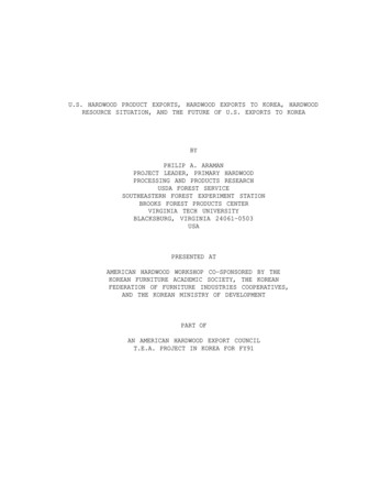
ENGLISHb)LesFaitesau centrede laparfaitlignedeX. 90 .FaitesdeuxièmemarqlignesuneX et Ymarquedoivent formerun anglePourensuiteobtenir unecet angle,procéderdeàsuivanteune zpartirladecettetracezarc deà craie.cercle d’un rayon de 5 pligneX audeuxièmecentre de lamarque,pièce à l’aided’ununcordeaub) Faites unemarqueaucentretracée.de la ligne X. Faites ensuite une deuxième marque sur cettegénéraleoulaligneYserac) From this second tick mark, draw a 5 ft. (2 m) radius arc in the general area where the Ydistancede3 pi (1,2 m)de la marqued)à uneÀlinepartirla marquecentralesur lacentrale.ligne, tracez un deuxième arc de cercle dwill bededrawn.c) À partir de cette deuxième marque, tracez un arc de cercle d’un rayon de 5 pi (2 m) dans lquicouperal’arctracéàl’étape3.d) From the central tick mark on the X line, draw a second arc with a 4 ft. (1.6 m) radiusgénérale ou la ligne Y sera tracée.thatlignewill intersectthe pararc drawnin step3.- d)Unele pointla ligneX et l’intersectiondes rayondeux dearÀ partirdepassantla marquecentralesurcentralla ligne, detracezun deuxièmearc de cercle inetotheintersectionofthetwoparfaitde90 ures(3,4etqui couperal’arc tracé à l’étape 3.arcs forms a perfect 90 angle with the X line. Verify the accuracy of all measurementslignepassantle 1,6pointcentralla ligneX etd’unl’intersectiondes deuxformera- -SiUneles(3,4mesuresexactes,tracezlignemur à l’autreenarcspassantparuand5 ft. sont/ par1,2 m,m and2 m).deunede 90 avec ladesligneX. Vérifierl’exactitudedelatouteslesmesures (3,4 et 5 pi / 1,2 m, ligneY.If all measurements are accurate, draw a line from one wall to another, going through the- Si lescentralmesuressont onexactes,tracezuneintersectionligne d’unofmurà l’autreen ispassantpar le point centtick markthe X lineand thethe twoarcs; thisyour Y line.X et l’intersection des deux arcs. Ce tracé est la ligne Y.12.2.Fora 45 installationangle installation,havedeto draw45 murs,angle working(illustration).Pouren youun willangle45 adesvous linedeveztracer2 uneligne de2. Pour installation en un angle de 45 des murs, vous devez tracer une ligne de travail en una) From the intersectionof the X and Y lines, put 2 tick marks on each line at 4 ft. (1.6 m)(illustration2).(illustration2).fromtheducentral point,for a(intersectiontotal of 4 tick desmarks.partircentralet Y), faitesdeuxmarquessura)a)ÀÀ partirdupointpointcentral(intersectionlignesdes XlignesX et Y),faitesdeuxopposéesmarquesb) Fromeachthesefour tickdemarksft. (1.6m) pointfrom thecentralquatrepoint), marquesdraw a 4 ft.au total.lignesX etY àofunedistance4 pi(4(1,6m) ducentral,lignesXm)etarcY inà theunegeneraldistancede 4thepi 45 eredrawn. central,A deline 4goingthroughthepoint centrab) À(1.6partirde chacunede cesmarques(à une distancepi (1,6m) etwoarcswillforma45 anglewiththeXandYde cercle d’un rayon de 4 pi (1,6 m) dans la zone générale ou la ligne à 45 sera tracée.duUlines.cercleVerify theaccuracyof all(1,6(1,6m) measurements.arcderayonde4 4ft.pim) dedansla zonegénéralela ligne45 sdpassantpar lesd’unpointsd’intersectiondes arcscercleet le pointcentralouformeraunàanglec) If themeasurementsare accurate,drawa linedesfrom4arcsthecentralpoint topassantparles pointsd’intersectiondem).cercleetthele intersectionpoint central formelignesX etY. Vérifiezl’exactitudedes mesurespi (1,6oflesthemesurestwo arcs.sontThis linewill betracezat a 45 uneanglewithpassantrespect parto boththeX andY s i(1,6m).This is your working line.pointcentral.Cetracéseraorientéà45 parrapportauxlignesXetY.Ils’agitdelalignede tc) Si les mesures sont exactes, tracez une ligne passant par les points d’intersecpoint central. Ce tracé sera orienté à 45 par rapport aux lignes X et Y. Il s’agit d23. Disposition des lamelles. Chaque boîte de plancher à bâtons rompus ou en vannerie de La3. Floor boards disposition. Each box of Lauzon’s herringbone boards contains an equalunnombreégal delamellestenonsà gaucheà droite.Lorsde handla misequantityof boardswithtonguesavecon theleft handside andettongueson therightside.en place des ntdelafairesansWhen installing herringbone or wickerwork floor boards, it is important not to slide fairethe glisser les lamlorsqu’onfaitanother.glisserles lamelles,peuts’accumulersur leaccumulatebordd’attaque,floorboardson oneSlidingthe floorl’adhésifboardsone oîte againstdeplancherà bâtonsrompusou enempvaglueemboîtementon the leading parfait.edge, preventing a good mesh between the boards.unun nombre égal de lamelles avec tenons à gauche et à droite. Lors de la mise en4. Install a floor board with glue on the right tongue. Position the floor board so that the edgeplancherà bâtons rompus ou en vannerie, il est important de la faire sans faireis exactly on the working line (illustration 3a and 3b ).effet,lorsqu’onfait glisserles lamelles,l’adhésifpeuts’accumulerle bordd’4. Installerune lamelleavec tenonà droite dansl’adhésif.Placezla lamelle desurfaçonà ce queunsoitemboîtementexactement surparfait.la ligne de travail (illustration 3a et 3b).4. Installer une lamelle avec tenon à droite dans l’adhésif. Placez la lamelle de fasoit exactement sur la ligne de travail (illustration 3a et 3b).113a3b5.Placez la lamelle #2 (tenon à gauche) à angle drune “flèche” (illustration 4a et 4b) pointant dansle plancher sera identique.
ENGLISH5. Install the: second-floorboardla(tongueon theleft)lamellesat a right anglefirst étéboarddéterminée, retCONSEILUne fois quepositiondes#1 etwith#2theaura(tongue on the right) to form an arrow-shaped pattern (illustration 4a and 4b) pointing indethela rightboîteet empilez-lesdanssensflooroù boardselles serontCette précautiondirection.The installationof allleotherwill followinstallées.the same l’installation.UtilisezSUGGESTION: Once the first two floor boards are installed, remove all the remaining boardsun ruban defrom the commebox and positionas they2080Mwill be installed.Thisbleu)will avoidmixingtwo du bois afin oard types duringinstallation. JAMAISUse easy toderemovepaintertape like2080M (blueto holddes e,cartape)il laissethe boards together. NEVER USE regular tape since it will leave glue residue on the boards thatenlever.Retirezle rubanfois oncel’installationterminée.is very difficultto remove.Removeunethe tapethe installationis completed.4a4b12
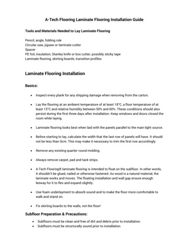
It is essential to control the pressure generated by installation tools; we stronglyrecommend to try various pressures on a board to determine the right one. The headof the nail or staple should rest on the tongue without penetrating it.ProductSolid¾ in(19 mm)InstallationGround floorlocationand upCompatible with Noradiant heat floorAllowedNailedinstallationStapledmethodSee note 1FastenersMin 1½ in (3.5 cm)16 to 22 GaEngineeredExpert ¾ in(19 mm)All floorsEngineeredup to7/16 in (11 mm)All floorsEngineeredgreater than7/16 in (11mm)All floorsYesSee note 2GluedStapledSee note 3YesSee note 4NailedStapledGluedFloatingSee notes 5 & 6YesSee note 4NailedStapledGluedFloatingSee notes 5 & 6Min 1½ in (3.5cm)18 to 22 GaMin 1¼ in (3 cm)18 to 22 GaMin 1½ in (3.5cm)18 to 22 Ga4-6 in (10-15cm)OR4 in (10 cm) forproducts morethan 5 in (13 cm)4-6 in (10-15cm)OR4 in (10 cm) forproducts morethan 5 in (13 cm)Fasteners spacing 6-8 in (15 -20 cm) 6-8 in (15 -20cm) OR4 in (10 cm) forproducts morethan 5 in (13 cm)Fasteners spacing 1-3 in (2.5-7.5cm) 1-3 in (2.5-7.5cm) 1-2 in (2.5-5cm)from board’s end1-2 in (2.5-5cm)Relative humidity, 35-55%at all times35-65%30-80%35-65%ENGLISHANNEX A MANDATORY INSTALLATION CONDITIONS BY PRODUCT TYPENOTES1. In order to minimize the risk of cracks and other structural failures that might be caused byhumidity fluctuations, we recommend the use of cleats.2. The thickness of floor boards might act as thermal insulation and impact the performance ofradiant heat floors.3. Glued installation; using straps is strongly recommended to avoid gaps between floorboards.4. A floating floor might act as a thermal insulator and impact the performance of radiant heatfloors.5. A floating floor installation is not recommended for square edges products.6. For nailed or stapled installation,
No more than 4% in floors less than 3 in wide No more than 2% in floors wider than 3 in wide 2The moisture evaporation rate for concrete is at most 3 lbs per 1000 ft / 24 hrs (ASTM- F1869 calcium chloride test). If it is higher than that, use a sealer/retarder appropriate for the specific installation. INSTALLATION - GENERAL REMARKS