Transcription
ArtCAM CabinetMakerGetting StartedBy Delcam plcIssue: 3.600a Released: 26/08/05
DisclaimerDelcam plc has no control over the use made of the software described inthis manual and cannot accept responsibility for any loss or damagehowsoever caused as a result of using the software. Users are advised thatall the results from the software should be checked by a competentperson, in accordance with good quality control procedures.Information contained in this manual is subject to change without noticeand does not represent a commitment by Delcam plc. The softwaredescribed in this manual is furnished under licence agreement and may beused or copied in accordance with the terms of such licence. No part ofthis manual may be reproduced or transmitted in any form or by anymeans, electronic or mechanical, including photocopying and recording,for any purpose without the express permission of Delcam plc.Copyright 2005 Delcam plc. All rights reserved.Delcam plcTalbot WaySmall Heath Business ParkBirmingham B10 OHJEnglandTel:(UK) 0121-766-5544(Int) 44 (0) 121-766-5544
ContentsIntroduction1Overview .1Understanding the Cabinetmaker Process .2ArtCAM Models.2Layers.2Nesting .3Sheets .3Toolpaths and Templates.3Batch Processing.4Tutorial – Using ArtCAM Cabinetmaker5Overview .5ArtCAM Cabinet Frame Project .5Preparing the Model .5Defining the Cabinetmaker Settings.7Understanding the Cabinet Calculation Process .12Simulating the Toolpaths.16Previewing the Labels .19Reference Material23Associated File Types .23Associated Cabinetmaker Techniques .24Editing an Existing TXT or CSV File .24Checking the Layer Information within an Imported DXFFile .25Creating a Toolpath Template .28Loading a Toolpath Template.29Editing an Existing Toolpath Template.31Exporting Compatible DXF Files from KCDwCabinetmakers Software.34Index37
IntroductionOverviewWorking alongside ArtCAM Insignia, ArtCAM Cabinetmakerprovides a fully automated Nested-Based Manufacturing softwaresolution for makers of custom furniture and cabinetry. ArtCAMCabinetmaker combines a very simple user-interface with exceptionalcalculation speed, providing an effortless and efficient progressionfrom design to manufacture.Using layered DXF files originating from a variety of CAD systems,including the popular KCDw Cabinetmakers software, ArtCAMCabinetmaker nests vector artwork representing each of the cabinetcomponents across multiple sheets, grouping them according tomaterial and thickness.ArtCAM Cabinetmaker then generates optimised toolpaths using predefined templates, assigning any combination of machining strategy,cutting tool and machining parameters to each of the DXF layers thatmake up the design.The calculated toolpaths can be simulated, if required, before beingsent to the machine. More than 180 machine tool control options aresupported, including those that offer automatic tool changing.ArtCAM Cabinetmaker generates sheet reports for your nested designand outputs panel label data compatible with several third-partylabelling packages, thus streamlining the entire process for themachine operator.ArtCAM CabinetmakerIntroduction 1
Understanding the CabinetmakerProcessArtCAM Cabinetmaker differs from most other modelling packagesthat you are likely to encounter. It has many more features in commonwith paint or drawing packages. Since it is a largely unique process, itis prudent to consider the general process of model-making usingArtCAM Cabinetmaker.ArtCAM ModelsNearly all models (*.art) throughout the ArtCAM product range beginas 2D artwork. This artwork can be an image made up of dots ofcolour, known as pixels. This type of image is known as a bitmapimage. This is the sort of image representation used for digitalphotographs or scans.An alternative system for representing 2D artwork is known as vectordrawing. This is the name given to line drawing elements, or contours,in ArtCAM that are defined in terms of their geometric shape, such asarcs, squares or circles. This type of image is most suited to technicaldrawings or designs that require precise geometry and sizing.ArtCAM Cabinetmaker can import DXF layered panel data previouslyexported from third party design software as 2D vector artwork, whichin turn is displayed in its 2D View design window. A single ArtCAMmodel file can represent an entire cabinet project.Layers2D vector artwork can be assigned to different layers. DXF cabinetsoftware makes extensive use of layers, containing common featureson the same layer. For example, dadoes or slots can be found on onelayer, with profiles on another. Layers are typically given a name sothat manufacturing features can be quickly and easily identified.ArtCAM Cabinetmaker makes intelligent use of layer names whendeciding upon the appropriate machining strategy for a feature.ArtCAM Cabinetmaker creates layers in a model according to theexact layer information provided within a DXF file. ArtCAMCabinetmaker also preserves any colour information associated with alayer within a DXF file.2 IntroductionArtCAM Cabinetmaker
NestingOnce created, the 2D panel vectors are nested across sheets of materialusing ArtCAM's advanced Nesting module. Nesting guarantees themost economical use of material and minimises waste. The output ofnesting is a number of sheets representing available material. Vectorsrepresenting the cabinet panels are arranged in an efficient manner,providing sufficient tool clearance for cutting them during themachining process. ArtCAM Cabinetmaker arranges the sheets bymaterial and thickness.SheetsSheets of nested vectors are listed on the Layers page, and only onesheet can be active at a time.ArtCAM Cabinetmaker merges all sheets containing an identicalnumber and layout of nested vectors into a single sheet, and names itso that you can easily identify what of the original nested sheet outputmakes up the merged sheet.Using sheets is an extremely efficient concept for handling parts. Forexample, a cabinet project might comprise of thirty panels nestedacross five sheets of wood. If we were to display all five sheetssimultaneously, the 2D View would be incredibly congested and itwould be impossible for us to determine the purpose of any singlesheet. By displaying only one sheet at a time, the purpose of eachsheet is made explicit.Toolpaths and TemplatesArtCAM Cabinetmaker creates toolpaths for the nested panels byidentifying vector layer names within the names of the varioustoolpaths that make up a single template. An ArtCAM ToolpathTemplate is a collection of toolpaths with their tools, cuttingparameters and strategy settings stored within a template file (*.tpl).The template file can be loaded into later sessions of ArtCAM and thepredefined toolpath settings quickly applied to vectors. ArtCAMCabinetmaker loads a toolpath template, proceeds to compare all layernames within the model against the names of the individual toolpathswithin the imported template file, assign the toolpaths to the relevantlayers and finally calculate the toolpaths in a batch sequence.For example, all shelf pinholes on the DrillShelf layer will bemachined with the Drilling (DrillShelf) toolpath:ArtCAM CabinetmakerIntroduction 3
Layer Name FeatureShapeDado05Dado075DrillShelfshape of panel½ inch dado slot¾ inch dado slot5 mm shelf pinholesToolpath NameProfile (Shape)AreaClear (Dado05)AreaClear (Dado075)Drilling (DrillShelf)ArtCAM Cabinetmaker identifies all text within brackets in the namegiven to a toolpath within the template file, and then proceeds tocompare this against the names of the layers in the model. Where thereis a match, the toolpath settings within the template file are applied tothe layer. This provides you with the freedom to assign any toolpathsettings to any layer within a model.Batch ProcessingArtCAM Cabinetmaker differs from conventional CAD/CAM, whichoften focuses on individual part design, in that it manages perhaps 25or more cabinet panels simultaneously. As a result, separate pop-upmessages are diverted to a common message area and you are notrequired to continually press an OK or Cancel button in order tocomplete the calculation process.After the batch processing of all panels is complete, you can scrollback through the calculation details, check for errors and verify thatthe process has been completed as anticipated. The following detailsare displayed during a batch sequence:4 Introduction The time and date on which the batch calculation processcommences. The elapsed time for the calculation of each of the toolpathswithin the batch. The elapsed time for the entire batch calculation process.ArtCAM Cabinetmaker
Tutorial – UsingArtCAM CabinetmakerOverviewThe following tutorial demonstrates how to use ArtCAMCabinetmaker in the manufacturing of cabinetry designs and explainsthe concepts behind sheet layout and toolpath calculation.ArtCAM Cabinet Frame ProjectThe stages that you will cover during the course of this tutorial are: Preparing the model. Defining the Cabinetmaker settings. Understanding the cabinet calculation process. Simulating the toolpaths. Previewing the labels.The tutorial will lead you through each of these stages, guiding youthrough the complete process of calculating the toolpath data neededto machine a complete set of cabinet framework.Preparing the ModelFirst we will set up the model dimensions for this particular job. It isnot possible to begin the cabinet calculation process without firstcreating an ArtCAM model. We shall use model dimensionsequivalent to a 98 x 48 inch (2440 x 1220 mm) sheet of material.ArtCAM CabinetmakerTutorial – Using ArtCAM Cabinetmaker 5
1. Click on the Create New Model iconin the CreateModel area of the Assistant's Getting Started page todisplay the Setup Job Dimensions dialog box.2. Make sure that you are using the appropriate units ofmeasurement by clicking on either the mm or Inches radiobutton in the Units area.3. Type 98 inches (2440 mm) in the Width (X) box, 48 inches(1220 mm) in the Height (Y) box and 0.75 inches (20 mm)in the Thickness (Z) box.These imperial and metric measurements are equivalent tothe standard dimensions of a sheet of material.4. Click on either of the Material Z Zero options to definethe Z-axis zero level; the position of the cutting tool relativeto the surface of the sheet of material you are using for thecabinet project: Click on the Top of Block option if you want toposition the cutting tool on the material surface. Click on the Machine Bed option if you want toposition the cutting tool on the bed of the machine.5. Click on the OK button to close the Setup JobDimensions dialog box and create an ArtCAM modelaccording to these settings.A 2D View window automatically fills the previouslyempty design window area. The white model area shown inthe window represents a sheet of material when vieweddown the Z-axis.6 Tutorial – Using ArtCAM CabinetmakerArtCAM Cabinetmaker
Defining the Cabinetmaker SettingsWe are now ready to define the settings that we will use in ArtCAMCabinetmaker. We need to select a text file, a toolpath template, ourmachining and drilling post-processors and a destination folder for ourresulting toolpath output files.The text file that we will use contains data relating to a group of 46DXF files exported from KCDw Cabinetmakers software. The namesgiven to the DXF files were determined by the project created withinthis software. Each of the DXF files is layered and each of their layerscontains a specific group of cabinet features. A colour has also beenassigned to each of its layers. In order to distinguish between differentholes, these features have also been assigned to separate layers.If a DXF file contains height information, this data overrides anydefined Finish Depth setting found within a toolpath template file.However, ArtCAM Cabinetmaker does not currently support themachining of holes at different depths in a single toolpath.The toolpath template file that we will use contains nine separatetoolpaths: six Profiling toolpaths, two Area Clearance toolpaths and asingle Drilling toolpath. Eight of the nine toolpaths make use of a 3/8Inch (10 mm) End Mill tool. A ninth Drilling toolpath makes use of a0.197 Inch (5 mm) End Mill tool.1. Click on the Cabinetmaker tabto display theCabinetmaker settings page in the Assistant window.Tip: Click on the Show Help option at the top of the Cabinetmakersettings page to display in-line help on using ArtCAM Cabinetmaker.You can click on the Hide Help option to conceal the in-line help.2. Click on the Browse button in the Choose ProjectCSV File area to display the Select Project File dialogbox:ArtCAM CabinetmakerTutorial – Using ArtCAM Cabinetmaker 7
3. Select the text file (*.csv or *.txt) containing the cabinetproject data. This text file must be located in the samedirectory as the DXF files to which it refers.Navigate to the ArtCamFrame folder within the ArtCAMInsignia 3.6\Examples directory on your computer, and thenclick to select the file named ArtCamFrame CNCList.txt.This appears in the File name area of the dialog box.If we open this text file in a text-editing tool, we can see thateach line of text comprises of values associated with thefollowing fields:DXF Filename, Part Description, Width, Length,Thickness, Material Type, Cabinet ID Number,Quantity, Origin in X-axis, Origin in Y-axis,Orientation4. Click on the Open button to import the selected text fileinto the Choose Project CSV File area of theCabinetmaker settings age.ArtCAM Cabinetmaker identifies the total number ofpanels, different types of material and different types ofparts within the selected text file and displays these detailsin the Message Area window.If ArtCAM Cabinetmaker cannot find any of the DXF filesreferenced within your selected text file, an error message isdisplayed in the Message Area window warning you thatthe file(s) cannot be recognised.Typically, an error will be encountered if the text file and itsassociated DXF files are not stored in the same folder onyour computer, or if there is a discrepancy between thespelling of the actual DXF filename and how it is referencedwithin the selected text file.Tip: Click on the View Log button to display a text file in a newInternet Explorer window containing all data currently recorded inthe Message Area window.Using the ArtCamFrame CNCList.txt file, ArtCAMCabinetmaker first identifies that this particular job is madeup of 46 different panels, and then lists them all in turn. Thisdata confirms that all 46 of the DXF files referenced withinthe selected text file have been recognised. Details of thespecific type of material required to machine each of thepanels are also reported.8 Tutorial – Using ArtCAM CabinetmakerArtCAM Cabinetmaker
Next, ArtCAM Cabinetmaker identifies that 5 differenttypes of material are required for the job: 3/4 Finish Ply, 3/4Ply, 1/4 Ply, 1/2 Birch and 1/4 Birch. Details of the requiredsheet thickness for each different type of material is alsoreported.Finally, ArtCAM Cabinetmaker summarises that a total of48 parts of 46 different types make up this particular job.This confirms that two of the DXF files referenced withinthe text file are in fact required twice. If we look at thecontent of the text file once again, we can see that these arethe DXF files named ArtCamFrame 01 Shelf (Adj) 001Fand ArtCamFrame 02 Nailer 001F.5. Click on the Browse button in the Choose ToolpathTemplate area to display the Select ToolpathTemplate dialog box:6. Navigate to the C:\Documents and Settings\AllUsers\Documents\ArtCAM Files\Toolpath Templatesdirectory on your computer, and then click to select thetoolpath template file that you want to use. This appears inthe File name area of the dialog box. If you are using imperial measurements and have setthe Material Z Zero option as Top of Block, makesure that you select the file namedDefaultInchLayers Z Top.tpl as your toolpathtemplate. If you are using imperial measurements and have setthe Material Z Zero option as Machine Bed,make sure that you select the file namedDefaultInchLayers Z Bottom.tpl as your toolpathtemplate.ArtCAM CabinetmakerTutorial – Using ArtCAM Cabinetmaker 9
If you are using metric measurements and have setthe Material Z Zero option as Top of Block, makesure that you select the file namedDefaultMMLayers Z Top.tpl as your toolpathtemplate. If you are using metric measurements and have setthe Material Z Zero option as Machine Bed,make sure that you select the file namedDefaultMMLayers Z Bottom.tpl as your toolpathtemplate.7. Click on the Open button to import the selected text fileinto the Choose Toolpath Template area of theCabinetmaker settings page.8. Make sure that the offset applied to the nested vector panelartwork is set to 0.4 inches (10 mm) in the NestingClearance box. This value should at least be equivalent tothe diameter of the Profiling Tool that you are using tomachine the nested panel vector artwork.For example, if you were using a ½ Inch End Mill ProfilingTool with a diameter of 0.5 inches (13 mm), you would thendefine the Nesting Clearance as 0.5 inches (13 mm).9. Click on the Machine Type list box, and then on thepost-processor that is compatible with your machining tool.10. If you are using a drilling bit separate from the router-head,click to select the Use optional Drilling type option, andthen click on the list box below followed by the appropriatepost-processor.11. Using Windows Explorer, navigate to the location on yourcomputer in which you want to store your toolpath outputfiles generated by ArtCAM Cabinetmaker. For example, theD:\ drive.12. Right-click to display the mouse context menu, move themouse cursor over the New option and then click on theFolder option to create a new folder.10 Tutorial – Using ArtCAM CabinetmakerArtCAM Cabinetmaker
13. Type an appropriate name for the new folder. For example,'GCode'.14. Once you have named the folder appropriately, return to theCabinetmaker settings page.15. Click on the Browse button in the Choose GCodeFolder area to display the Browse for Folder dialog box:16. Using the tree in the dialog box window, navigate to thefolder you have created for your toolpath output files, andthen click to select the folder.17. Click on the OK button to close the Browse for Folderdialog box and define the location of the toolpath outputfolder. The path of the folder is displayed on theCabinetmaker settings page.18. Click on the Read Files button to read the selected text fileand search for the DXF files referenced within the text file.ArtCAM CabinetmakerTutorial – Using ArtCAM Cabinetmaker 11
Understanding the Cabinet CalculationProcessWe are now ready to use the Cabinetmaker settings to calculate thetoolpaths needed to machine the cabinet components within the job asefficiently and economically as possible.1. Click on the Do It All button to begin the cabinetcalculation process.A message reading "Nesting panels for " is displayed inthe Message Area on the Cabinetmaker settings page.ArtCAM Cabinetmaker begins by calculating the requirednumber of sheets for each of the different types of thematerial previously identified from the text file. We havealready established that five different types of material arerequired for this job, so at this stage we have alreadyestablished that at least five sheets will be needed. Thesesheets adopt the name of the material found in the text file.The vector data contained in the DXF files referencedwithin the text file is then nested across these sheets. Thedata within the text file determines what vector artwork isintended for which sheet. For example, the artwork withinthe ArtCAMFrame 03 Drawer Box Side 001F file isbound for a sheet named 1/2 Birch.The Nesting Clearance you have previously defined isapplied during the nesting calculation process.Where accumulated vector data found between the DXFfiles cannot be nested on a single sheet, subsequent sheetsare created as necessary and are numbered iteratively. Forexample, two sheets of 3/4 Ply are needed to contain all ofthe vector artwork embedded within thirteen of the DXFfiles, and these are named 3/4 Ply Sheet1 and 3/4Ply Sheet2 respectively.ArtCAM Cabinetmaker then creates layers in the ArtCAMmodel according to the layer information contained withinthe DXF files. The nested vectors remain on the same layerthat was originally created as part of the DXF file.Once all of the vector data has been assigned to appropriatesheets and layers, ArtCAM Cabinetmaker loads the toolpathtemplate and begins the toolpath calculation process.12 Tutorial – Using ArtCAM CabinetmakerArtCAM Cabinetmaker
A message reading "Creating toolpaths for each sheet " isthen displayed in the Message Area.ArtCAM Cabinetmaker reads the name of a layer, and thensearches for exactly the same text in all of the toolpathnames that originate from the toolpath template. Thisinformation is contained within brackets in a toolpath name.For example, the layer named Panel 0P2500 is clearlyreferenced in the toolpath named 1/4 Ply Sheet1 Profile(Panel 0P2500).Where the name of a layer matches the text within bracketsin the toolpath name, ArtCAM Cabinetmaker applies thetoolpath settings in the template to the vector artwork onthat layer. This process is repeated until toolpath settingshave been applied to all of the vector artwork drawn acrossthe layers.A message reading "Calculating toolpaths " is thendisplayed in the Message Area.ArtCAM Cabinetmaker calculates all of the toolpaths insequence as part of a single batch:All of the messages displayed in the Status area of theBatch Calculate Toolpaths dialog box are echoed in theMessage Area.A message reading "Writing GCode " is then displayed inthe Message Area.ArtCAM CabinetmakerTutorial – Using ArtCAM Cabinetmaker 13
ArtCAM Cabinetmaker outputs the toolpath files accordingto the post-processors that are defined on the settings pageto your designated toolpath output folder.A message reading "Finished" is displayed in the MessageArea.We can see the nested panel vector artwork and a previewof the toolpaths needed to machine them in the 2D Viewwindow, and that the 1/4 Birch Sheet1 sheet is currentlyactive.2. Click on the View Log button to display a text file in a newInternet Explorer window containing a record of data fromevery stage of the entire cabinet calculation process. Thisfile is stored in your designated toolpath output folder.3. Click on the Layers tab14 Tutorial – Using ArtCAM Cabinetmakerto display the Layers page.ArtCAM Cabinetmaker
We can see that there are a total of seven layers in ourmodel; eight if we include the Default Layer. Let usconsider the meaning behind the names given to each ofthese layers: Panel describes a layer containing vector artworkused to create a toolpath for machining the perimeterof panels. RoutDrawer describes a layer containing vectorartwork used to create a toolpath for machining adado in a drawer-bottom panel. DrillShelf describes a layer containing vector artworkused to create a toolpath for drilling shelf holes in apanel. RoutBack describes a layer containing vector artworkused to create a toolpath for routing a back panel. Rout describes a layer containing vector artworkused to create a toolpath for routing a top or a bottompanel.ArtCAM CabinetmakerTutorial – Using ArtCAM Cabinetmaker 15
There are two different colours assigned between the sevenlayers.The vector artwork found within the DXF files has beennested across six sheets. Each sheet represents an actualsheet of material required for the job, and adopts the nameof the different types of materials identified in the text fileduring the calculation process.We can see that the 1/4 Birch Sheet1 sheet is currentlyactive. You can control which sheet of nested vectors isshown in the 2D View window by clicking to select thename of the specific Sheet you want to view from theActive Sheet list box. Only one sheet can be active at anygiven time, although it is possible to preview the contents ofall sheets. You can only edit the vector artwork on the activesheet.It may help to visualise the active sheet as the CNC tablebed and the remaining greyed-out sheets as the materialwithin your workshop.Simulating the ToolpathsWe are now ready to simulate the calculated toolpaths associated witheach of the sheets in our ArtCAM model. This allows us to visualisehow each of the calculated toolpaths is used to machine the variouscabinet components that make up this particular job.1. Click on the Layers tabto display the Layers page.2. Make sure that the 3/4 Finish Ply Sheet1 sheet is selected asthe active sheet by clicking on this option in the ActiveSheet list box.on the 2D View3. Click on the Window Fit buttontoolbar to scale the view so that only the vector artworkassociated with the 3/4 Finish Ply Sheet1 sheet can be seen.The vector artwork associated with the sheet, together withpreviews of its associated toolpaths, can be seen in the 2DView window as shown below:16 Tutorial – Using ArtCAM CabinetmakerArtCAM Cabinetmaker
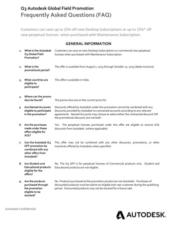
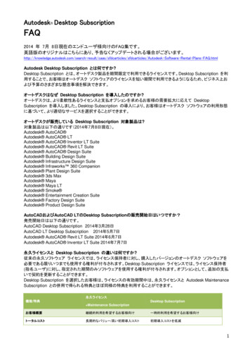
We can see that the vector artwork has been labelled withthe Part Description and Cabinet ID Number data fromwithin the ArtCamFrame CNCList text file that we chosefor this project. These labels allow the machine operator toquickly determine the purpose of each of the panels within asheet.4. Click on the Toolpaths tabToolpaths Home page.to display the5. Click on the Simulate All Toolpaths buttonin theToolpath Simulation area of the page to simulate all ofthe toolpaths associated with the vector artwork drawn onthe active sheet.The simulated toolpaths appear in the 3D View window asshown:ArtCAM CabinetmakerTutorial – Using ArtCAM Cabinetmaker 17
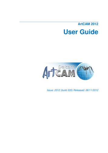
The toolpaths associated with the 3/4 Finish Ply Sheet1layer are 3/4 Finish Ply Sheet1 Profile (Panel 0P7500), 3/4Finish Ply Sheet1 Area Clear (Rout), 3/4 FinishPly Sheet1 Area Clear (RoutBack) and 3/4 FinishPly Sheet1 Drilling (DrillShelf).6. From the Main menu bar, click on the 2D View Sheets Sheet Report menu option to display a sheet report forthe 3/4 Finish Ply Sheet1 sheet in a new window.This report contains a preview of the vector artworkassociated with the sheet, data concerning the sheetdimensions and toolpath data associated with the sheet. Thereport can be saved or sent to any printer installed on yourcomputer.The sheet report for the 3/4 Finish Ply Sheet1 sheet appearsas follows:18 Tutorial – Using ArtCAM CabinetmakerArtCAM Cabinetmaker
7. Click on the Reset Simulation buttonto delete thesimulated toolpaths currently shown in the 3D Viewwindow.8. Repeat these steps for each of the sheets within the model.Previewing the LabelsFinally, we will preview the labels generated for each of the panelsthat make up our cabinet project.1. Using Windows Explorer, navigate to whichever folder youhave defined in the Select Gcode Folder area as thelocation for the toolpath output files generated by ArtCAMCabinetmaker.2. Double-click your mouse on this folder to view its contents.3. Right-click on the labels.csv file to display its context menu,move the mouse cursor over the Open With menu option,and then select the Notepad option to view the contents ofthe file:ArtCAM CabinetmakerTutorial – Using ArtCAM Cabinetmaker 19
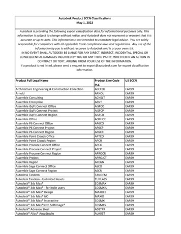
If you do not have Notepad installed, you can use WordPad,Microsoft Excel or any other suitable text-editing toolcurrently installed on your computer to open the file.We can see that each line of text within the file comprises ofvalues associated with the following fields:Material ArtCAM Sheet, Part Description,Cabinet ID NumberThis file can be used to print labels for each of thecomponents in your cabinet project. For example, whenopening the labels.csv file using the Avery Wizard forMicrosoft Word 2000 along with its L4737 RemovableLabels template, the data within the file is formatted asfollows:20 Tutorial – Using ArtCAM CabinetmakerArtCAM Cabinetmaker
Delcam plc do not recommend any particular third-partylabelling software for use in conjunction with the labels.csvfile generated by ArtCAM Cabinetmaker. For furtherinformation, please consult with your software reseller.ArtCAM CabinetmakerTutorial – Using ArtCAM Cabinetmaker 21
22 Tutorial – Using ArtCAM CabinetmakerArtCAM Cabinetmaker
Reference MaterialAssociated File TypesThere are four common file types associated with ArtCAMCabinetmaker: CSV, TXT, DXF and TPL. The following informationoffers an explanation of each of these file types.What are CSV Files?CSV (Comma Separated Variable) files are a traditional means ofwriting database or spreadsheet files to
in ArtCAM that are defined in terms of their geometric shape, such as arcs, squares or circles. This type of image is most suited to technical drawings or designs that require precise geometry and sizing. ArtCAM Cabinetmaker can import DXF layered panel data previously exported from third party design software as 2D vector artwork, which