Transcription
VT650/VT900Gas Flow AnalyzerUsers Manual FBC - 0099October 2017, Rev. 1 2017 Fluke Corporation. All rights reserved. All product names are trademarks of their respective companies.
Warranty and Product SupportFluke Biomedical warrants this instrument against defects in materials and workmanship for one year from the date of original purchase OR twoyears if at the end of your first year you send the instrument to a Fluke Biomedical service center for calibration. You will be charged ourcustomary fee for such calibration. During the warranty period, we will repair or at our option replace, at no charge, a product that proves to bedefective, provided you return the product, shipping prepaid, to Fluke Biomedical. This warranty covers the original purchaser only and is nottransferable. The warranty does not apply if the product has been damaged by accident or misuse or has been serviced or modified by anyoneother than an authorized Fluke Biomedical service facility. NO OTHER WARRANTIES, SUCH AS FITNESS FOR A PARTICULAR PURPOSE,ARE EXPRESSED OR IMPLIED. FLUKE SHALL NOT BE LIABLE FOR ANY SPECIAL, INDIRECT, INCIDENTAL OR CONSEQUENTIALDAMAGES OR LOSSES, INCLUDING LOSS OF DATA, ARISING FROM ANY CAUSE OR THEORY.This warranty covers only serialized products and their accessory items that bear a distinct serial number tag. Recalibration of instruments isnot covered under the warranty.This warranty gives you specific legal rights and you may also have other rights that vary in different jurisdictions. Since some jurisdictions donot allow the exclusion or limitation of an implied warranty or of incidental or consequential damages, this limitation of liability may not apply toyou. If any provision of this warranty is held invalid or unenforceable by a court or other decision-maker of competent jurisdiction, such holdingwill not affect the validity or enforceability of any other provision.7/07
NoticesAll Rights Reserved Copyright 2017, Fluke Biomedical. No part of this publication may be reproduced, transmitted, transcribed, stored in a retrievalsystem, or translated into any language without the written permission of Fluke Biomedical.Copyright ReleaseFluke Biomedical agrees to a limited copyright release that allows you to reproduce manuals and other printed materials for use inservice training programs and other technical publications. If you would like other reproductions or distributions, submit a writtenrequest to Fluke Biomedical.Unpacking and InspectionFollow standard receiving practices upon receipt of the instrument. Check the shipping carton for damage. If damage is found, stopunpacking the instrument. Notify the carrier and ask for an agent to be present while the instrument is unpacked. There are no specialunpacking instructions, but be careful not to damage the instrument when unpacking it. Inspect the instrument for physical damagesuch as bent or broken parts, dents, or scratches.Technical SupportFor application support or answers to technical questions, either email techservices@flukebiomedical.com or call 1-800- 850-4608 or1-440-248-9300 (Europe 31-40-2965314).ClaimsOur routine method of shipment is via common carrier, FOB origin. Upon delivery, if physical damage is found, retain all packingmaterials in their original condition and contact the carrier immediately to file a claim. If the instrument is delivered in good physicalcondition but does not operate within specifications, or if there are any other problems not caused by shipping damage, please contactFluke Biomedical or your local sales representative.Returns and RepairsReturn ProcedureAll items being returned (including all warranty-claim shipments) must be sent freight-prepaid to our factory location. When you returnan instrument to Fluke Biomedical, we recommend using United Parcel Service, Federal Express, or Air Parcel Post. We alsorecommend that you insure your shipment for its actual replacement cost. Fluke Biomedical will not be responsible for lost shipments orinstruments that are received in damaged condition due to improper packaging or handling.Use the original carton and packaging material for shipment. If they are not available, we recommend the following guide forrepackaging: Use a double–walled carton of sufficient strength for the weight being shipped. Use heavy paper or cardboard to protect all instrument surfaces. Use nonabrasive material around all projecting parts. Use at least four inches of tightly packed, industry-approved, shock-absorbent material around the instrument.
Returns for partial refund/credit:Every product returned for refund/credit must be accompanied by a Return Material Authorization (RMA) number, obtained from ourOrder Entry Group at 1-440-498-2560.Repair and calibration:To find the nearest service center, go to www.flukebiomedical.com/service orIn the U.S.A. and Asia: Cleveland Calibration Lab Tel: 1-800-850-4608 x2564 Email: globalcal@flukebiomedical.comIn Europe, Middle East, and Africa: Eindhoven Calibration Lab Tel: 31-40-2675300 Email: ServiceDesk@fluke.comTo ensure the accuracy of the Product is maintained at a high level, Fluke Biomedical recommends the product be calibrated at leastonce every 12 months. Calibration must be done by qualified personnel. Contact your local Fluke Biomedical representative forcalibration.CertificationThis instrument was thoroughly tested and inspected. It was found to meet Fluke Biomedical’s manufacturing specifications when itwas shipped from the factory. Calibration measurements are traceable to the National Institute of Standards and Technology (NIST).Devices for which there are no NIST calibration standards are measured against in-house performance standards using accepted testprocedures.WARNINGUnauthorized user modifications or application beyond the published specifications may result in electrical shock hazards or improperoperation. Fluke Biomedical will not be responsible for any injuries sustained due to unauthorized equipment modifications.Restrictions and LiabilitiesInformation in this document is subject to change and does not represent a commitment by Fluke Biomedical. Changes made to theinformation in this document will be incorporated in new editions of the publication. No responsibility is assumed by Fluke Biomedicalfor the use or reliability of software or equipment that is not supplied by Fluke Biomedical, or by its affiliated dealers.Manufacturing LocationThe VT650/VT900 Gas Flow Analyzer is manufactured at Fluke Biomedical, 6920 Seaway Blvd., Everett, WA, U.S.A.
Table of ContentsTitlePageIntroduction . 1Key Features . 1Safety Information . 2Unpacking and Inspection . 5Accessories . 6The Analyzer . 8Power On the Analyzer . 10Analyzer Connections . 12Airway Flow (Inlet and Exhaust) . 12Ultra-Low Flow and - (VT900) . 13High Pressure . 13Low Pressure ( and -) . 14Ultra-Low Pressure (VT900 only) . 14Test Setup . 15Bi-directional Flow Mode . 15i
VT650/VT900Users ManualUnidirectional Flow Mode . 16Inspiratory Flow Connections . 16Expiratory Test Connections . 17Operations . 18Measured Signals . 18Airway Flow . 19Airway Pressure . 19Airway Temperature and Humidity . 19High Pressure . 19Low Pressure . 20Ultra-Low Pressure (VT900) . 20Ultra-Low Flow (VT900) . 20Barometric Pressure . 20Oxygen Concentration . 21Calculated Breath Parameters . 21Excel Add-in . 21Measurements . 22Make a Measurement . 22Save a Measurement . 22Main Menu Functions . 24Profiles Menu . 24Setup Menu . 25Units . 31Special Tests Menu . 32Calibrate Oxygen . 33Customize Breath Views . 34ii
Contents (continued)Memory Menu . 34Test ID . 34Maintenance, Service and Calibration . 35Cleaning . 35Oxygen Sensor Replacement . 36Battery Status . 36Battery Replacement . 37Replaceable Parts . 38Service and Calibration . 38Specifications . 39Pressure . 40Flow . 41iii
VT650/VT900Users Manualiv
IntroductionKey FeaturesThe VT650/VT900 Gas Flow Analyzer (theAnalyzer or Product), is a general purpose gasflow analyzer with special features for testingmechanical patient ventilators. The Analyzermeasures bi-directional air flow, high anddifferential low pressure, barometric pressure,Oxygen concentration and airway pressure,airway temperature and airway humidity. TheVT900 also measures ultra-low flow ( 750 ml/min) and ultra-low pressure (0 mbar to 10 mbar).The Analyzer can be controlled externally usingUSB commands or automated with availablesoftware. The Analyzer operates on arechargeable Li-Ion battery or external powersupply for stationary or portable use. All figuresshow the VT900 unless otherwise noted. Full range, bi-directional air flow and volumechannel Ultra-low flow and pressure ranges (VT900) High pressure, vacuum and differential lowpressure Airway pressure, Oxygen concentration,temperature, and humidity Barometric pressure External trigger input (VT900) Rechargeable Li-ion battery with up to8 hours battery life USB port Customizable profiles that can be saved Numerical and graphical screens with realtime data Automation software available On-board memory1
VT650/VT900Users ManualSafety Information Disable the Product if it is damaged.A Warning identifies conditions and actions thatpose hazards to the user; a Caution identifiesconditions and actions that may damage theProduct or the equipment under test. Do not use the Product if it isdamaged.XW Warning Read all safety information beforeyou use the Product. Recharge the battery when the lowbattery indicator shows to preventincorrect measurements. Lowbattery will also corrupt the memorycard. Use the Product only as specified, orthe protection supplied by theProduct can be compromised. Remove all probes, test leads, andaccessories before the battery dooris opened. Carefully read all instructions. Remove all probes, test leads, andaccessories that are not necessaryfor the measurement.To prevent possible electrical shock, fire,or personal injury: Do not use the Product aroundexplosive gas, vapor, or in damp orwet environments.2 The battery door must be closed andlocked before you operate theProduct. Use this Product indoors only. Use only specified replacementparts. Do not use the Product if it operatesincorrectly. Have an approved technician repairthe Product.
Gas Flow AnalyzerSafety Information Batteries contain hazardouschemicals that can cause burns orexplode. If exposure to chemicalsoccurs, clean with water and getmedical aid. Do not disassemble the battery. Repair the Product before use if thebattery leaks. Use only Fluke approved poweradapters to charge the battery. Remove the battery if the Product isnot used for an extended period oftime, or if stored in temperatures 50 C. If the battery is not removed,battery leakage can damage theProduct.W CautionTo prevent possible damage, removethe O2 sensor if the Product is storedin temperatures 50 C. Do not short the battery terminalstogether. Do not disassemble or crush batterycells and battery packs. Do not keep cells or batteries in acontainer where the terminals canbe shorted. Do not put battery cells and batterypacks near heat or fire. Do not put insunlight.3
VT650/VT900Users ManualSymbols used on the Analyzer and in this manual are explained in Table 1.Table 1. SymbolsSymbolSymbolMeaningWWARNING. RISK OF DANGER.XWARNING. HAZARDOUS VOLTAGE.Risk of electric shock. Consult user documentation.PConforms to European Union directives. Power button)Conforms to relevant North AmericanSafety Standards. Li-ion Battery Conforms to relevant Australian Safetyand EMC standards."4MeaningPower input 15 V dc 2.0 A Conforms to relevant South KoreanEMC Standards. Conforms to the Appliance Efficiency Regulation (California Code of Regulations, Title 20,Sections 1601 through 1608), for small battery charging systems. This product complies with the WEEE Directive marking requirements. The affixed label indicatesthat you must not discard this electrical/electronic product in domestic household waste. ProductCategory: With reference to the equipment types in the WEEE Directive Annex I, this product isclassed as category 9 "Monitoring and Control Instrumentation" product. Do not dispose of thisproduct as unsorted municipal waste.
Gas Flow AnalyzerUnpacking and InspectionUnpacking and InspectionMake sure you do not damage the Analyzer asyou unpack. Inspect the shipping carton for damage. If there is no damage, remove theAnalyzer from the shipping case. Savethe box and packing materials.If the shipping carton is damaged,carefully continue to unpack theAnalyzer. Note any dents and scratcheson the Analyzer. Save the damagedshipping carton and packing material forthe carrier’s inspection. Do a visual inspection. Make sure theAnalyzer is intact. If there is any physicaldamage, such as bent or broken parts, dents,or scratches, call a Fluke Biomedical ServiceCenter immediately. To return the Analyzer toFluke Biomedical for service see Returns andRepairs. Check the standard accessories. If anyaccessories are missing, contact a FlukeBiomedical Service Center.5
VT650/VT900Users ManualAccessoriesTable 2 is a list of the standard accessories provided with the Analyzer.Table 2. Standard AccessoriesItemPart NumberUSB Serial cable4015274AC power adapter4760480Accessory kit with:49221156Bacterial filter for external connection to the flow ports (1)21337121.2 m (4 ft) silicon tubing (2)223717222 mm ID x 22 mm ID tubing adapters (2)213330522 mm OD x 22 mm OD tubing adapters (2)2133291Tapered 15 mm OD x 22 mm OD tubing adapters (2)2133269DISS Handtight Nut/Nipple to 6.4 mm (1/4 in) ID hose barb adapter (1)2216329Certificate of Calibration with test data--
Gas Flow AnalyzerAccessoriesTable 3 is a list of optional accessories.Table 3. Optional AccessoriesItemPart NumberSoft-sided carrying case for ACCU-LUNG2397628ACCU LUNG II test lung4281291ACCU-LUNG Lung Simulator with Soft-sided carryingcase (2397628)2387318VESA system mount49696577
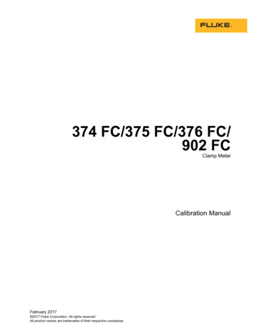
VT650/VT900Users ManualThe AnalyzerFigure 1 shows the top of the Analyzer.1VT900GAS FLOW ANALYZER23FLOWINLETlpmFLOWEXHAUST 300750 ml /minULTRALOW FLOW870 TO 10 mbar0.8 TO 10 barULTRALOW PRESSUREHIGHPRESSURE65160 mbarLOWPRESSURE4Figure 1. Top of the Analyzer8 DEFGHTouchsceen LCDFlow exhaustFlow inletLow pressure and High pressure and vacuumUltra-low pressure (VT900)Ultra-low flow and - (VT900)Power button
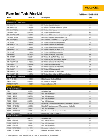
Gas Flow AnalyzerThe AnalyzerFigure 2 shows the back of the Analyzer.211O2 SENSOR ACCESS DOOR6543Figure 2. Back of the Analyzer Handle clip USB port Oxygen sensor doorD External trigger input (VT900)E Battery status indicatorF External DC power input9
VT650/VT900Users ManualFigure 3 shows the bottom of the Analyzer. VESA mount points (FDMI MIS-C, fits WxH12of 75 mm x 35 mm)3 Oxygen sensor door screw BailD Battery door screwsE Battery doorPower On the AnalyzerTo power on the Analyzer, push .The Analyzer defaults to the Airway screen.Figure 4 shows the main screen of the Analyzer.54Figure 3. Bottom of the Analyzer10
Gas Flow AnalyzerThe AnalyzerTo make a selection, tap the screen.234156Figure 4. Example of Airway Measurement Measurement and Other Menus Selected Profile Measurement settingsD Battery symbolE Display areaF Screen options11
VT650/VT900Users ManualAnalyzer ConnectionsYou can connect the Analyzer to a ventilator andtest lung in either a bi-directional orunidirectional flow configuration.Airway Flow (Inlet and Exhaust)The outer diameter of the airway port is astandard 22 mm fitting for use with patienthoses. The inner diameter of the airway portaccepts a 15 mm male respiratory fitting for usewith endotracheal tubes, gas sampling adapters,and similar equipment.WCautionTo avoid damage to the Analyzer andavoid adverse affects on the Analyzerperformance: Do not put metal objects intoconnectors.12 Always use the external flow filter onthe main airflow channel inlet. Thishelps reduce turbulence and keepsout small particles that coulddamage the flow sensor. To avoid damage to the sensor,make sure the pressure inside theairway port does not exceed 5 psi. Measure only dry gases with theairway port. Do not use this port tomeasure humidified gases.
Gas Flow AnalyzerThe AnalyzerUltra-Low Flow and - (VT900)High PressureThe and - ultra-low-flow ports have a barbedhose fitting connection.The high-pressure port is primarily to test walland tank pressurized gas sources. Theconnector works with standard oxygen DISSfittings, as used on oxygen supply hoses.WCautionTo avoid damage to the Analyzer andavoid adverse affects on the Analyzerperformance: To avoid damage to the sensor,make sure the pressure inside theultra-low-flow port does not exceed25 psi. Measure only dry gases with theultra-low-flow port. Do not use thisport to measure humidified gases.WCautionTo avoid damage to the Analyzer andavoid adverse affects on the Analyzerperformance: To avoid damage to the sensor,make sure applied pressure doesnot exceed 188 psi (13 bar). Measure only dry gases with thehigh-pressure port. Do not use thisport to measure fluid pressure.13
VT650/VT900Users ManualLow Pressure ( and -)Ultra-Low Pressure (VT900 only)Measure differential low pressure between the and - ports or gauge pressure on either port.Connectors are barbed hose fittings.The ultra-low pressure port has a barbed hosefitting connection.WCautionTo avoid damage to the Analyzer andavoid adverse affects on the Analyzerperformance: To avoid damage to the sensor,make sure applied pressure doesnot exceed 5 psi. Measure only dry gases with thelow-pressure port. Do not use thisport to measure fluid pressure.14WCautionTo avoid damage to the Analyzer andavoid adverse affects on the Analyzerperformance: To avoid damage to the sensor,make sure applied pressure doesnot exceed 5 psi. Measure only dry gases with theultra-low-pressure port. Do not usethis port to measure fluid pressure.
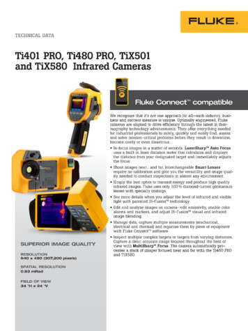
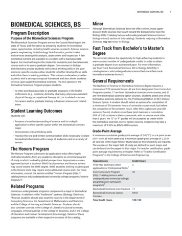
Gas Flow AnalyzerTest SetupTest SetupBi-directional Flow ModeUse the airway port for ventilator testing. Use atest lung to set up a test that measures ventilatorparameters in bi-directional or uni-directionalmodes. Fluke Biomedical recommends the bidirectional mode.For bi-directional flow connections, see Figure 5.1. Use a Y-piece adapter to connect theventilator to the flow inlet on the Analyzer.2. Use a standard breathing hose to connect tothe exhaust port on the Analyzer.The Analyzer shows the flow of gasdelivered by the ventilator.ExhaustInletTest LungGAS FLOW ANALYZERVentilatorVT900Inspiratory HoseFLOWINLETFLOWEXHAUST 300 lpm750 ml /min0 TO 10 mbar0.8 TO 10 barULTRALOW FLOWULTRALOW PRESSUREHIGHPRESSURE160 mbarLOWPRESSUREExpiratory HoseFigure 5. Bi-Direction Flow Mode Connections15
VT650/VT900Users ManualUnidirectional Flow ModeInspiratory Flow ConnectionsUse the unidirectional flow to measure eitherinspiratory or expiratory gas flow.For inspiratory connections, see Figure 6.1. Connect the inspiratory hose to the flow inleton the Analyzer.2. Use a standard breathing hose to connectthe test lung to the exhaust port on theAnalyzer.InletExhaustInspiratory HoseVT900GAS FLOW ANALYZERFLOWINLETFLOWEXHAUSTTest Lung750 ml /min0 TO 10 mbar0.8 TO 10 barULTRALOW FLOWULTRALOW PRESSUREHIGHPRESSURE160 mbarLOWPRESSUREExpiratory HoseFigure 6. Inspiratory Breathing Circuit Connections16Ventilator 300 lpm
Gas Flow AnalyzerTest SetupExpiratory Test Connections2. Use a standard breathing hose to connectthe ventilator to the exhaust port on theAnalyzer.For expiratory connections, see Figure 7.1. Connect the expiratory hose from the testlung to the flow inlet on the Analyzer.The Analyzer shows the flow of gasdelivered by the ventilator.InletExhaustTest LungVT900GAS FLOW ANALYZERFLOWINLETFLOWEXHAUSTVentilatorInspiratory Hose 300 lpmExpiratory Hose750 ml /min0 TO 10 mbar0.8 TO 10 barULTRALOW FLOWULTRALOW PRESSUREHIGHPRESSURE160 mbarLOWPRESSUREFigure 7. Expiratory Breathing Circuit Connections17
VT650/VT900Users ManualOperationsMeasured SignalsUse the Analyzer to measure flow and pressure.For each test: select the test and do the setup.The Analyzer measures these signals:Displayed options depend on the selected test: Airway pressure Zero—Corrects sensor offsets for theselected measurements. Airway temperature and humidity Graph—Select the parameters to graph. Back—Return to the previous screen. Clear—Clear the graph and statistics(minimum, maximum, and average). Airway flow High pressure Low pressure Ultra-low pressure (VT900) Ultra-low flow (VT900) Autoscale—Toggles between Autoscale andmanual scale. Barometric pressure Profiles—Select a different profile. Calculated breath parameters Save—Saves the final result.18 Oxygen concentration
Gas Flow AnalyzerOperationsAirway FlowAirway Temperature and HumidityThe Analyzer has a full-range flow ( 300 lpm),with bi-directional flow measurement. Flowmeasurements are either static flows—nobreath variations, or ventilator waveforms—bothan expiratory phase and an inspiratory phase.The Analyzer uses a heat transfer sensor tomeasure the flow.There is a temperature / humidity sensor in theairway channel on the exhaust side of the flowsensor. The Analyzer uses the temperaturereading to automatically adjust for the gascorrections (see Table 6).Use this measurement for pediatric or adultventilators or to determine the performance ofmany types of flow meters.High PressureAirway PressureThe Analyzer measures airway pressure from aproximal tap of the channel (near the exhaustport).Tap More Data on the Airway screen to seetemperature and humidity.The high-pressure port measures gaugepressure in the range of -0.8 bar to 10 bar. TheAnalyzer can use this pressure measurement forany gauge pressure in the given range.19
VT650/VT900Users ManualLow PressureUltra-Low Flow (VT900)The low-pressure port is a dual-port connectionconsisting of a ( ) positive and a (-) negativepressure port.The Analyzer (VT900 only) has ultra-low flow( 750 ml/min) bi-directional flow measurementcapability. The flow measurement is foraccurate, high resolution, static low flowmeasurements, not for ventilator waveforms.The flow sensor uses the heat transfer methodto measure air flow. Use the ultra-low flow tomeasure many types of low flow meters.The differential pressure range is 160 mbar.Use this pressure measurement for anypressure differential or gauge pressure in thegiven range.Ultra-Low Pressure (VT900)The ultra-low pressure sensor measures gaugepressure in the range of 0 mbar to 10 mbar. Usethis pressure range for accurate, very lowpressure measurements.20Barometric PressureThe Analyzer makes barometric pressuremeasurements. The barometer reads absolutepressures from 8 psia to 18 psia. The Analyzeralso uses the barometer in the automatic gascorrections for airway flow measurements.
Gas Flow AnalyzerOperationsOxygen ConcentrationCalculated Breath ParametersThe Analyzer measures oxygen concentrationthrough the airflow channel. An integratedsensor measures the oxygen percent of the gasin the airflow channel of the Analyzer. The rangefor this sensor is 0 % to 100 %. The oxygen cellis mounted inside the enclosure on the rearbulkhead for the high-flow circuit. The oxygencell must be replaced approximately once a year(VT650) or every 2 years (VT900).From the primary flow and pressuremeasurements, the Analyzer calculates breathparameters. A breath detection algorithmdetermines the various phases of a ventilatorbreath and calculates the parameters listed inTable 10.Excel Add-inInstall custom Excel add-in, available fordownload at www.flukebiomedical.com. Use theExcel Add-in on a PC to view results data. TheExcel Add-in has these worksheets: Data – shows saved data Recording – shows recorded data Graph – shows graphs and data21
VT650/VT900Users ManualMeasurementsSave a MeasurementFigure 8 is an example of the measurementscreen.The Analyzer can save readings or start arecording to save.Make a MeasurementTo save a measurement:To make a measurement:1. On the measurement screen, tap Save.1. Select the type of measurement.2. Select the type of reading you want to save.2. To set the offset to zero, tap Zero. Makesure to remove all the connections.NoteYou may need to block the airflow channelif room air currents are present.3. To switch between Auto and manual scaling,tap Autoscale.22 Data—The current data points. Graph—The current data points in agraphical format. Record—Set up the parameters andstart a new recording to save.
Gas Flow AnalyzerOperations12234Figure 8. Example of Measurement Measurements Change scaling Graph areaD Toggle manual or automatic scaling23
VT650/VT900Users ManualMain Menu FunctionsProfiles MenuUse the Main menu to access the Analyzerfunctions, including:You can configure the settings on the Analyzerto create test profiles. The analyzer can save upto 20 profiles. Profiles Setup Units Special Tests Memory Customize Breath Views Calibrate Oxygen Test IDThe Analyzer stores the profiles using a numericcode and a profile name. 00 is the defaultnumeric code. You cannot change the 00 defaultprofile. An asterisk (*) indicates the profile thatwill be loaded at start up.To select a profile, use the arrow keys.To manage profiles, select Menus Profile ortap Profile on the Airway screen.Options are: View Current —View the settings for thecurrent profile loaded on the Analyzer. TapMore for another page of settings. View Selection—View the settings of thehighlighted profile in the profile list. Tap Morefor another page of settings.24
Gas Flow AnalyzerOperations *Use on Power-Up—Make the selectedprofile the default profile.Setup Menu Back—Go to the main Profile menu.Use the Setup menu to make and view theAnalyzer settings. Edit Name—Change the name of theselected profile.To setup the Analyzer, select Menus Setup. Load—Select a profile to load. If there are nosaved profiles, the option is Default.For Setup selections, see T
for the use or reliability of software or equipment that is not supplied by Fluke Biomedical, or by its affiliated dealers. Manufacturing Location The VT650/VT900 Gas Flow Analyzer is manufactured at Fluke Biomedical, 6920 Seaway Blvd., Everett, WA, U.S.A. In the U.S.A. and Asia: Cleveland Calibration Lab Tel: 1-800-850-4608 x2564