Transcription
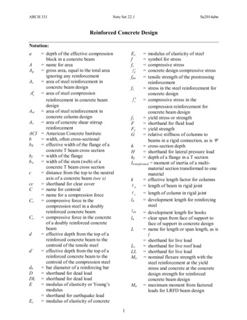
87WATERPROOFING OF REINFORCEDCONCRETE FLAT ROOF12
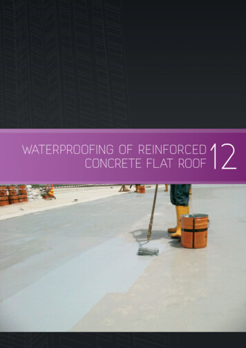
88 GOOD INDUSTRY PRACTICES12 WATERPROOFING OF REINFORCEDCONCRETE FLAT ROOF12.1 BACKGROUND12.2 DESIGN AND CONSTRUCTION OF FLAT ROOFMost roofs in Singapore are constructedThe proper design of falls in a flat roof is an essential consideration in the overallusing reinforced concrete which isdrainage of the roof. Falls create flow paths to direct the drainage of rain-water awayknown to have pores or capillary tracts.from the roof to suitable discharge points. To be effective, it is essential to clearDepending on the designed strength,surface water as rapidly as possible from the flat roof to avoid ponding or stagnationdensity and installation techniques, theof water on the roof itself.number of pores can vary. These poresare interconnected within the concreteWaterponding on a flat roof is a prime cause of deterioration because variations inand water will penetrate through suchtemperature between wet and dry areas of the roof can cause differential thermalcapillary tracts aided by osmotic effect.movement. Together with the accumulation of acids left by evaporating rain, thiswould cause a breakdown on the roof surface. In general, a minimum fall of 1 in 80 willConcrete is known to be inherently weakhelp to prevent ponding of water.in tension; cracks and voids can also formdue to thermal expansion, contractionDuring construction, precautions must be taken to prevent excessive moisture fromand shrinkage. As a result, water willbeing trapped between the reinforced concrete roof structure and membrane. Thisseep through these voids. Therefore,is one of the common causes of flat roof waterproofing failure. Large amount ofwaterproofing is required to keep thewater vapour can evaporate from reinforced concrete or a wet screed. Once theroof water-tight since they are exposedwaterproofing membrane is laid, drying out of the structural slab will mostly taketo the weather.place from the underside of the deck. Cross ventilation beneath the deck is usuallyquite restricted due to erected partition walls. Any trapped moisture subjected toincreased temperature from the sun will form vapour which will exert itself directlybeneath the waterproofing membrane. If this vapour pressure is not released orvented sufficiently, the build-up pressure will begin to form a blister on the membraneitself and residual dampness on the underside of the roof. When the waterproofingmembrane has suffered an irreversible stretch, subsequent cooling will not cause theair pocket to return to its original size. Therefore, if a dry surface cannot be achievedwithin a reasonable period of time, direct membrane adhesion should be postponedor an alternative method of laying should be considered.12.3 ROOF MEMBRANE SYSTEMSThe waterproofing membrane is considered to be most important component of theroofing system as it serves the main function of keeping water out of the building.Below are some common roof waterproofing membranes used locally:a. Liquid-applied membranesLiquid-applied membranes are applied on site in a liquid form which is allowed toset and form into a water impermeable membrane. Bituminous-based (except thosecontaining coal tar) and polymeric-based membranes can be applied when they arecold while those containing coal tar are usually applied when heated.Liquid-applied membranes are seamless, semi-flexible, easy to apply, detail, maintainand repair. However careful supervision and control during application is needed,particularly in ensuring proper curing of concrete, consistent thickness and uniformFig. 12.1 – Application of liquid-appliedmembrane using roller.application.
89b. Pre-formed sheet membranesOne type of pre-formed membranes is the polymer-modified bitumen membranes andthey are applied by heat or attached with an adhesive. These blended or ‘modified’asphaltic product are bonded to a high strength fabric of polyester or fiberglass andproduced into rolls. They have elongation and recovery properties which make themsuitable to protect against stresses created by wind, temperature fluctuation andnormal structural expansion and contraction of the building. Some of these productsare also modified to increase their resistance to fire, thus increasing their fire-rating.Styrene-butadiene-styrene (SBS) rolls are modified with 'rubbers' and compatiblewith petroleum products. Atactic Polypropylene Polymer (APP) rolls are modified with'plasticizers' and not compatible with all petroleum-based products, grease and oils.Fig. 12.2 – Softening polymer-modified bitumen membrane by heat welding.Another type of pre-formed membrane is made of Polyvinyl Chloride (PVC). AlthoughPVC is a hard resin, it is modified with the addition of plasticisers to make it moresupple and pliable for use as roofing membranes. PVC membranes are mainlyproduced by either the calendering or extrusion process. In the calendering process,a reinforcement layer of glass fibre or polyester scrim is normally incorporated into themembrane to provide greater strength and dimensional stability. Like all thermoplasticmembranes, they turn soft when subjected to heat. Some proprietary membranesare formulated with heat reflective compounds capable of lowering the surfacetemperature of the roof membrane by as much as 15%.Fig. 12.3 – Using hot air torch to weld the joint of PVC membranes.
90 GOOD INDUSTRY PRACTICES12.4 GOOD DETAILING PRACTICES FOR LIQUIDAPPLIED MEMBRANESAs liquid-applied membranes are not very elastic and do not bridge over cracks andWATERPROOFMEMBRANEBITUMENMEMBRANEgaps well, it is good practice to fix a lax bitumen membrane over building’s expansionand movement joints.EXPANSIONJOINTCONCRETE12.5 GOOD DETAILING PRACTICES FOR PRE-FORMEDMEMBRANES Along roof edges and parapets, corners and pipe penetrations, a minimum 25 mmFig. 12.4 – Typical example of fixingbitumen membrane over building’sexpansion and movement joint.chamfer or fillet should be provided to ensure a smooth contour for easy installationof the membrane. This fillet helps to reduce the bending stresses in the membraneas compared to bending it at 90 without the fillet.Fig. 12.5 – 25 mm fillets along parapet wall for bitumen and PVC membrane. Along edges, upstands, and vent pipe penetrations, the bitumen membrane isnormally extended at least 150 mm above the finished roof level and doubly wrappedwith appropriate overlapping at corners. It is good practice to form a groove on theparapet wall so that the edge of the bitumen membrane can be “tucked” into thegroove. With the groove on the parapet wall and the membrane ending in a horizontalposition, it can prevent water, flowing down the wall surface, from seeping through aweakened joint between the membrane and wall surface.Fig. 12.6 – Groove along parapet wall to tuck At around corners of parapet walls, the bitumen membrane should be neatly foldedand overlapped. The vertical joint at the corner should be sealed off with bitumen toprevent water seeping through any weakened joint.Fig. 12.7 – Overlapping and sealing at corner.in edge of membrane.
91 For rain-water down-pipe penetrations, before laying the horizontal bitumenmembrane, an additional small piece of membrane should be stuck to the insideof the pipe penetration while the top is cut and laid horzontal. Both top andbottom portion should be 50 mm from roof surface. As the joint around the pipepenetration is the weakest area and the horizontal membrane cannot simply justbend 90 into the pipe penetration, the additional piece of membrane acts as adownturn covering the pipe/slab joint.Fig. 12.8 – Wrapping around pipe penetration.Fig. 12.9 – After laying the horizontalmembrane around pipe penetration. For PVC membrane terminating at the parapet wall, a special PVC coated metalstrip can be used. First a small groove line can be cut on the parapet wall, then theL-shaped metal strip can be nailed on to the wall. Finally, the PVC membrane can beheat welded on to the metal strip.Fig. 12.10 – PVC coated strips for perimeter terminations.
92 GOOD INDUSTRY PRACTICES All internal and external cornersshould be further reinforced withprefabricated corner pieces usuallymadefromunreinforcedPVCmembranes to allow for greaterflexibility and workability.Fig. 12.11 – Prefabricated corner pieces for internal and external corners. For upturn at pipe penetrations, it isgood practice to use an extra piece ofPVC membrane to ‘bridge’ betweenthe horizontal and vertical membranein order to prevent water seepage atthe weak pipe/slab joint.Fig. 12.12 – PVC coated strips for perimeter terminations.12.6 SUMMARYProper design of falls in reinforced concrete flat roofs is most important in creatingflow paths to suitable discharge points. For a roof to be effective, surface water shouldbe discharged quickly without ponding or stagnation. Next, it is important to selectthe appropriate waterproofing membrane. As the roof is constantly exposed to directsunlight and rain, it is likely to experience tremendous thermal stresses that will affectits physical properties and performance. Pre-formed waterproofing membranesgenerally will perform better than liquid applied membrane as it can bridge over cracksand gaps better. Also, as they are more resistant to indentations caused by traffic, theyare suited for large flat roofs areas exposed to foot traffic. However, liquid-appliedmembrane is still preferred for small roofs and roofs with a lot of obstructions.
Also, as they are more resistant to indentations caused by traffic, they are suited for large flat roofs areas exposed to foot traffic. However, liquid-applied membrane is still preferred for small roofs and roofs with a lot of obstructions. Title: untitled Created Date: