Transcription
System 920 PFT for T1Master Reference GuideCovering Installation, Configuration,and Operation TopicsIssue 2 of this guide covers System 920 softwareversion 1.02 and later. Contact Gordon Kapes, Inc.Technical Support for further information.Gordon Kapes, Inc.5520 West Touhy AvenueSkokie, Illinois 60077 U.S.A.Telephone 847 676-1750Fax 847 982-0747www.gkinc.com40630, Issue 2October 1995
NO WARRANTIES OF ANY NATURE ARE EXTENDED BY THEDOCUMENT. Gordon Kapes, Inc. cannot accept any financial or otherresponsibility that may be the result of your use of the information inthis document or software material, including direct, indirect, special,or consequential damages.The information contained herein is subject to change without notice.Revisions may be issued to advise of such changes and/or additions.The statement below is included in this document to comply with aFederal Communications Commission (FCC) regulation. The FCC isan agency of the United States government; thus, the statement belowapplies to computing equipment installed in the United States of America.Gordon Kapes, Inc. is taking appropriate steps to be in compliance withFCC regulations and similar regulations of other countries.WARNING: This equipment generates, uses, and can radiate radiofrequency energy and, if not installed and used in accordance with theinstruction manual, may cause interference to radio communications.It has been tested and found to comply with the limits for a Class Acomputing device pursuant to Subpart J of Part 15 of FCC Rules, whichare designed to provide reasonable protection against such interferencewhen operated in a commercial environment. Operation of this equipmentin a residential area is likely to cause interference, in which case the userat his own expense will be required to take whatever measure may berequired to correct the interference. 1993, 1994, 1995 Gordon Kapes, Inc. All rights reserved.Printed in the United States of AmericaAll product names mentioned in this manual are trademarked orcopyrighted by their respective manufacturers.
ContentsContentsForewordPart IIntroductionChapter OneUnderstanding the System 920The System 920 PFT for T1 . 1-1System 920 Resources & Hardware . 1-4System 920 Monitoring Functions . 1-10Software Configuration Ensures Flexibility . 1-11Menu System Ensures Easy Status Review. 1-13Viewing Operating Status . 1-14Configurable Security and Other Features of the System 920 . 1-16Part IIPlanning For and Installing the System 920Chapter TwoPlanning for the System 920Overview . 2-1Selecting Mounting Location . 2-1Selecting –48Vdc Power Source . 2-2Obtaining Analog Telephone Sets . 2-2Obtaining 25-Pair Cables & Interconnecting Assemblies . 2-3Selecting Contacts to Monitor . 2-3Planning for Relay Contacts . 2-4Preparing Network-T1 and CPE-T1 Terminating Jacks . 2-4Obtaining or Preparing a Cable for the Maintenance Port . 2-5Obtaining a VT100 Terminal . 2-5Chapter ThreeInstalling the System 920Overview . 3-1Words of Caution. 3-1Step One: Open Carton, Check for Damage, & Locate Installation Kit . 3-2Step Two: Mount the System 920 . 3-4Step Three: Make Plug-P2 Connections . 3-5Step Four: Make Plug-P1 Connections . 3-10Step Five: Connect to the Network-T1 & CPE-T1 Circuits . 3-13Step Six: Connect to the Maintenance Port . 3-16Step Seven: Review the Installation . 3-18System 920 Master Reference Guide Issue 2 October 1995iii
ContentsPart III Configuring the System 920Chapter FourGetting Started with the Menu SystemOverview . 4-1Conventions . 4-2Accessing the Menu System . 4-4Exiting the Menu System and Disconnecting. 4-6Selecting Menu Options . 4-6Using Online Help . 4-7Chapter FivePerforming General System ConfigurationOverview . 5-1Chapter SixConfiguring the T1/DS1 Interface CardOverview . 6-1Procedure for Setting General Parameters . 6-13Procedure for Setting Channel Parameters . 6-15Chapter SevenConfiguring OPS CardsOverview . 7-1Chapter EightConfiguring ACD FunctionsOverview . 8-1Chapter NineConfiguring Redirect DialingOverview . 9-1Chapter TenConfiguring DNIS FunctionsOverview . 10-1Procedure for Setting DNIS Routing Configuration Parameters . 10-9Chapter ElevenConfiguring Recorder/AnnouncerParametersOverview .11-1Chapter TwelveConfiguring System SecurityOverview . 12-1Part IV Operating the System 920Chapter ThirteenViewing General System StatusOverview . 13-1Chapter FourteenViewing ACD Function StatusOverview . 14-1ivSystem 920 Master Reference Guide Issue 2 October 1995
ContentsChapter FifteenViewing Redirect Dialing StatusOverview . 15-1Chapter SixteenViewing T1/DS1 Interface Card StatusOverview . 16-1Chapter SeventeenViewing OPS Card StatusOverview . 17-1Chapter EighteenViewing Recorder/Announcer StatusOverview . 18-1Chapter NineteenUnderstanding and Using OPS ExtensionsRequired Equipment . 19-1Purpose and Use of OPS Extensions . 19-1OPS Extension Numbering . 19-2Call Progress Tones and the Alert Tone . 19-3Switch-Hook Flash Capabilities . 19-4Part V Testing, Maintaining, and Troubleshooting the System 920Chapter TwentyPlaying and Recording Recorder/AnnouncerMessagesOverview . 20-1Recording a Message . 20-3Playing a Message . 20-5Chapter Twenty-OneUsing System DiagnosticsOverview . 21-1Viewing ST-Bus Data . 21-1Viewing T1/DS1 Signal Timing Data . 21-11Viewing Tone Receiver Information . 21-15Viewing Detailed System Status . 21-18Connecting Tones to OPS Ports and T1/DS1 Channels . 21-22Seizing the Network T1 with the Network Transfer Relay . 21-28Resetting System 920 Components . 21-31Viewing Memory Contents. 21-34Chapter Twenty-TwoPerforming Maintenance & Testing TasksUsing the Menu SystemOverview . 22-1System 920 Master Reference Guide Issue 2 October 1995v
ContentsChapter Twenty-Three Maintaining the System 920 & Associated SiteOverview . 23-1Check Power Switch and Status LEDs . 23-2Check OPS Extensions . 23-4Check Contact Connections . 23-4Check Synchronization with Network T1 . 23-4Verifying UPS Power Supply . 23-5Review System Configuration . 23-5Ensure Documentation is Available . 23-5Review Disaster-Recovery Training Plan . 23-6Call Factory for Updates. 23-6AppendicesAppendix AConfiguration WorksheetsAppendix BTechnical NotesAppendix CSystem 920 SpecificationsAppendix DTerminal Emulator RequirementsAppendix EMaintenance Port ConnectionsAppendix FFCC RequirementsIndexviSystem 920 Master Reference Guide Issue 2 October 1995
ForewordForewordA Welcome from Gordon KapesI’m proud to welcome you to the latest product from Gordon Kapes, Inc.The System 920 is the culmination of everything I’ve learned about powerfailure transfer over the past 10 or so years. I’m confident that as youbecome accustomed to the System 920, you’ll share my enthusiasm forthe power and versatility that it contains. I take a personal interest in everyproduct we make, and I feel that this one is truly outstanding.I give much credit to those people who contributed to making the System920 a reality. The software was written by Larry Leviton and Steve Malott.Circuit boards were designed by Al Lux. Mechanical design was by FredRoeck. Testing was handled by Joe Urbanczyk. The documentation waswritten by Bill Beaman, with editing and production by Barbara Govednik.Prototype hardware was built by Maxine Allbritton. Hardware was designed by Tom Dawson, with consultation from Mitch Budniak. The graphics were designed by Jim McGuire. Engineering support and personalpublishing was performed by Carrie Loving. Ben Kamen provided technical support. I did the overall product design and kept adding features untilmy presence was definitely not welcome!Field performance is the only accurate measurement of just how goodthe System 920 really is. To that end I welcome your comments, suggestions, or questions. Please call me at 847 676-1750, send a fax at847 982-0747, or visit our website at www.gkinc.com.System 920 Master Reference Guide Issue 2 October 1995vii
ForewordThis page intentionally left blank.viiiSystem 920 Master Reference Guide Issue 2 October 1995
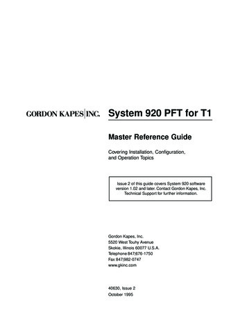
Understanding the System 920Chapter OneUnderstanding the System 920Once the sole province of telephone companies, T1 digital transmissiontechnology is now directly available to business and industry on awidespread scale. Capable of handling 24 voice conversations overtwo twisted pairs of telephone cable, T1 helps companies enhancecommunication efficiency, improve reliability, and lower costs.As organizations become more and more dependent upon T1-basedequipment, the need to implement a flexible, robust, and yet cost-effectivebackup system becomes more and more important. Gordon Kapes, Inc.believes the System 920 PFT for T1 is such a system.The System 920 PFT for T1The System 920, a completely self-contained backup phone system,extends the concept of power failure transfer (PFT) to T1 circuits. TheSystem 920 goes to work automatically when normal operation ofcustomer-premise-T1 (CPE-T1) equipment is inhibited due to a powerfailure or system malfunction.The System 920 sits between the customer-premise-T1 equipment andthe network-T1 circuit. When a failure occurs, the System 920 seizes thenetwork T1—enabling personnel at the site to continue to receive inboundcalls and continue to place outbound calls.The System 920 is a single-cabinet unit intended to be mounted on thewall of an equipment room. It combines the capabilities of a channelservice unit (CSU), a channel bank, an automatic call distributor (ACD),a two-channel recorder/announcer, and a 24-port “micro” PBX.System 920 Master Reference Guide Issue 2 October 19951-1
Understanding the System 920Figure 1-1. System 920 Installed in a Typical PBX-System Site1-2System 920 Master Reference Guide Issue 2 October 1995
Understanding the System 920Inbound-Call & Outbound-Call ConfigurationsThe System 920 provides communication for all 24 channels supplied by anetwork-T1 circuit. These can be any combination of inbound, outbound,or two-way channels.When the System 920 seizes the network T1, incoming calls can bedirected to: An analog telephone, either by way of an ACD function, a DNIS (dialednumber identification service) function, or directly—which enables thecalling party to speak with a real person. Calls received by onetelephone can easily be transferred to another telephone by usingswitch-hook flash. An outside telephone number, with or without an intermediate voicemessage—which directs the call to an alternate site A voice message—which provides the calling party with prerecordedinformation A standard reorder progress tone—which indicates to the calling partythat equipment normally used at the site is downOn-site personnel can use these analog telephones, which meet thetechnical specifications for OPS extensions, to make outgoing calls whenthe System 920 has seized the network T1. You can authorize each OPSextension for outbound access. From an authorized extension, a callercan access a network T1 channel by dialing the outbound-access digit(8 or 9).You can configure the OPS extensions to be fully functional at all times.This enables you to use them as a backup or supplementary internalphone system on a day-to-day basis—whether the network T1 has beenseized or not.System 920 Master Reference Guide Issue 2 October 19951-3
Understanding the System 920System 920 Resources & HardwareAs implied by the preceding description of its capabilities, the list of telephone backup resources provided by the System 920 is comprehensive.The following describes these resources in more detail.OPS Cards Enable Voice CommunicationsThe OPS cards enable on-premise or remotely-located analog touch-tonetelephones to serve as System 920 extensions. These extensions facilitate voice communications through the network T1 after the System 920has seized it, and they can permit internal communications on an everyday basis. As shown in Figure 1-2, the System 920 accommodates asmany as three OPS cards, with each card containing eight OPS ports.This means you can install and use as many as 24 OPS extensions witha single System 920.ACD Functions Enable Automatic Call DistributionTwo automatic-call-distributor (ACD) functions are provided by the System920. To organize and expedite incoming calls during a backup period, youcan route specific T1 channels to either ACD function. Calls routed to anACD function connect only with those OPS extensions assigned to thefunction.If all extensions assigned to the ACD function are busy, incoming calls areplaced in queue where callers either hear a recorded message or anaudible-ring progress tone until an extension becomes free. If the queue isfull, callers hear either a recorded message or a reorder progress tone(fast busy).DNIS Functions Enable Dialed Number IdentificationTwo dialed number identification service (DNIS) functions enable theSystem 920 to identify the telephone number the caller dialed. If the number is one of the DNIS match numbers you configured, you can route thecall to an OPS extension, an ACD function, a redirect function, a message, or a reorder tone.1-4System 920 Master Reference Guide Issue 2 October 1995
Understanding the System 920OPS Extensions Provide Switch-Hook Flash & Other FeaturesThe System 920 enables you to use switch-hook flash capabilities withOPS extensions. This provides a call-transfer feature that enhances theseextensions for everyday use, if desired, and extends the usefulness of theACD functions.Standard progress tones are used with OPS extensions, and an alerttone is used to warn calling parties when the system is about to reconnectCPE T1 with the network T1. You can configure the 3-digit dialing plan forOPS extensions. You also use an OPS extension to record or playmessages on the Recorder/Announcer card.Figure 1-2. System 920 Showing OPS Card 1, OPSCard 2, OPS Card 3, and Recorder/Announcer CardSystem 920 Master Reference Guide Issue 2 October 19951-5
Understanding the System 920Redirect Functions Enable Off-Site TransferIf you want to redirect incoming T1 calls to an off-site location during abackup period, you can do so—simply route the desired T1 channels toeither of two redirect functions. Each redirect function contains the telephone number for an off-site location. A call coming in on a redirectedchannel is automatically transferred to the new telephone number. If youwish, you can configure the System 920 to play one of the recordedmessages before transferring the call.Recorder/Announcer Card Stores Recorded MessagesThe Recorder/Announcer card, shown in Figure 1-2, enables you torecord two separate voice messages. Each message can be as long astwenty seconds. Either message can be played to calls coming in throughnetwork-T1 channels. Either can be played before a call is redirected toanother site. And either can be played when a call is placed in an ACDqueue or overflow. Use an OPS extension to access the card for thepurpose of recording and maintaining the messages.Relay Contact Outputs Signal External DevicesTwo relay contacts are provided by the System 920. These change statewhenever the System 920 seizes the network T1. One relay, which isnormally open, closes when the network is seized; the other, normallyclosed, opens. Once the System 920 reconnects CPE T1 to the networkT1, the relay contacts return to their normal states. You can use theserelay contacts to signal an external monitoring device that the network hasbeen seized. For example, you can use the relay contacts to signal theModel 125 Site Monitor from Gordon Kapes, Inc.1-6System 920 Master Reference Guide Issue 2 October 1995
Understanding the System 920Additional Cards Supply Operating CapabilitiesShown in Figure 1-3, the T1/DS1 Interface card interfaces the T1/DS1circuit from the network with the System 920. No external channel serviceunit (CSU) is needed when the System 920 seizes the network T1, sincethis card contains one built-in. (This CSU serves only the System 920 andis not provided for use by the CPE site.)The CPU card contains a powerful 32-bit microprocessor and logiccircuitry used for operating the System 920. Also on this card is ROMmemory used for storing program code, and battery-backed RAM memoryfor storing configuration parameters set using the menu system (describedlater in this chapter).Figure 1-3. System 920 Showing CPU Card,T1/DS1 Interface Card, and Power Supply CardSystem 920 Master Reference Guide Issue 2 October 19951-7
Understanding the System 920Finally, the Power Supply card generates operating voltages and providesthe user controls and status LEDs. These include the Manual Operationswitch, which enables you to manually seize the network T1. (Refer toFigure 1-4 for more details about the status LED panel.)ASystem 920 Power switchControls entry of –48V to the system. Move switch to the On or Offposition. Since the system cannot function without power, the switchshould be left in the On position during normal operating conditions.B 8VWhen lit, indicates 8V is being generated by the Power Supply cardand sent to other System 920 cards. This LED should always be litwhen power to the System 920 is applied and the power switch is inthe On position.C–8VWhen lit, indicates –8V is being generated by the Power Supply cardand sent to other System 920 cards. This LED should always be litwhen power to the System 920 is applied and the power switch is inthe On position.D Ring ActiveFlutters when active. This indicates ringing current is being generatedby the Power Supply card upon request of one of the OPS cards. LEDshould flutter only when ringing current is being generated. Continuousfluttering indicates a problem such as an OPS extension accidently leftoff-hook and ringing another extension.E Contact 1When lit, indicates contact-input-monitoring 1 function is enabled andin the alarm state.FContact 2When lit, indicates contact-input-monitoring 2 function is enabled andin the alarm state.G Contact 3When lit, indicates contact-input-monitoring 3 function is enabled andin the alarm state.H CPE T1 Carrier LossWhen lit, indicates CPE-T1 monitoring function is enabled and in thealarm state.INetwork T1 StatusWhen lit, is either lit steadily or flashes on and off. When lit steadily,indicates System 920 has seized the network T1 and is synchronizedwith it. When flashing on and off, indicates System 920 has seized thenetwork T1 but is not synchronized with it.When not lit, indicates the System 920 has not seized the network T1.JManual Operation switchPress and hold up to seize the network T1. Press and hold down toreconnect network T1 to CPE T1.Figure 1-4. System 920 Status LED Panel1-8System 920 Master Reference Guide Issue 2 October 1995
Understanding the System 920System 920 ConnectionsP1 and P2 are illustrated in Figure 1-5. These plugs, located on the leftand right panels of the System 920 enclosure, enable you to connect theOPS extensions, the three contact inputs, and a –48Vdc uninterruptiblepower source to the System 920. They also enable you to connect the tworelay contacts to external devices.J1, located on the left panel of the System 920, enables you to connecta terminal or personal computer to the System 920 for the purpose ofconfiguring, testing, and maintaining the unit. The terminal or personalcomputer, which does not have to be permanently installed, must beVT100 compatible.J2 enables you to connect the network-T1 circuit to the System 920.J3 enables you to connect CPE-T1 equipment to the System 920.Figure 1-5. Left and Right Panels of System 920 Showing Connection PointsSystem 920 Master Reference Guide Issue 2 October 19951-9
Understanding the System 920System 920 Monitoring FunctionsFour monitoring functions are built into the System 920. These are theCPE-T1-carrier-monitoring function and the three contact-input-monitoringfunctions. These functions, which are implemented and configured by thesite administrator, activate alarms that trigger the System 920 to seize thenetwork T1.CPE-T1 Carrier MonitoringA circuit in the System 920 monitors the carrier signal coming from theCPE-T1 equipment. When the circuit detects loss of signal for more thanone second, an alarm is activated, and the System 920 seizes the networkT1. Once the carrier signal has been reestablished for longer than onesecond, the alarm state returns to normal and the System 920 can reconnect CPE T1 to the network T1. (A system configuration parameter enables you to delay reconnection for 5, 10, or 15 minutes, or until all callshave been completed. Refer to “General System Configuration,” later inthis chapter.)Contact-Input MonitoringThe System 920 also provides three contact-input-monitoring functions.These can be connected to the alarm contacts provided by CPE-T1 equipment such as a PBX, or an ACD system. You set the normal state of eachcontact input (open or closed). When the opposite state occurs for longerthan one second, an alarm condition is activated and the System 920seizes the network T1. After the contact has returned to normal for longerthan three seconds, the system can reconnect CPE T1 and network T1.You can also seize the network T1 manually by pressing the ManualOperation switch located on the status LED panel on the front of the unit(shown in Figure 1-4). This enables you to use the System 920 at anytime. You might want to use the Manual Operation switch for a number ofdifferent reasons. You may wish to use it when there is an equipmentproblem or because you want to test the system. Or you may want to useit when administering system training or for providing communicationswhile CPE-T1 equipment is undergoing routine maintenance.1-10System 920 Master Reference Guide Issue 2 October 1995
Understanding the System 920Software Configuration Ensures FlexibilityTo meet the differing specifications required by various sites, the System920 provides a wide range of configuration possibilities. By using theSystem 920’s menu-system software, you can quickly and easily makerequired configuration settings for the following areas: General system configuration T1/DS1 channels OPS ports ACD functions DNIS functions Redirect-dialing functions Recorder/Announcer-card accessGeneral System ConfigurationGeneral system configuration consists of entering the desired OPS extension length number (3 or 4 digits), selecting the OPS operations status,selecting the connection made when you dial 0 at an OPS extension,enabling the CPE-T1-carrier-monitor and contact-input monitoring functions, and selecting the conditions under which you want the System 920to reconnect the network T1 to CPE T1 after all alarm conditions havereturned to normal.People at the site may be making calls through a network-T1 channel whenthe System 920 is ready to reconnect CPE T1 to the network T1. Sincethe system would suddenly end these conversations if it reconnectedimmediately, you can specify how reconnection is to be delayed while theconversations are being completed. You can choose to have the systemreconnect after all calls have been completed, or after a 5-, 10-, or 15minute delay if all calls have not been completed sooner. In each one ofthese cases, the system connects an alert tone every thirty seconds. Thiswarns people to end their conversations. You can also choose to have thesystem reconnect immediately without waiting for calls to be completed.System 920 Master Reference Guide Issue 2 October 19951-11
Understanding the System 920General and Individual T1/DS1-C
As organizations become more and more dependent upon T1-based equipment, the need to implement a flexible, robust, and yet cost-effective backup system becomes more and more important. Gordon Kapes, Inc. believes the System 920 PFT for T1 is such a system. The System 920 PFT for T1 The System 920, a completely self-contained backup phone system,