Transcription
2004 Owners Manual
SERVICE1. Service2. Floor Plan and Features3. Vehicle Operation4. Chinook Cube Slide RoomTM5. Automatic AirbagslJacks5. Electrical System6. Fresh Water System7. Waste Water System8. LP Gas System9. Maintenance10. Specifications11. Frequently Asked Questions
SERVICEService is important to you ., and it is equally important to us. When you buy aChinook, you can expect years of carefree service with regular but minimal maintenance. Ourreputation has been built on that premise.DOUBLE SERVICE BACKUPYour Chinook dealer's service department will promptly handle any operational difficultyyou may have with your motorhome. If such a problem is not resolved to your completesatisfaction, please take these steps:I.Discuss the problem with the general manager or owner of your dealership. Give himthe opportunity to work with his service crew in solving it.2. If the difficulty cannot be resolved to your satisfaction by your local dealer, contact theservice manager at the Chinook factory for assistance by calling:1-800-552-8886This double service backup is your best assurance that you have made the right decision inchoosing a Chinook.YOUR DEALER'S RESPONSIBILITIESYour Chinook dealer has thoroughly inspected your motorhome, resetting the lighting,plumbing, water and heating systems for any malfunctions that may have occurred duringshipment from the factory. All appliances are checked by the dealer at the time of purchase.He is obligated to explain and demonstrate the operation of your equipment and accessories,answer questions and make minor adjustments. For further instructions on operation,maintenance and warranties please refer to the individual manuals or instruction sheetsprovided in your owner's packet.-If you should require service and replacement of defective equipment, make yourrequest directly to the manufacturer of the appliance or accessory involved. In contacting anymanufacturer, dealer or Chinook factory for service or information, be sure to include all thefollowing:1. Date of purchase along with stock or vehicle identification number.2. Serial and model number and a complete description of the product.3. Detailed explanation of the difficulty you are having.Replacement parts should be purchased through the manufacturer or supplier orthrough your local dealer or supply store. If you have difficulty obtaining parts or service,contact the Chinook factory for assistance.REGISTER YOUR WARRANTY TODAY!Your first responsibility at the time of delivery is to register your warranty, so mail in yourcompleted warranty registration card today. Only by filling out and submitting your registrationcard can you be assured of the guarantees it provides. This card is for your protection as aconsumer; use it now!Rev. 1-12
SERVICERemember, warranties do not cover normal maintenance service or adjustments which maybecome necessary through normal extended use. That is why. afteruiy have met your firstobligation by submitting your warranty card, you must be prepared for an on-goingresponsibility: preventive maintenance.You have just bought the finest mini-motorhome in the world, and we want you to enjoyevery mile of it. All you have to do is rely on the tips and recommendations offered on thefollowing pages.mSHELL WARRANTY:Our unique fiberglass, one piece molded shell is covered by a lifetime warranty to theoriginal owner. Loss of time, inconvenience, loss of use of motorhome, towing charges, rentalcars or other consequential damages are not covered by this warranty.WHAT IS COVERED:FACTORY DEFECTS ONLY - Factory defects will be determined by the ChinookEngineering Department or an authorized representative of Chinook.WHAT IS NOT COVERED:1.2.3.4.5.6.7.GEL COAT FRACTURESGEL COAT DISCOLORATIONROCK CHIPSCOLLISION DAMAGEVANDALISMNATURAL DISASTER DAMAGEFASTENER POINT DAMAGE FROM NON-FACTORY INSTALLEDCOMPONENTS
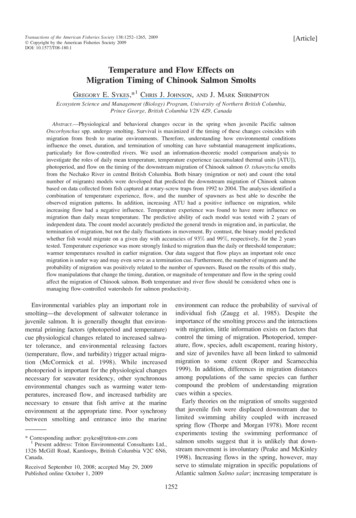
FLOOR PLANS & FEATURESGENERALYour Chinook motorhome is a compact, yet versatile, recreational vehicle loaded withfeatures designed for your comfort and convenience. To help you in locating and identifyingthese features see the drawing on pages 5-8. Note that, while only the dinette option is shown, allother components are identical among the three floor plan options (dinette, club and twin-bed).Also, many of the features shown are options and may or may not be in your motorhome.SYSTEMS MONITOR PANELAt the press of a button you can determine the fluid levels in the fresh water tank, wastewater holding tanks, and LP gas tank from the systems monitor panel located above the closetdoor (refer to the chapter on the waste water system for false tank readings). This panel alsoincludes the monitoring of the charge level of the coach batteries.APPLIANCESYour motorhome is loaded with top-of-the-line, name brand appliances. Operatinginstructions and specifications for these appliances can be found in your owner's packet.Appliance specifications are also listed on a label located on the inside of the closet door.COACH BATTERY SYSTEMAll models of the Chinook motorhome come with a state-of-the-art battery system thatincludes a Low Voltage Disconnect (LVD) and a "Smart" solenoid. With the LVD, accidentaldrainage of your coach batteries will be minimized, if not eliminated entirely. With the "Smart"solenoid, you will be able to charge your coach batteries as well as your vehicle battery, whileeliminating the possibility of accidentally draining your vehicle battery through the coach batteriesor vice-versa. Refer to page 20 on the electrical system for more information.TOWING PACKAGEA towing package is included as a standard feature on the Chinook Motor home (Rated @5000 Ibs. with a 500 Ib. Tongue weight). This includes the trailer hitch as well as tail lightelectrical hook-ups. The tail light electrical hook-ups can be found on the extreme rear of thedriver's side frame rail. Review the section "Loading and Towing" in the next chapter for safetowing procedures.CLOCKThe clock in your motorhome is operated off a battery, which should last approximately oneyear. To reset the clock, first remove the clock from the cabinet by twisting it counter-clock-wise,and then turn adjustment knob on the back.LRev. 1-1I
L.---. .Rev. 1-1- --:-.FLOOR PLANS & FEATURES
Rev. 1-1FLOOR PLANS & FEATURES
Rev. 1-1FLOOR PLANS & FEATURES
Rev. 1-18FLOOR PLANS & FEATURES
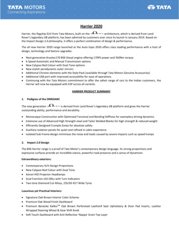
FLOOR PLANS & FEATURESSLEEPING ACCOMMODATIONSSleeping accommodations vary from model type and floor plan and may even be unique to yourmotorhome, if you ordered it with special options. The sofa-bed, offered in the Club and Dinettefloor plans, is folded out to the sleeping position as shown below. On Dinette floor plans, thesofa-bed forms a larger bed with the dinette seats when they are configured with the dinette tablelowered as shown below.SOFA-BEDTO CONVERT SOFA-BED TO SLEEPING POSITION PULL U P AND OUT ON FRONTBOTTOU EDGE OF SOFA AS INDICATED BY ARROWS.DINETTE-BEDSTEP 3.LOWER T A B U TOP TO SUPPORTCLEATS ON SEATS BY ROTATINGBRASS HINGE ASSEMBLY ABOUTLOWER WALL SUPPORT.STEP 2.TILT TABLE TOP DOWNTO DISENGAGE FROMSUPPORT CLEATSTEP 4.PLACE SEAT BACK CUSHIONSFROM BOTH SEATS ONTO THETABLE TOP TO FORM A LEVELSLEEPING SURFACE.
VEHICLE OPERA TlONPLANNING YOUR TRIP, BEING PREPAREDPlanning your trip is an exciting time - and a time when you are likely to forget somethinglast minirt !n ish tn net.imnnrtant. .r - . --. . in. vniir--. .--.a-- reariv'---J.Being properly prepared is the key to getting the most enjoyment from your motorhome,and that's why we are offering the following suggestions as a guide. Review them before startingout, refer to them when you are on the road, and then note the items you have forgotten so yournext trip will be even more fun. Plan your trip carefully. Consult maps and guide books so youwill be familiar with road conditions, roadside parks, rest areas and campsites. Be sure that allyour equipment is serviced and ready for travel. . , a ,Lo w . -. - - 9 .wCheck all of the following:1. All fluids, including motorhome engine crankcase oil, transmission fluid, power steeringfluid, radiator reservoir level, master cylinder brake fluid, electrolyte level of batteries,windshield water reservoir level.2. Inspect wheel lugs for tightness.3. Examine all tires for road damage. Inflate to the pressure recommended by the chassismanufacturer and note that this pressure is for cold tires (see chassis operator's manual).4. Check oil level in the generator power plant (if installed). Refer to the instructions and themaintenance manual provided by the generator manufacturer for pre-use servicerequirements. Make sure extra oil and other supplies are provided if the motorhome is to beused for extended periods.5. Make certain your jack handle and lug wrench are properly stowed and in good workingorder.6. Check to see that your 110-volt power cord is stowed in its compartment.7. Be sure your fire extinguisher is secured and easily accessible.8. Check to see that such accessories as the plastic sewer hose with fittings and a watersupply hose (a garden hose approved for 125 psi service is adequate) are on board.9. Fill water tank, if required (see section on Chinook water system).10. Make sure drain line cap and holding tank knife valves are closed and secured.11. Check all stop lights, running lights and other safety items.12. Put your Chinook motorhome items in "travel" condition. This means following suchcommon-sense procedures as securing any loose items that could shift while you aretraveling. For example, secure refrigerator contents- place lids on containers of liquids - andsecure locking latch on refrigerator door. Be sure cabinet contents are secured and doors aretightly closed. Close and lock all exterior doors and windows.13. Always carry spare fuses of every size used in your vehicle.14. Adjust side view mirrors for maximum visibility.15. Fill the fuel tank, using only the fuel recommended in the chassis operator's manual.16. Fill the LP-gas tank if required.17. Ensure that the antenna and/or satellite dish is retracted to the travel position.WARNING!ALWAYS EXTINGUISH PILOT LIGHTS AND OPEN FLAMES ONAPPLIANCES BEFORE FILLING YOUR GASOLINE OR LPG TANK.WARNING DO NOT ATTEMPT TO MOVE VEHICLE WITHOUT RETRACTING SLIDE (S)AND AUTO LEVELERS
VEHICLE OPERA TlONLOADING AND TOWINGWhen loading up your motorhome it is important to observe its various weightlimitations to ensure that it handles safely on the road. This includes not only thecargo in the motorhome itself but also any vehicle or trailer that is towed. Dealerinstalled equipment and towed vehicle tongue weight will reduce Cargo CarryingCapacity of your Chinook.MOTORHOME \kTlGlll IHFORLIATIOW1I11 MINUS Ff4ESH WATER W f l t l l l OFHltillS LP C I S WEIGHT O!&);US SCWR O FGALLOIlS8 11 3 LBltALF GALLONS @ 4 5 L W L L-PLRSOIIS O 154 L0,PERSOHCCC FOR TIIIS MOTORIIOME'.-I1III II IIWARNING: Exceeding the cargo weight capacities of your motorhome can causeundesirable handling characteristics and may create a safety hazard. If you modifyyour motorhome b y adding racks not supplied by the manufacturer your warranty maybecome invalid.LJust as care should be taken to prevent unsafe loading of the motorhome itself, careshould be taken to prevent unsafe towing of trailers. The vehicle owner's manual provided byFord should be consulted for guidelines on safe towing.WARNING: Exceeding the tongue weight capacity of the trailer hitch can causeundesirable handling characteristics and may create a safety hazard.Rev. 1-1
VEHICLE OPERA TlONSTARTING UP AND READY TO LEAVEWith your preparation and final checkouts completed, you're ready to leave. However,note the following before leaving:MAKE DOUBLE SURE SLlDES ARE RETRACTED AND LEVELING JACKS ARE UP!!1. When starting, warming up and operating your engine, you'll get the best results and theperformance you want by following the instructions in your chassis operator's manual.2. Seat belts are a vital safety feature in your Chinook motorhome. All seat belts should befastened while your motorhome is in motion. Seats not equipped with belts should not beoccupied while the vehicle is in motion.AT LAST, YOU'RE ON THE ROAD!Once you've become accustomed to the feel of the controls and can accurately gaugedistances and the length and width of the vehicle, your Chinook motorhome is like driving yourfamily car. It's easy to handle, maneuver and park. However, be cautious when maneuvering soyou allow for the extra length and width of the motorhome. Check your side view mirrorsfrequently for approaching traffic from the rear.When on the road, remember that higher speeds may result in a sharp increase in fuelconsumption. Always allow for the extra height of your Chinook. It's approximately 10' withoutroof air conditioning and 10%' with it. Avoid low overhead clearance areas such as low roofs atservice stations. This is especially important as you drive with the overhead vent open or if youhave a roof storage pod or air conditioner. When parking, remember that the rear wheels arewider than the motorhome. Also, when parking on an incline, your front wheels should be turnedinto the curb in the direction of the roll as an aid to your parking brake.rnChanqinq a TireSee your chassis operator's manual for tire changing instructions. Your fully loadedmotorhome is very heavy, and the lug nuts usually are set with a power torque wrench whichmakes them extremely difficult to remove. Obtain road service (see Ford's service number below)whenever possible, and only attempt to change tires yourself when it is an emergency situation.FORD MOTOR HOME OWNERS SERVICE LOCATOR HOTLINE NUMBERThis service provides 24-hour, 7-day-a-week assistance in contacting a dealership, arranging aservice appointment and providing a dealership contact person name. This service can alsoassist in locating towing service, if needed.LRev. 1-1
VEHICLE OPERA TlONWARNING: Loosening the rear lug nuts may release both outside and inside wheels.Do not attempt to remove lugs without having your jack i n position to absorb the fullweight of the motorhome.Fire and Life SafetyYour motorhome is equipped with the following pieces of safety equipment that should bechecked prior to your departure:1. A properly rated fire extinguisher located just inside next to the coach door. Check yourextinguisher on a regular basis for proper charge and make sure it is operabie.2. A CO (carbon monoxide) monitor located above the closet door.3. An LP gas detector located at the bottom of the galley cabinet.4. A smoke detector located on the ceiling near the bathltoilet cabinet.Emerqencv ExitsThe main coach entrance door is designated as the main emergency exit. The passenger door isdesignated for use as an alternate emergency exit. These exits should be kept unobstructed andfree to open completely.Emerqency StartIn the event that the vehicle (chassis) battery is drained, you can tap into the coach batteries withthe "Vehicle Boost Start" switch, located above the driver's seat to start the engine. Note that thisswitch needs to be depressed while simultaneously turning the ignition key on.Auxiliaw Liqhts (Optional)Turning on driving lights is accomplished as follows:1. To turn on driving lights, the switch should be in the "Driving Lights" position; this switchoperates independently from the headlamps (Located in the overhead switch cluster).CAUTION: Traffic rules in many states require that fog lights only be used when theheadlamps are set in the low beam position and that driving lights only be used withthe headlamps set in the high-beam position.LRev. 1- 1
CHINOOK CUBETMSLIDEROOMSlide-out OperationSlide Room Extend1. Set Emergency Brake.2. Insert key in slide panel and turn to the on position.3. Wait until the amber light is on constantly (It flashes while the air seal is deflating)rn4. When the amber light is on constantly press and hold the button in the extend position (Thiswill retract the travel locks and extend the room)5. Continue holding the button in the extend position until the room is fully extended (NOTE: DONOT RUN THE ROOM PART OF THE WAY OUT AND ATTEMPT TO RETRACT IT, THIS MAYCAUSE THE SYSTEM TO FAIL)6. Release the button and turn off the key (This will re-inflate the air seal)Slide Room Retract1. Set Emergency Brake.2. Insert key in slide panel and turn to the on position.3. Wait until the amber light is on constantly (It flashes while the air seal is deflating)4. When the amber light is on constantly press and hold the button in the retract position.L5. Continue holding the button in the retract position until the room is fully retracted and the travellocks have fully extended and the red pump indicator light turns off. (NOTE: DO NOT RUN THEROOM PART OF THE WAY IN AND ATTEMPT TO EXTEND IT BACK OUT, THIS MAY CAUSETHE SYSTEM TO FAIL)6. Turn the key to the off position (This will re-inflate the air seal)Slide-out Manual RetractionIf for any reason the slide or auto levelers will not retract, DO NOT ATTEMPT TO FIX THEMYOURSELF. Immediately call the Chinook Service Department at 1-800-552-8886. They willwalk you through the Manual Retraction Procedure.LRev. 1-1
CHINOOK CUBETMSLIDEROOM9Chinook CubeTMComponents/Trou bleshooting-The following is a list of the major components of the hydraulic system in your Chinookmotorhome. This list should give you a better understanding of how your Chinook CubeTMworks.(See page 16) If your motorhome exhibits any malfunction in these components please call theChinook Service Department immediately at 1-800-552-8886, or if it is after business hours callJason Schmidt at 509-949-0173 or Mike Undenvood at 509-930-2072CAN (Controlled Area Network). System of computer operated switches and relays.Connects all components of Auto Leveling Jacks, User Controls, and Slide operatingsystem. Located under the motorhome (in the drivers side front storage bin)Air Seal. Fills area between Chinook CubeTMand the main fiberglass body. lnflates anytime the key to the room slide system is in the off position, sealing out weather or water.Deflates to allow the room to slide in or out.Air Compressor and Tank. lnflates the Air Seal and provides air for the Automatic RideLeveling Airbag System.-U.,rl-r.l:r. D . m m . . r-r\rl D l r r l r - , m : rnyuIauII r u I I I p a l l u ntsatzl VUII.D v n t i A n ethn m n n t t n r / n i l m r n e e a n r n \rIUVIUG LIIG n-nt,npuvvc \ V I I p c a a u i c LVjIIIUVC hn PhinnnbLIICulIIIIuunCubeTMin and out, as well as level the jacks. Located under the motorhome (in the driversside front storage bin)User Interface. Allows the user (you) to operate the Chinook CubeTMsystem, and monitorthe status of the system. Located on the front drivers side overhead panel, (just above thedrivers seat.)Room Locks. Locks the Chinook Cuben Iin the "in" position while not in use, automaticallyretract to allow the slide out procedure. Located on the top side of the room. Mounts to themotorhome.mHall Effect Sensor. Determines the position of the Room Locks to determine whether ornot they are deployed (locked) or retracted (unlocked). Located next to Room Locks on theupper side of the Chinook CubeTMSlide Room.Room In Sensor. Located on the Room Locks, detects the room in the "In" position.Room Out Sensor. Located on the hydraulic ram (under slide room) detects the room inC, ,I1-,,bl u l l UUL pUSILIuI I.LRev. 1-1
mIAUTOMA TIC LEVELING JACKS/AIRBAGSLeveling ComponentsYour Chinook motorhome comes standard with two leveling systems. One works when the vehicleis in motion, one when it is parked.AIRBAGSWhile in motion your Chinook motorhome is kept level and rigid on the road by an AutomaticAirbag System. This system consists of the onboard air compressor, connective tubing, sensors,controls and independent air bladders. These components work together to compensate foruneven loads, heavy towing, and uneven road surfaces. (See page 18)LEVELING JACKSAfter you arrive at your destination there is a second leveling system, the Automatic Leveling JackSystem is comprised of four Hydraulic Self- Deploying Jacks each attached to the underside ofyour Chinook frame. They work with the following components of the Chinook CubeTMslidesystem. (See page 16)CAN (Controlled Area Network). System of computer operated switches and relays.Connects all components of Auto Leveling Jacks, User Controls, and Slide operatingsystem. Located under the motorhome (in the drivers side front storage bin)Hydraulic Pump and Reservoir. Provides the power (oil pressure) to move the ChinookCubeTMin and out, as well as level the jacks. Located under the motorhome (in the driversside front storage bin)User Interface. Allows the user (you) to operate the Chinook CubeTMsystem, and monitorthe status of the system. Located on the front drivers side overhead panel, (just above thedrivers seat.)When used in the proper manner this system will detect the list of the motorhome of as little as118 inch from corner to corner and with a push of a button, brace and level the Chinook.Levelinq Jack Operation1.2.3.4.Turn on ignitionSet emergency brakePress the onlauto button on leveling jack panel (This turns the system on)Press the onlauto button on the leveling jack panel a second time (This kicks the jacks to thedown position)5. Press the onlauto button a third time to auto level the coach or press the upldown, Ieftlrightarrows to manually level the coach.6. To store the jacks press the off button and then press the store button.7. NOTE: BE SURE TO STORE THE JACKS BEFORE ATTEMPTING TO DRIVE THE COACH.I
IAUTOMATIC LEVELING JACKS/AIRBAGSI ILLUSTRATIONRev. 1-11IILLUSTRATION2II
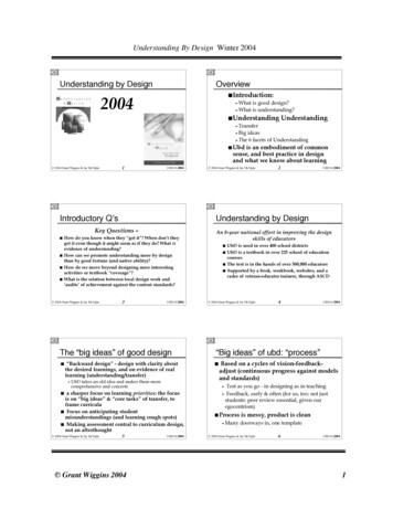
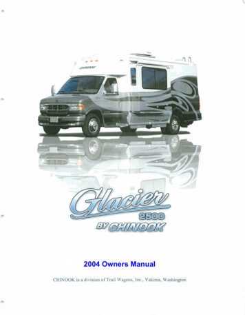
Air Pump – Chinook Glacier (2004)Note blue wires above pump. These terminate in a fuse holder containing a15 amp fuse. This is a power circuit.Note canister to the right of the air/water separator. (This is the item withthe large brass nut on top, with wires coming out the bottom.) This is thepressure switch for the air compressor.Note that the orange wires terminate in another fuse holder. This one is a 5amp fuse that appears to be the control circuit (part of the pressure switchloop).
-ELECTRICAL SYSTEMGENERALThe electrical system consists of IIOV AC and 12V DC appliances supplied by powerthrough a 100 amp converter and distribution panel. i t OV power is available either through a1lOV receptacle provided at an RV park or campsite ("shore power") or through the optionalgenerator set as well as a I000 watt inverter. 12V power is available through the converter whenplugged into shore power or from two coach batteries. A schematic of the coach power system isshown at the end of this chapter.IIOV SYSTEMShore PowerThe connection to IIOV shore power is made through a power cord located in the "servioecenter" on the driver's side towards the rear. To remove the cord, simply open the cover and pullthe cord out to the required length (26' is available). When leaving a campsite, be sure that thecord is removed from the receptacle and stowed in its compartment. Failure to store it properlycould result in extensive damage.Note: Shore power connections are rated for 30 amps Sewice.2CAUTION: Cord cap adapters should not be used, because this could result inconnecting the motorhome to an improperly rated source.Generator SetThe optional generator set is located at the rear passenger side of the motorhome. Themanufacturer of this generator has provided complete operating instructions for the unit installedby Chinook. These instructions, contained in the owner information and warranty package,should be read completely before attempting to operate the generator. In addition to the switchprovided on the front panel of the Genset, all models have a generator start switch above thewardrobe door and some models have a second optional generator start switch above the driver'sseat. The generator provides 4000 watts of power to charge your batteries as well as power yourIIOv and 12v appliances.Breaker PanelThe 1 10V distribution panel is Iocated at the bottom of the wardrobe on Glacier models.Breakers are used to protect the 110V electrical system. These circuit breakers do not resetautomatically and must be turned off, then returned to the *Onwposition. Continued tripping of thebreakers indicates an electrical problem that should be checked by a service technician. Allduplex outlets are GFCI protected by the GFCI outiet located just inside the side entry door.There are dual buss panefs, one for shore power, and the other for the inverter.Automatic Transfer SwitchAn autarnatic transfer switch, located in the wardrube, senses which source of 110V poweris in use (shore power or generator) and will switch to that source. However, if both the generatorand shore power happen to be on at the same time, the generator will take priority- The owner'smanual for the generator should be reviewed for further information.Rev. 1-1
ELECTRICAL SYSTEMAppliances110V power is used to run the following appliances and components (see 110V system atthe end of this section)1. Converter2. Microwave (run with inverter)3. Refrigerator4. Air Conditioner5. GFI protected 110V Receptacles for portable appliances6. Digital Satellite System (DSS) receiver (optional)7. "Nu-Heat" floor heating pad (optional)8. Television (s) (run with inverter)9. Coach stereo system (run with inverter)NOTE: The microwave and air conditioner (and optional DSS) will only operate o nIIOV, while the refrigerator will operate on I I O V , 12V or LPG.12V SYSTEM (COACH)Most of the appliances in the Chinook motorhome run off of 12V power. As noted in theprevious section, the two exceptions are the microwave and air conditioner, which will only run offof I10V power. 12V power is supplied through the 100 amp power converter (running off of 110Vshore power or the generator) or through two coach batteries. Some auxiliary 12V power is alsosupplied from the roof mounted solar panel.2000 Watt Prosine Inverter1ConverterThe inverter allows you to run some 110v AC appliances without being connected to shore power.Inverters work by producing a 60 hertz sine wave able to safely power any 110V appliance.Prosine inverters come with a monitor which will shut down the inverter when battery voltagereaches 12V DC, or when it detects shore power. Using the inverter can be a very power intensiveprocess and should be used with discretion. The built-in power converter is required to convert110V power to 12V power. When shore power is available or the generator is turned on, 12Vpower is supplied through the power converter to all appliances including power to charge thecoach batteries. As noted earlier, the power converter is located in the bottom of the wardrobe.The converter supplies 100 amps to the 12V system. It has 4 stages, and automatically switchesbetween bulk, absorption, float, and quick charging stages, as neededFuse PanelAil 12V circuits are protected with properly rated fuses or automatic reset circuit breakers.There are three exterior circuit breakers. One breaker is a 200 amp panel for the slide pump, one100 amp panel for the generator, and one 100 amp panel for the main power network. If thebreaker continues to trip, however, the system should be checked by a service technician todetermine the cause.The main 12V converter circuits are protected by fuses located inside the converter.LRev. 1-1
ELECTRICAL SYSTEMCoach BatteriesWhen no shore power is available, 12V power is supplied through two 6-volt deep cyclecoach batteries. To activate the system (whether or not the engine is running), the "CoachBatteries" switch must be in the "On" position. This switch is located in the switch cluster abovethe driver's seat.The coach batteries can be charged through shore power, the optional generator, orthrough the vehicle alternator, when the engine is running. In order to run the 12V system off ofthe coach batteries or charge the batteries from 110V power, the "COACH BATTERIES" switchmust be in the "ON" position. The green light labeled "IN USEICHARGING" will be lit when thecoach batteries are in use or being charged.hTo ensure that no battery power is lost over a long storage period the "COACHBATTERIES" switch should be in the "STORE" position.When the vehicle engine is running, the coach batteries will be charged through the alternator,regardless of whether the "COACH BATTERIES" switch is in the "ON" or "STORE" positions.Note, that the "Smart" solenoid (located under the hood) prevents the vehicle battery from beingdrained by the coach 12V DC system. However, should the vehicle battery become drained forsome other reason, the vehicle can be started using power from the coach batteries by activatingthe "VEHICLE BOOST START" switch while simultaneously turning the ignition key on.NOTE: If the "COACH BATTERIES" switch is i n the "STORE" position when shorepower i s plugged in, an alarm will be activated and the red light labeled "SWITCH TOON IF LIT" will be illuminated. In this situation, turn the switch to the "ON" position;the alarm will stop and the red light will turn off. Following this procedure will ensurethat the coach batteries are charged when 110V AC power is available.mLow Voltaqe DisconnectAn important feature of the 12V system is the Low Voltage Disconnect (LVD) module. TheLVD module, which is located inside the coach on the bottom of the wardrobe cabinet, serves thefollowing two functions:1) Warns occupants when the coach batteries are low.2) Prevents the batteries from being completely drained, when they have accidentally beenleft on and no one is in the motorhome.As the coach batteries are being discharged, the LVD module senses the voltage level.When the voltage level reaches a preset value of 11.5 volts, the LVD activates an audible alarm.This alarm is a signal to the occupant that the LVD module will disconnect the coach batteriesfrom the distribution panel within 60 seconds. The occupant has the choice of letting the LVD
the opportunity to work with his service crew in solving it. 2. If the difficulty cannot be resolved to your satisfaction by your local dealer, contact the service manager at the Chinook factory for assistance by calling: 1-800-552-8886 This double service backup is your best assurance that you have made the right decision in choosing a Chinook.