Transcription
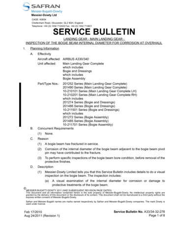
MULTI TANKMONITORINGSYSTEMPNEUMERCATORLiquid Level Control SystemsPeter SinkiwskijDigitally signed by Peter SinkiwskijDN: cn Peter Sinkiwskij, o Pneumercator Co., Inc., ou Headquarters,email peter@pneumercator.com, c USDate: 2019.05.30 19:20:24 -04'00'OPERATION &MAINTENANCE MANUALDRAWING NO. 20001 REV. AMODEL TMS2000 and TMS3000(Covers Firmware versions Vxx.99.xx, Vxx.00.xx, and Vxx.01.xx)(Vxx.00.64 and Vxx.01.21 firmware versions referenced for manual) COPYRIGHT 2019 PNEUMERCATOR CO., INC.1785 EXPRESSWAY DRIVE NORTHHAUPPAUGE, NY 11788TEL: (631) 293-8450FAX: (631) 293-8533http://www.pneumercator.comTMS Operations and Maintenance Manual.docxMay 30, 2019
OPERATION & MAINTENANCE MANUALTMS2000/3000Note: Refer to the model-specific INSTALLATION MANUAL for complete installation details.TABLE OF CONTENTSPageSection11.11.21.3SYSTEM OVERVIEWFront Panel Description . 5Display . 6Audible Annunciator . 6Section2OPERATION2.1 Power-Up Sequence . 72.2 Overview of Operating Modes/System Function Tree . 82.3 View Mode Details . 92.4 Access Mode . 112.4.1 Logs . 162.4.1.1Shift Inventory . 172.4.1.2Delivery . 182.4.1.3Bulk Sales . 192.4.1.4Thefts . 202.4.1.5Product Reordering Report . 212.4.1.6Bottom Water Removal . 222.4.1.7In-Tank Leak Test Results – Detailed . 232.4.1.8In-Tank Leak Test Results – History . 242.4.1.9LS300 Line Leak Test Results . 252.4.1.10 Alarms . 262.4.1.11 Events . 272.4.2 In-Tank Leak Test Scheduling . 292.4.3 Configuration. 332.4.3.1Header . 342.4.3.2Tank . 382.4.3.3Probe. 452.4.3.4Relay Outputs – Tank/Probe Triggers. 482.4.3.5Relay Outputs – Contact Closure Input Triggers . 492.4.3.6Relay Outputs – Leak/Point Level Sensors (ISCC) Triggers . 502.4.3.7Relay Outputs – LS300 Line Leak Test Failure Triggers . 512.4.3.8Relay Outputs – Site-Specific Triggers . 522.4.3.9Relay Mode . 532.4.3.10 Contact Closure Inputs. 552.4.3.11 Leak/Point Level Sensor (ISCC) Inputs . 572.4.3.12 Inventory . 592.4.3.13 Theft . 612.4.3.14 Modem . 622.4.3.15 Dial-Out . 642.4.3.16 In-Tank Leak Test Configuration . 662.4.3.17 Analog Outputs . 692.4.4 Clock (Date/Time) . 702.4.5 Initialize Data . 71Section33.13.23.3PRINTER SERVICINGRibbon Replacement (900438-x, Impact Printer). 72Paper Replacement (900438-1/900438-3/900438-5, Receipt-Style Impact Printer) . 72Paper Replacement (900438-2/900438-4/900438-6, Autowinder Impact Printer) . 73Appendix ADESCRIPTION OF SYSTEM MESSAGES (ALARMS/EVENTS/WARNINGS) . 74Appendix BMAINTENANCE . 80Appendix CDIP SWITCH SETTINGS (900430-1/900461-x) . 82TMS Operations and Maintenance Manual.docxMay 30, 2019
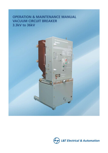
OPERATION & MAINTENANCE MANUALTMS2000/3000SECTION 1 – SYSTEM OVERVIEW1.1 FRONT PANEL DESCRIPTIONThe front panel of the TMS is available in four different configurations as listed below:-1. Console without LED display, without internal printer-2. Console with LED display, without internal printer-3. Console with display and internal impact receipt printer-4. Console with display and internal impact printer w/ autowinderThis manual describes operational procedures pertaining to -2, -3, and -4 consoles. Refer to TMS CommunicatorInstruction Manual for operating the TMS via TMS Communicator software.As illustrated in Figure 1.1 below, the TMS front panel consists of an LED data display presented in either Englishor Metric units, depending on the site’s requirements, with visual alarm and mode annunciators, audible alarmannunciator, user-friendly pushbutton controls, security lock, and optional impact printer with or without autowinder.PNEUMERCATORPNEUMERCATORLiquid Level Control System sLiquid Level Control System sTMS 3000 TMS 3000LEAKSP 1SP 2PAPERFEEDPAPERPRINTFEEDTANK MANAGEMENTTANKSYSTEMMANAGEMENT SYSTEMGALLEAK3.3.8.8.1.0.4.8.5.%GAL%LTRSP 2ULLULLSP 3SP 3TANK IDWATERGROUPIDWATERTANK IDGROUP IDTANKMODESELECTMODEPRINTREVIEWEDITLTRSP 1STEPREVIEWGROUPSTEPSELECTEDITTANKTESTSELECTGROUP EDITSELECTINMM F CTESTEDITFigure 1-1 – Front Panel OverviewTMS Operations and Maintenance Manual.docxMay 30, 2019PAGE 5
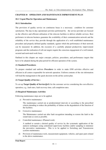
OPERATION & MAINTENANCE MANUALTMS2000/30001.2 DISPLAYThe front panel display consists of a nine-digit, seven-segment, quasi-alphanumeric super bright LEDdisplay, providing on site viewing of current inventory data, alarms, errors, report logs, as well as, setup and configuration data. Five high intensity point LEDs annunciate alarm conditions visible up to75 feet or 25 meters away from console. Five additional LED annunciators provide indication of unitsof measure of the currently selected display data. See Figure 1.2 below.TMS 3000 TMS 3000LEAKSP 1SP 2SP 3WATERTANK MANAGEMENTTANKSYSTEMMANAGEMENT SYSTEMGALLEAK3.3.88.83.1.8.0.8.4.1.8.0.5.4. .8.5.LTRSP 1%GAL%LTRSP 2ULLULLINMM F CSP 3TANK IDGROUPIDWATERTANK IDGROUP IDFigure 1.2: TMS Display Layout1.3 AUDIBLE ANNUNCIATORA front panel horn is provided to annunciate both user-selectable alarms as well ascommunications failures. The horn can be silenced manually by pressing ANY pushbutton,automatically by eliminating the alarm condition, or by programming an audible alarm shutoff.Under alarm conditions, the beep rate of the annunciator varies with the alarm type asfollows:Alarm GroupTankSensorContact ClosureSystemAlarm TypeFailed In-Tank LeakTest3SP Firmware: SP16SP Firmware: Critical High, Critical Low3SP Firmware: SP26SP Firmware: High High, Low Low3SP Firmware: SP36SP Firmware: High, LowBottom WaterLeakPoint Level (High, Low, etc)FaultAllAllTMS Operations and Maintenance Manual.docxBeep RateFast (50ms)Medium Fast (100ms)Medium Slow (200ms)Slow (400ms)Slow (400ms)Fast (50ms)Slow (400ms)Slow (400ms)Slow (400ms)Slow (400ms)ms millisecondsMay 30, 2019PAGE 6
OPERATION & MAINTENANCE MANUALTMS2000/3000SECTION 2 – OPERATION2.1 POWER-UP SEQUENCEUpon application of AC power, the TMS performs a series of tasks prior to normal operation. These include thefollowing:1. A self-test to verify integrity of both system program and data memories, system I/O, and data acquisition interfaceelectronics. Display is blank during this process.2. Retrieval and verification of configuration and set-up data.Display shows “rEAding / Config“ (Reading / Configuration).3. System initialization, including pre-start-up calculations.Display shows "system / Init" (System / Initialization).4. Visual display and audible alarm check.Display activates all LEDs including numeric display, Alarm and Units LEDs, and audible alarm beeps twice.5. Begin normal operation, display any error messages. For a description of system error, warning and info messages,refer to Appendix A.Note: In cases where the TMS power has been turned off for more than one to two minutes, a power-up sequencewill generate the following warning message on the display and a similar message on the optional front panel impactprinter, "Warn21 / Pwr faiL" Warning 21, Power Failure.This message is normal, and is just informing the user that the TMS has detected a power failure. This condition canbe acknowledged by the user by holding the MODE button until the TMS beeps once while the message is displayed.TMS Operations and Maintenance Manual.docxMay 30, 2019PAGE 7
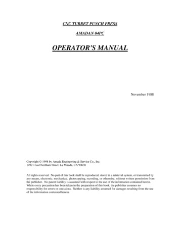
OPERATION & MAINTENANCE MANUALTMS2000/30002.2 OVERVIEW OF OPERATING MODES/SYSTEM FUNCTION TREETMS front panel operation is defined by three user-selectable modes, View, Test, and Access, all selected using theMODE and TEST pushbuttons. See Figure 2.2, System Function Tree below.ANALOG OUTputsin- TANK LEAK tes tDIAL OUTMODEMTHEFTINVENTORYSENSoR INPu tCC INPUTRELaY MODERELaY SITEINITialize D ATACLOCKCONFIGur ationRELaY Line Leak Pane lEVENTSRELaY SENSorALARMSRELaY CCLINE LEAK tes t resu l tsRELaY TANKin- t ank LEAK tes t HISTo ryPROBEin- TANK LEAK tes t resu l tsTANKWATER remo v a lHEADERproduct ORDERSTHEFTSin- t ank LEAKTEST schedulingbulk SALESDELIVERYLOGINVENTORYACCESSVIEWSYSTEM TESTFigure 2.2: System Function TreeVIEW: View mode is the most frequently used and the default mode of operation for the console. The View modedisplays current tank data, which includes product gross and net (temperature compensated) volumes, percent ofcapacity, ullage, product and bottom water levels, product temperature, and product name. In addition, alarm anderror conditions are annunciated in the View mode. If the system includes the optional impact printer, on demandprinted inventory reports including complete tank/sensor alarm statuses can be generated. See Section 2.3 forcomplete details.ACCESS: Access mode provides access to all of the menus shown in Figure 2.2. In this mode the user can reviewand print report logs; review, edit and print system configuration data; enable or schedule in-tank leak tests; performinitialization functions; read or set the system clock. See Section 2.4 for complete details.TEST: Test mode allows visual verification of display operation, audible verification of the audible annunciator, andself-verification of critical system hardware.TMS Operations and Maintenance Manual.docxMay 30, 2019PAGE 8
OPERATION & MAINTENANCE MANUALTMS2000/30002.3 VIEW MODE DETAILSLooking at the names assigned to the console front panel pushbuttons and display field, note that some appear inwhite lettering, others in orange. Only the black or white-lettered name assignments apply to the VIEW mode.The seven-segment data display is formatted so that the currently selected data item appears on the right-hand side,with the corresponding tank ID to the left, as indicated on the front panel. The LED annunciators on the left-hand sideindicate alarm conditions. An alarm indicator corresponds to the displayed tank when the particular LED is on steady.If the LED is blinking, this indicates that an alarm has occurred on a tank other than the one being displayed.Pushbutton Operation:MODE: The MODE pushbutton functions both as a Display Mode Select (i.e. STEP) and a Product Name Recall. Ifthe user depresses and holds MODE until an Audible beep is heard, the display will STEP to the next display item.See following page for examples of the TMS Display showing varied information. Display items include, in order ofappearance:Display ItemGross Volume (uncompensated)Net Volume (temperature compensated)Percent Volume90% UllageProduct LevelWater LevelProduct TemperatureUnitsGallonsGallons% GallonsGallonsInchesInches FEnglishResolutionx1x1x0.1x1x0.1x0.1x /-0.1UnitsLitersLiters% LitersLitersMillimetersMillimeters CMetricResolutionx1x1x0.1x1x1x1x /-0.1To recall the name of the product stored in the selected tank, depress and immediately release MODE. The productname will appear for two seconds, then the display will revert back to displaying the currently selected data item.TANK SELECT: The TANK SELECT pushbutton is used to select a desired tank for display. Each time TANKSELECT is depressed, the console advances to the next enabled tank and its corresponding tank ID appears on thedata display. This is called MANUAL tank selecting. An automatic tank select or AUTO SCAN mode is also available.In the AUTO SCAN mode, the display automatically and continuously scans through each enabled tank, holding thedisplay for five seconds before advancing to the next tank. This mode is useful for hands-free operation. AUTO SCANis enabled by depressing and holding TANK SELECT until an audible beep is heard. To turn off the AUTO SCANfeature, again depress and hold TANK SELECT until an audible beep is heard. The system is now in the manualmode.TEST: Test mode allows visual verification of display operation, audible verification of the audible annunciator, andself-verification of critical system hardware.PRINT: Depressing the PRINT pushbutton while in the VIEW mode generates an on-demand inventory reportfollowed by an alarm status report for Tanks and Sensors.PAPER FEED: The PAPER FEED pushbutton is used to advance paper through the printer mechanism.NOTE: Alarms, errors or warning conditions, which occur during VIEW mode, will activate the front panel visual andaudible annunciators. The user can silence the audible annunciator by momentarily pressing any front panelpushbutton. The visual annunciator will remain active until the alarm or error condition is eliminated. If subsequentalarms, errors, or warnings occur, the audible annunciator will again be activated.TMS Operations and Maintenance Manual.docxMay 30, 2019PAGE 9
OPERATION & MAINTENANCE MANUALTMS2000/3000See below: Actual TMS Visual representation of Front Panel displayed items, in order of appearance:GAL2.2.8.8.1.0.6.7.9.%GALULLGross Volume 10679 Gallons, Tank 2INTANK IDGROUP ID FLTR2.2.8.8.1.0.5.9.6.%LTRULLNet Volume 10596 Liters, Tank 2MMTANK IDGROUP ID CGAL2.2.8.8.1.0.7.9.7.%GALULLPercent Volume 79.7% of Capacity, Tank 2INTANK IDGROUP ID FLTR8.8.8.8.1.1.3.8.0.%LTRULLMMTANK IDGROUP ID90% Ullage 1380 Liters, Tank 8(90% is default) CGAL2.2.8.8.1.1.0.6.8.%GALULLProduct Level 106.8 Inches, Tank 2INTANK IDGROUP ID FLTR1.2.8.8.1.1.w.2.4.%LTRULLBottom Water Level 24 Millimeters, Tank 12MMTANK IDGROUP ID CGAL9.9.8.8.1.1.7.2.1.%GALULLProduct Temperature 72.1 F, Tank 9INTANK IDGROUP ID FPressing the MODE button until the TMS BEEPS, will advance through the above listGAL1.9.8.d.I.e.s.e.L.%GALULLProduct Type DieselINTANK IDGROUP ID FPress and release MODE to reveal Tank NameTMS Operations and Maintenance Manual.docxMay 30, 2019PAGE 10
OPERATION & MAINTENANCE MANUALTMS2000/30002.4 ACCESS MODE DETAILSANALOG OUTputsin- TANK LEAK tes tDIAL OUTMODEMTHEFTINVENTORYSENSoR INPu tCC INPUTRELaY MODERELaY SITEINITialize D ATACLOCKCONFIGur ationRELaY Line Leak Pane lEVENTSRELaY SENSorALARMSRELaY CCLINE LEAK tes t resu l tsRELaY TANKin- t ank LEAK tes t HISTo ryPROBEin- TANK LEAK tes t resu l tsTANKWATER remo v a lHEADERproduct ORDERSTHEFTSin- t ank LEAKTEST schedulingbulk SALESDELIVERYLOGACCESSINVENTORYVIEWSYSTEM TESTWithin the ACCESS mode there are several levels of menus, as illustrated in the above figure. The main menusinclude LOG reports, LEAK TEST, CONFIGuration, CLOCK read/set, and INITialization of DATA including logs andConfiguration memory. Note: that the LOG and CONFIG main menus contain numerous submenus. These submenuswill be described in detail later in this section. The main menus are as follows:LogThe LOG menu is used to review and print any of the various log reports generated by the TMS. Thesystem does not allow the user to edit any of these reports.Leak testThe LEAK Test menu is used to select, schedule, and enable in-tank leak tests.ConfigThe CONFIGuration menu is used to review, edit, or print system configuration data.ClockThe CLOCK menu is used to edit system date, time, and day.Init dataThe INITialize DATA menu is used to initialize all or selected log report groups, or configurationmemory.TMS Operations and Maintenance Manual.docxMay 30, 2019PAGE 11
OPERATION & MAINTENANCE MANUALTMS2000/3000ENTERING ACCESS MODEThe ACCESS mode is entered by first pressing and holding TEST, and then, while still holding TEST, simultaneouslypressing and holding MODE. After approximately two seconds, the TMS will enter ACCESS mode. The display willappear as follows:ACCESSLogwhere LOG is the first main menuPUSHBUTTON OPERATION:The TMS front panel contains both black or white text, and orange text. Where present, the orange nameassignments apply while in the ACCESS mode.Within the ACCESS mode there are three basic types of operations that the user can perform, REVIEW, EDIT andPRINT, and as seen on the TMS front panel, the three right-hand pushbuttons have different functions assigned tothem for REVIEW and EDIT operations.REVIEW: REVIEW is the normal mode of operation within the ACCESS mode, and is used to examine or review log,configuration, or clock data within the system. REVIEW is available in all menus and sub-menus.REVIEWEDITMODETANKSELECTTESTSTEPGROUP SELECTEDITDWG NO. 20043 REV. N/CFigure 2.4.1: TMS3000 Pushbutton LayoutSTEP: The STEP pushbutton functions both as a STEP-to-the-next-item and a Data Name Recall. If the userdepresses and holds STEP until an audible beep is heard, the display will step to the next menu data item. To recallthe name of the menu data item the user momentarily depresses STEP. The menu data item name will appear fortwo seconds, and then the display will revert back to displaying the currently selected data item.GROUP SELECT: The GROUP SELECT pushbutton functions in the same manner as manual tank selecting in theVIEW mode, except that GROUP is more generic, and refers to the fact that, depending upon which menu the userhas entered, GROUP SELECT will select the next tank, probe, relay, leak sensor, log record, etc.EXAMPLE: If the user enters a relay setup menu, GROUP SELECT will select the next relay, and the GROUP IDdisplay field will indicate the relay number rather than a tank ID. If the user enters the INVENTORY LOG menu, whichstores up to 36 records, depressing GROUP SELECT will step to the next inventory record and the GROUP ID displayfield will represent the inventory record number 1 through 36.TMS Operations and Maintenance Manual.docxMay 30, 2019PAGE 12
OPERATION & MAINTENANCE MANUALTMS2000/3000EDIT: The EDIT pushbutton is used to edit or change the value of the currently displayed data item. If the displayeditem is a menu or sub-menu name, EDIT allows the user to change the menu. If the displayed item is system data,for example, configuration or clock data, the EDIT function is inhibited unless enabled by the EDIT ENABLEpushbutton located on the inside of the front panel. See Figure 2.4.2 for button location. To enable editing, anauthorized user would first unlock and open the front panel, press EDIT ENABLE, and then re-lock the enclosure.This prevents unauthorized persons from modifying stored data since the front panel would normally be locked. Anaudible beep informs the user when editing in inhibited. Once EDIT ENABLE has been pressed, editing is enabledfor as long as the user remains in the ACCESS mode. For additional security, if the TMS is in the ACCESS mode formore than four minutes and detects no user activity on the front panel pushbuttons, the system will time out andrevert back to VIEW mode. Entry back into the ACCESS mode will again require pressing EDIT ENABLE to re-enableediting.PUSH UP ANDRELEASEEDIT ENABLE/THEFT ALARMACKNOWLEDGEEDIT ENABLE/THEFT ALARMACKNOWLEDGEDWG NO. 20045 REV. N/CFigure 2.4.2: Edit Enable/Theft Alarm Acknowledge button locationThe names associated with pushbutton functions during edit operations are labeled in orange on the front panel as (right arrow), (down arrow), and (up arrow), as shown in Figure 2.4.1. : Functions as an ENTER key for blinking data. For numeric data, advances the blinking cursor to the right to thenext digit to be changed. Pressing right arrow while at the right-most digit performs the function of ENTER, andcauses the new or changed entry to be stored. : Decrements the content of the blinking portion of the display. For numeric data this button is used to decrementthe value of the selected digit. For alphanumeric names, decrements through a list of name selections. : Increments the content of the blinking portion of the display. For numeric data this button is used to incrementthe value of the selected digit. For alphanumeric names, increments through a list of name selections.TMS Operations and Maintenance Manual.docxMay 30, 2019PAGE 13
OPERATION & MAINTENANCE MANUALTMS2000/3000WARNINGThis product installed in hazardous, explosiveenvironments. Initial application of AC power to thissystem should occur only after complete verification ofsafe, proper installation by authorized Pneumercatorcertified service personnel. Failure to do so may resultserious injury and/or property damage.TMS Operations and Maintenance Manual.docxMay 30, 2019PAGE 14
OPERATION & MAINTENANCE MANUALTMS2000/3000POWER-UP SEQUENCE: Upon application of AC power, the TMS performs a series of tasks prior to normaloperation. These include in the following sequence:1)A self-test to verify integrity of both system program and data memories, system I/O, and data acquisitioninterface electronics. Display is blank during this process.2)Retrieval and verification of configuration and set-up data.Display shows3)READingSystem initialization, including reasonableness checking of user-entered configuration data, and pre-startupcalculations.Display shows4)ConfigInitsystemVisual display and audible alarm check.Display showsGALLEAK8.8.8.8.8.8.8.8.8.SP 1SP 2SP 3TANK IDGROUP IDWATERLTRLEAK%GALSP 1ULLSP 2INSP 3 FWATER8.8.8.8.8.8.8.8.8.TANK IDGROUP ID%LTRULLMM Cwith all LEDs on, audible alarm beeps twice.5)Begin normal operation, display any error messages. For a description of system error, warning, and infomessages, refer to Appendix A.NOTE: In cases where TMS power has been turned off for more than one to two minutes, a power-up sequence willgenerate the following warning message on the display and a similar message on the optional front panel printer:Warn21Pur faiLWarning 21, Power FailureThis message is normal, and is just informing the user that the TMS has recovered from a power failure of at least1-2 minutes in duration. This may be acknowledged by holding MODE until the TMS beeps once WHILE the messageis displayed.TMS Operations and Maintenance Manual.docxMay 30, 2019PAGE 15
OPERATION & MAINTENANCE MANUALTMS2000/30002.4.1 LOG MENUACCESSLogLogSystem reportsLEAK testLeak test setupConfigSystem configurationClockSet system clockInit dataResets data to initialized valuesReturnExits access menuSystem Logs/Reports: The LOG menu contains various Logs/Reports that are primarily a groupingof historical recorded events that have been captured and stored in the TMS memory. Once the Logcapacity has been reached, the oldest record will be discarded to allow the new entry to be stored.Each Log may be viewed or printed from within each respective submenu. The records may also beretrieved with a Windows-based computer equipped with TMS Communicator software. Logs mayNOT be altered by any user or supervisor to maintain the integrity and accuracy of the system Logs.A brief description of each submenu is provided below. The pages that follow contain completedetails for each Log submenu.Inventory (Inventory. Max records :36): A scheduled Shift Inventory report as configured in the Inventory submenuof the Configuration menu.deLivery (Delivery. Max records: 12): Addition of Product to the storage tank.SALES (Bulk Sales. Max records: 24): Withdrawal of Product from the storage tank recorded only if the Bulk Salesfeature is enabled in the Configuration menu, Header submenu. If Theft is enabled for the specified Tank Channel,the transaction would only be considered a Bulk Sale if the withdrawal occurs during normal business hours asdefined in the Configuration menu, Thefts submenu.tHEFtS (Thefts. Max records: 6): Withdrawal of Product from the tank outside of normal business hours. Thefts areonly recorded if Theft monitoring is enabled for the specified Tank Channel (Tanks submenu/Configuration menu).Orders (Product Order. Max records: 12): The Product Reorder Log is the only Log that is NOT historical but is anon-demand report that provides an estimate of usable Product remaining based on the amount of Product used sincethe time of the last Delivery.Water (Water Removal. Max records: 12): The removal of bottom water, typically from a petroleum storage tank.tank Leak (Tank Leak. Max records: 12): Detailed In-Tank Leak Test results for qualifying petroleum undergroundstorage tanks (USTs).Leak Hist (Leak History. Max records: 14 per Tank): Summary In-Tank Leak Test results for each qualifying TankChannel providing up to 14 months of history by storing the latest passing test per month per tank channel.LIne Leak (Line Leak. Max records: 8): Report is based on the results communicated to the TMS via RS-232 by anexternal LS300 Line Leak console.ALArMS (Alarms. Max records: 24): System Alarms including High, Low and Leak conditions.Events (Errors. Max records: 8): System Errors and Warnings that may represent a critical problem with the TMS.Terms used throughout the LOG submenus are as follows:Gross Volume: The volume of liquid within the storage tank measured in Gallons [Liters].Net Volume: Temperature-Compensated Volume. The Gross Volume is adjusted to the Volume that would beoccupied at 60 F [15.6 C]. This is used for Inventory reconciliation due to the fact that liquids expand andcontract with temperature. The Product Type defined in the Tank submenu of the Configuration menu is used todetermine the rate of expansion for a given liquid.Height: Liquid level measured in Inches [Millimeters].Note: The Volumes and Levels reported will be the TOTAL liquid level unless otherwise indicated. If the TankChannel is equipped and configured with a MP452 probe, the Volumes and Levels reported will includePRODUCT ONLY.TMS Operations and Maintenance Manual.docxMay 30, 2019PAGE 16
OPERATION & MAINTENANCE MANUALTMS2000/30002.4.1.1 SHIFT INVENTORY LOGLogInventorydeLiverySALEStHEFtSOrdersWatertank LeakLeak HistLIne LeakALArMSEventsreturnInventoryDeliveriesBulk SalesTheftsProduct Reordering ReportBottom Water RemovalIn-Tank Leak Test –
OPERATION & MAINTENANCE MANUAL TMS2000/3000 TMS Operations and Maintenance Manual.docx May 30, 2019 PAGE 6 1.2 DISPLAY The front panel display consists of a nine-digit, seven-segment, quasi-alphanumeric super bright LED display, providing on site viewing of current inventory data, alarms, errors, report logs, as well as, set-