Transcription
MODULAR CONNECTION TECHNOLOGIESFOR COMPOSITE W ALLS IN SMRS:DEVELOPMENT AND EXPERIMENTALVERIFICATIONAmit H. Varma, Efe G. Kurt, Jungil SeoOctober 18, 2016DOE NEUP – AMM Presentation
PROJECT GOAL Goal:The goal of the project was to develop andverify connection technologies for steel-platecomposite (SC) walls. Specifics:1.2.3.The verified connection technologies and data etc.should be available in the public domain for easyaccess by industry, regulators, DOEInclude SC wall-to-basemat anchorage, SC wall-towall joints, and SC wall-to-slab connectionsConsider different connection design andperformance philosophies
PROJECT OBJECTIVES1.2.3.4.Develop modular SC wall connection strategies, andevaluate their structural behavior, fabricationefficiency, and construction economy.Develop and benchmark numerical modeling andanalysis techniques that can be used to investigatethe structural behavior, performance and failure of SCwall connections.Conduct experimental investigations to verify SC wallconnection performance.Develop standardized connection details and designguidelines that can be used to expedite the design,review, licensing, and construction processes forSMRs.
PROJECT TASKS Task1 - Selection of connection configurations for theproject is complete. Task 2 –Computational simulation and benchmarkinganalysis work is complete. Expanded state-of-the-artnumerical techniques, concrete material models etc. Task 3 – Design and experimental evaluation of:1.2.3.4.5.SC wall-to-basemat anchorageSC wall-to-wall T-connectionsSC wall-to-wall L-connectionsSC wall-to-slab connectionsSC wall-to-basemat anchorage Task4 - Design guidelines for SC wall-to-wallconnections, and full strength SC wall-to-basematanchorage
MAJOR ACCOMPLISHMENT - 1 Development,N9 - Specification for steel-plate composite SCwalls in safety-related nuclear facilities Instead of ACI 349 code for concrete structures fornuclear facilities but all topics covered Specificationfor SC walls and associated connectionsCopyright Amit H. Varma, Purdue University, USA Appendix9/30/16review, balloting, and publication of aconsensus standard for steel-plate composite (SC) walls AISC N690-12s1 (2015 ) - Specification for SafetyRelated Steel Structures for Nuclear Facilities IncludingSupplement No. 1 - Published in August 2015
CONSENSUS STANDARD9/30/16Copyright Amit H. Varma, PurdueUniversity, USA
CONSENSUS STANDARD9/30/16Copyright Amit H. Varma, PurdueUniversity, USA
ORGANIZATION OF APPENDIX N9–N9.3.6 Strength Under Combined Forces N9.2DesignAnalysisRequirementsN9.4of SCWall Connections–––––N9.2.1 General Provisions–N9.4.1 General ProvisionsN9.2.2Effective onsStrengthN9.2.5 Required StrengthsCopyright Amit H. Varma, PurdueUniversity, USAN9.1DesignN9.3 Designof RequirementsSC Walls– N9.1.1 General Provisions– N9.3.1 Tensile Strength– N9.1.2 Design Basis–Compressive Strength– N9.3.2N9.1.3.SlendernessRequirement– rength–– N9.1.5 Tie Requirements– N9.3.4 In-Plane Shear Strength– N9.1.6 Impactive and Impulsive– N9.3.5 Out-of-Plane Shear StrengthN9.1.7 Around Openings9/30/16
AISC N690S1: APPENDIX N9.4.2CONNECTION DESIGN PHILOSOPHY
AISC N690S1: APPENDIX N9.4CONNECTION DESIGN PHILOSOPHY
AISC N690S1: APPENDIX N9.4.3CONNECTION DESIGN
AISC N690S1: APPENDIX N9.4.3CONNECTION DESIGN
AISC N690S1: APPENDIX N9.4.3CONNECTION DESIGN
MAJOR ACCOMPLISHMENT - 2 Development,review, balloting, and publication ofan AISC Design Guide for steel-plate compositewalls and connections. AISCDesign Guide No. XX (2016). This designguide has completed two review cycles, and hasbeen accepted by AISC for publication. Typesettingis ongoing right now. Itincludes design examples for both SC walls andconnections based on the findings of this DOEproject.
AISC DESIGN GUIDE: SC W ALLS / CONNECTIONS
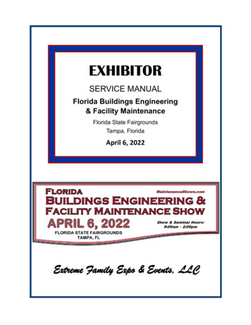
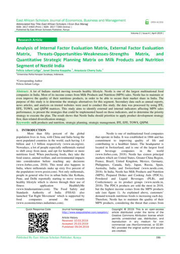
SC WALL-TO-BASEMAT ANCHORAGE CONNECTIONCan be designed either as full-strength or over-strengthanchorage. Full-strength design is preferred and convenientSingle baseplate SC Wall-to-BasematConnectionSplit-baseplate SC Wall-to-BasematConnection
FORCE TRANSFER MECHANISMSMopCTMopCMopCantileverBendingdue touniformreactionTMopCMopTMopCMopTanc TVoutVoutVfrVancVanc
RESEARCH NEEDED TO COMPLETE DESIGN1.Direct shear strength of rebar-coupler anchorsystems. This information is not available in anyexisting design codes / standards, and must beverified through large-scale tests before adoption2.Cyclic performance of SC walls designed with fullstrength connections. Focus on in-plane shearbehavior of SC wall piers and flanged walls.
MAJOR RESEARCH PRODUCTS - 1Kurt, E., Varma, A.H., and Sohn, Y. (2016). “Direct ShearStrength of Rebar-Coupler Anchor Systems for Steel-PlateComposite (SC) Walls.” International Journal of SteelStructures, Springer Press. This paper included results from large-scale tests of #18 and#11 rebar-coupler anchor systems, which were embedded inconcrete with appropriate development length and subjectedto direct shear loading up to failure Key Finding: The direct shear strength of the rebar-coupleranchor systems was governed by the shear fracture failureof the net section area of the coupler, not the shear fractureof the rebar anchor. This net section area was located justafter the end of the rebar anchor threaded into the coupler.
MAJOR RESEARCH PRODUCTS - 1 Thedirect shear strengths calculated using theupdated design equation were within 1% of thecorresponding failure loads from the tests. The load-slip relationships measured from the testedspecimens could be modeled empirically using amodified version of the empirical model proposed forthe behavior of shear studs embedded in concrete.
MAJOR RESEARCH PRODUCTS - 2 KurtEG., Varma AH., Booth P, and Whittaker AS. (2015)“In-plane Behavior and Design of Rectangular SC WallPiers without Boundary Elements”. Journal of StructuralEngineering, ASCE Thispaper presents the cyclic in-plane shear behavior ofSC wall piers with full-strength basemat anchorage. Theanchorage is achieved using rebar-coupler anchorsystems designed as mentioned before Thecyclic in-plane shear behavior was evaluated for SCwall piers with different reinforcement ratio, stud and tiespacing, and wall aspect ratios ranging from 0.60 – 1.0
MAJOR RESEARCH PRODUCTS - 393
MAJOR RESEARCH PRODUCTS - 2
MAJOR RESEARCH PRODUCTS - 2 Epackachi,S., Whittaker, AS., Varma, A.H., and Kurt,EG. (2015). “Finite Element Modeling of Steel-Plateconcrete composite wall piers.” Engineering Structures,Elsevier Science Epackachi,S., Nguyen, N., Kurt, E., Whittaker, A. andVarma, A.H. (2014). “In-Plane Behavior of RectangularSteel-Plate Composite Shear Walls.” Journal ofStructural Engineering, ASCE
MAJOR RESEARCH PRODUCTS - 3 Kurtet al. (2016) includes design equations forcalculating the lateral load capacity of SC wall pierswith full-strength anchorage connections Seo,J., Varma, A.H., Sener, K., and Ayhan, D.(2016). “Steel-Plate Composite SC Walls: In-PlaneShear Behavior, Database, and Design.” Journal ofConstructional Steel Research, Elsevier Science. Seoet al. (2016) develop design equations forcalculating the in-plane shear strength of SC wallswith boundary elements and full-strengthanchorage connections
SC WALL-TO-BASEMAT ANCHORAGECONNECTIONCan only be designed as over-strength anchorage.Preferred due to ease and pace of constructionSC Wall-to-Basemat Anchorage usingnon-contact spliced rebars
FORCE TRANSFER MECHANISMSMopVinpTMopOut-of-Plane MomentVinpAxial TensionVancVancVancVancIn-Plane Shear
RESEARCH NEEDED TO COMPLETE DESIGN1.Design and detailing of non-contact lap splicebetween steel faceplates of SC walls and rebar fromconcrete foundation. This information is not availablein any codes / standards, and must be verified usinglarge-scale tests before adoption2.Cyclic performance of SC walls designed with overstrength connection. Focus on in-plane shearbehavior of SC wall piers.
MAJOR RESEARCH PRODUCTS - 4 Seo, J., and Varma, A.H. (2016). “Experimental Behavior andDesign of Steel-Plate Composite-to-Reinforced Concrete (SC-toRC) Lap Splice Connections.” Journal of Structural Engineering,ASCE, Accepted, In Press This paper presented the results from experimental andnumerical investigations of the axial (tension) behavior of SC-toRC lap-splice connections. The experimental investigationsincluded the parameters: shear reinforcement ratio (ρw), distancebetween SC wall and dowel bar (α), dowel embedment length,and tie bar configuration.
MAJOR RESEARCH PRODUCTS - 4 PRIMARY FINDINGS Force transfer from the steel faceplates (of the SC portion) tothe steel dowels (of the RC portion) can be accomplishedusing stud anchors.The number (n) and strength (Qn) of these stud anchors andties should be designed and detailed to develop the expectedstrength (Nr) of the weaker of the connected parts. The embedment length (Lemb) of the steel dowels within theSC portion will depend directly on the number (n) and spacing(s) of stud anchors and ties, but it is not recommended to beless than the corresponding development length (Ld) of thedowel bars in the RC portion.Shear reinforcement (ρw) ratio greater than 0.5% can provideductility. The steel dowel bars have to be placed at least 1.0xdb,dowel so that concrete struts can be anchored adequately.
MAJOR RESEARCH PRODUCTS - 5 Cyclicin-plane shear behavior of SC wallsdesigned with overstrength connection achievedusing non-contact spliced rebars Tested two specimens SCRC1 and SCRC2 withaspect ratio of 0.6. The non-contact lap splicesbetween the steel plates and rebars were designedusing Seo et al. (2016).
MAJOR RESEARCH PRODUCTS – 5SCRC1 designed to be governed byflexural capacity of RC portion at baseSCRC2 designed to be governed byshear strength of RC portion at base
MAJOR RESEARCH PRODUCTS - 5M nRC/ lw 495 kipM nRC/ lw 495 kipCyclic behavior of SCRC1 governed byflexural yielding of the RC portion at thebase. Does not develop SC wall strengthOverstrength connection demonstratedM nRC/ lw 665 kipM nRC/ lw 665 kipCyclic behavior of SCRC2 also governed bflexural yielding of the RC portion at thebase. Does not develop SC wall strengthOverstrength connection demonstrated
MAJOR RESEARCH PRODUCTS - 5Published in Ph.D. Dissertation of Efe Kurt. The correspondingjournal article is still being prepared
SC W ALL-TO-WALL CONNECTIONS Wall-to-wallT-joints and L-joints are common in plantlayout configurations. See plan view belowL Joint
SC W ALL-TO-WALL JOINTS Full-strengthconnection design philosophy Developsthe expected strength of the weaker of the twoconnected walls Failure mode: flexural yielding (ductile) with formation ofplastic hinges in SC walls Over-strengthconnection design philosophy Developsfailure in the joint, but the strength is greater thanthe calculated required strengths (twice the seismic load) Inorder to implement either philosophy, need to calculateJOINT SHEAR STRENGTH to either prevent it (for fullstrength) or have over strength with respect to it.
FORCE TRANSFER MECHANISMSAxial Tension in Discontinuous WallResulting Joint Shear Force to AchieveFlexural Yielding in Cont. WallsNr /2Nr /2MrNr /2MrNr /2Nr /2Nr /2Nr /2Nr /2Mr /jTNr /2Nr /2NrMr /jTV jsNr /2Nr /2Mr /jTMr /jTNr /2Nr /2V js max(Nr /2,Mr /jT)
FORCE TRANSFER MECHANISMSFor In-Plane Shear DemandFor Out-of-Plane Shear DemandResulting Joint Shear Force
RESEARCH NEEDED TO COMPLETE DESIGN1.Joint shear strength for SC walls with T-joints, Ljoints, etc. There are no codes / standards thatprovide this information. ACI 349 includes joint shearstrength for RC joints, but large-scale experimentalverification is needed to extend to SC joints2.Joint shear strength for T-joints and L-joints can bedifferent, and need further evaluation
Seo, J., and Varma, A.H. (2016). “Behavior and Design of Corner or L-Joints in SC Walls.”Structures, Elsevier Science, Submitted May 2016.MAJOR RESEARCH PRODUCTS - 6 Seo,J. and Varma, AH (2016). “Joint ShearStrength of SC Wall-to-Wall T-Joints.” Journal ofStructural Engineering, ASCE, Submitted for reviewand publication. Seo,J. and Varma, AH. (2016). “Behavior andDesign or Corner or L-Joints in SC Walls.”Structures, Elsevier Science, Submitted for reviewand publication Ph.D.Dissertation of Jungil Seo, Purdue Univ.
MAJOR RESEARCH PRODUCTS - 6 Themajor research finding is that the joint shearstrength can be calculated conservatively, and withreasonable accuracy using ACI 349 joint shear strengthequation for RC joints γ 12 for SC wall T-joints γ 8 for SC wall L-joints Anothermajor finding is that the presence of tie bars,or additional shear studs does not have a significantinfluence on joint shear behavior or strength.
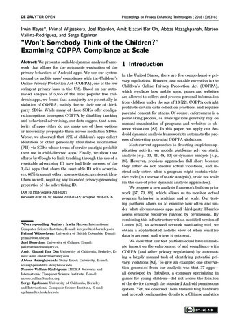
MAJOR RESEARCH PRODUCTS - 6Details of T-Joint SpecimensDetails of L-Joint Specimen
MAJOR RESEARCH PRODUCTS - 6Test-Setup for T-Joint SpecimensTest-Setup for L-Joint Specimens
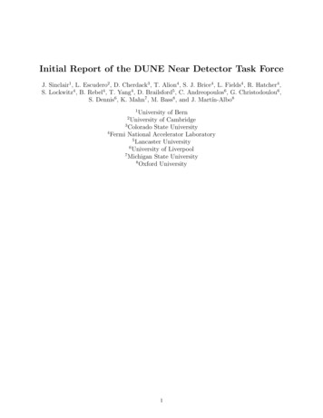
Cyclic Loading ProtocolShear Force-Displacement Behaviorof T-Joint SpecimensACI 349-06Specimen JS-T1-FSpecimen JS-T0-FSpecimen JS-T0-PSpecimen JS-T2-FShear Force-Displacement Behaviorof L-Joint Specimen
Crack pattern at the ultimate joint shear : all specimensJS-T1-FJS-T0-FJS-T0-PJS-T2-F
SC W ALL-TO-SLAB CONNECTIONSTypical SC Wall-to-RC Slab Connection
FORCE TRANSFER MECHANISMS
RESEARCH NEEDED TO COMPLETE DESIGN Out-of-planeshear and moment transfer mechanismneed experimental validation. There are no codes /standards for estimating the out-of-plane shearstrength of the wall-to-slab joint region. Experimentalverification of the wall-to-slab out-ofplane shear strength is needed.
MAJOR RESEARCH PRODUCT - 7 Twolarge-scale SC wall-to-RC slab specimens weretested to evaluate the out-of-plane moment transfermechanism, and out-of-plane shear strength Specimens were designed to develop the flexuralcapacity of the RC slab (using rebars).30 in.84 in.67.5 in.
MAJOR RESEARCH PRODUCT - 7Test SetupForce-Displacement
COMPLETE DESIGN EXAMPLE Appendix1 of the Design Guide includes a completedesign example with calculations, drawings, details etc. foran SC wall and corresponding basemat anchorageconnection
CONCLUSIONS Project AllGoal and Objectives were achievedproject tasks were completed successfully Severalmajor research products in terms of journalarticles, conference papers and presentation etc. Majoroutcomes include Ph.D. dissertations of twostudents. One working in INL now with structuralengineering and seismic group.
CONCLUSIONS Publishedconsensus code / standard from AISCN690s1 (2015), and AISC Design Guide (2016) for SCwalls Developedtwo different connection design philosophies DevelopedSC wall-to-basemat anchorage connectionsthat could achieve difference performance, and verifiedthem experimentally Developeddesign equations and approaches for anchorstrength needed to complete design
CONCLUSIONS Developeddesign approaches for SC wall-to-wallconnections including T-joints and L-joints Developedand verified equations for estimating thejoint shear strength of SC wall-to-wall joints Developed Developedand verified SC wall-to-RC slab connectionand published a complete design examplefor SC walls and connections
ACKNOWLEDGMENTS WestinghouseElectric Company TodBaker, Keith Coogler, Kai Zhang, BerndLaskewitz, Jurie Van Wyk, Michael Corletti Hirschfeld DOE-Industries, LLC for fabricating specimensNEUP Program
Seo et al. (2016) develop design equations for calculating the in-plane shear strength of SC walls with boundary elements and full-strength anchorage connections. SC W. ALL-TO-B. ASEMAT. A. NCHORAGE. C. ONNECTION. SC Wall- to-BasemaAt nchorage usng i. non-contact spliced rebars .