Transcription
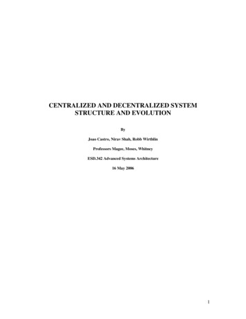
United StatesEnvironmental ProtectionAgencyOffice of WaterWashington, D.C.EPA 832-F 99-074September 1999Decentralized SystemsTechnology Fact SheetMound SystemsDESCRIPTIONThe mound system was originally developed inNorth Dakota in the late 1940s and called theNODAK disposal system. Some soil types areunsuitable for conventional septic tank soilabsorption systems. As a result, alternative systemssuch as the mound system can be used to overcomecertain soil and site conditions.The mound design in predominate use today wasmodified from the NODAK design by the Universityof Wisconsin-Madison in the early 1970s. Althoughthere are now many different mound designs in use,this fact sheet will focus on the Wisconsin design.The Wisconsin mound has been widely accepted andincorporated into many state regulations.The main purpose of a mound system is to providesufficient treatment to the natural environment toproduce an effluent equivalent to, or better than, aconventional onsite disposal system.ADVANTAGES AND DISADVANTAGESListed below are some advantages anddisadvantages of mound systems when compared toother alternative onsite systems.AdvantagesCThe mound system enables use of some sitesthat would otherwise be unsuitable forin-ground or at-grade onsite systems.CThe natural soil utilized in a mound system isthe upper most horizon, which is typically themost permeable.CA mound system does not have a directdischarge to a ditch, stream, or other body ofwater.Mounds are pressure-dosed sand filters thatdischarge directly to natural soil. They lie above thesoil surface and are designed to overcome siterestrictions such as:CConstruction damage is minimized since thereis little excavation required in the mound area.CMounds can be utilized in most climates.CSlow or fast permeability soils.DisadvantagesCShallow soil cover over creviced or porousbedrock.CCA high water table.The three principle components of a mound systemare a pretreatment unit(s), dosing chamber and theelevated mound. Figure 1 illustrates a Wisconsinmound system.APPLICABILITYConstruction costs are typically much higherthan conventional systems.
Source: Converse and Tyler, Copyright by the American Society of Agricultural Engineers, reprinted with permission, 1987.FIGURE 1 SCHEMATIC OF A WISCONSIN MOUND SYSTEMCCCC1) Leaving the topsoil in place but plowing itbefore placement of the fill.C2) Using a coarse sand fill meeting grain sizedistribution specifications.The location of the mound may affectdrainage patterns and limit land use options.C3) Using pressure to uniformly distribute theeffluent over the seepage area.The mound may have to be partially rebuilt ifseepage or leakage occurs.Soil DepthSince there is usually limited permeabletopsoil available at mound system sites.Extreme care must be taken not to damagethis layer with construction equipment.CAll systems require pumps or siphons.CMounds may not be aesthetically pleasing inunless properly landscaped.A suitable depth of soil is required to treat theeffluent before it reaches the limiting condition, suchas bedrock, a high water table, or a slowlypermeable soil layer. Although the separationdistance varies, it is usually between 1 and 4 feet.DESIGN CRITERIASite and DesignTwo factors that determine the size andconfiguration of a mound are; how the effluentmoves away and the rate at which it moves awayfrom the system. The prediction of the movementand rate of movement is done from studies of thesoil and site information obtained. To ensure properperformance of the mound system, the followingconcepts must be included in the design andconstruction process:To date, siting and design experience at sitessuitable for mound systems indicates that absorptionsystems should be long and narrow and shouldfollow the contour (i.e., level). The more restrictivethe site, the narrower and longer the system. Table1 gives the soil criteria for a Wisconsin moundbased on research and field experience.
TABLE 1 RECOMMENDED SOIL ANDSITE CRITERIA FOR THE WISCONSINMOUND SYSTEM BASED ONRESEARCH AND FIELD EXPERIENCEParameterValueDepth of high water table(permanent or seasonal)10 in.Depth to crevice bedrock2 ft.Depth to non-crevice bedrock1 ft.Permeability of top 10 in.Moderately lowSite slope25%Filled siteYesaOver old systemYesbFlood plainsNoa Suitable according to soil criteria (texture, structure,consistence).b The area and backfill must be treated as fill because itis a disturbed site.Source: Converse and Tyler, 1990.High WaterThe high water table is determined by directobservation (soil boring), interpretation of soilmottling, or other criteria. The bedrock should beclassified as crevice, non-crevice semi-permeable, ornon-crevice impermeable. This will determine thedepth of sand media required.Percolation and LoadingPercolation tests are used in some jurisdictions toestimate the soil permeability because they areempirically related to the loading rate. Loadingrates should be based on the soil texture, structure,and consistence, using the percolation test only toconfirm morphological interpretations.MoundsMounds can be constructed on sites with slopes upto 25%. The slope limitation is primarily forconstruction safety, because it is difficult to operateequipment on steep slopes, and they pose aconstruction hazard. From a hydraulic perspective,mounds can be positioned on steep slopes.SitesIn the case of filled sites, fill material is placed ontop of the natural soil and may consist of soiltextures ranging from sand to clay. Sufficient timemust be allowed for the soil structure to stabilizebefore constructing a system. Many moreobservations are required for filled areas.When evaluating the soil loading rate for a moundover an old or failing in-ground system, the soil overthe system must be considered to be disturbed, andthus, treated as a filled site. If a mound is to beplaced over a large in-ground system, a detailedevaluation of the effluent movement should be done.Mounds should not be installed in flood plains,drainage ways, or depressions unless floodprotection is provided. Another siting considerationis maintaining the horizontal separation distancesfrom water supply wells, surface waters, springs,escarpments, cuts, the boundary of the property,and the building foundation. Sites with trees andlarge boulders can make it difficult in preparing thesite. Trees should be cut to the ground surface withtilling around stumps. The size of the mound shouldbe increased to provide sufficient soil to accept theeffluent when trees and boulders occupy asignificant amount of the surface area.The actual size of a mound system is determined byestimating the sand fill loading rate, soil (basal)loading rate, and the linear loading rate. Once thesevalues are established, the mound can be sized forthe site. The final step is to design the effluentdistribution network and the pumping system.PERFORMANCEOne factor that determines good performance is thetype of sand fill material. A suitable sand is one thatcan adequately treat the wastewater. Suitable sandshould contain 20% or less material greater than 2.0mm and 5% or less finer than 0.053 mm. It shouldalso have a size distribution that meets certain sieveanalysis specifications, ASTMC-33 specifications,or meets limits for effective diameter and coefficientof uniformity.
For design of residential mounds, the dailywastewater volume is determined by the number ofbedrooms in a house. Typical design flowrequirements for individual homes are up to 150gallons per day (gpd) per bedroom. Designspecifications for mound systems are usually thesame for both large and small flows for typicaldomestic septic tank effluent. Higher strengthwastes must be pretreated to the levels of domesticseptic tank effluent, or lower hydraulic loading ratesmay be applied.The sites selected for this study had to fit theobjectives of the research and generate a reasonableamount of wastewater to be mound treated. Thesites selected had to have:1.Fill soil placed over natural soil.2.A high water table where the seasonal highwater table level was less than 60 cm belowthe ground surface.3.Slowly permeable soils that were ratedslower than moderately permeable soils.In Wisconsin, the success rate of the mound systemis over 95%, which is due to their emphasis onsiting, design, construction and maintenance.4.Steep slopes greater than 12%.5.Mounds over existing failing systems.Years of monitoring the performance of moundsystems have shown that mounds can consistentlyand effectively treat and dispose of wastewater.Studies have shown evidence that some nitrogenremoval does occur in mound systems whenapproximately 2 feet of natural unsaturated soil isbelow the fill material.6.A combination of the above.IMPLEMENTATIONMound Systems in Wisconsin (State-Wide)Using relatively conservative soil criteria, manystates have accepted the Wisconsin mound systemas an alternative when conventional in-groundtrenches and beds are not suitable. The Wisconsinmound system has evolved into a viable onsitesystem for the treatment of wastewater fromindividual, commercial, and community systems byovercoming some of the site limitations and meetingcode requirements and guidelines.In 1978, an experimental study was initiated toevaluate soil/site limitations for the Wisconsinmound (see Converse and Tyler, 1987a). Theobjectives of this research study were to determinewhether the existing soil/site limitations on moundswere too restrictive and to determine the minimumsoil/site limitations under which the mounds wouldperform without affecting public health and theenvironment. The experimental approach was todesign, construct, and evaluate sites with moundsystems that currently did not meet coderequirements due to failing systems.Over 40 experimental mounds were constructedbetween 1979 and 1983 on sites that did not meetthe code requirements; 11 of these mounds aredescribed in detail in this study. Site evaluationswere done by certified soil scientists, plans preparedby designers were reviewed and approved by thestate, and licensed contractors installed the systemswith inspections by county sanitarians duringconstruction.The study concluded that the overall performance ofthe mounds was very good. The systems functionedsatisfactory on filled sites, on sites with a high watertable (seasonal water table 25 to 30 cm from theground surface), on steep slope sites (up to 20 to25%), on sites with slowly permeable soil, and ontop of failing systems. Leakage occurred at the baseof the mound on some sites during extremely wetconditions, but the effluent quality was good, withfecal counts generally less than 10 colonies per 100ml in saturated toe effluent. It was found thatWisconsin mound systems can be constructed ondifficult sites if the system is designed using linearloading rates, which are established based on thehorizontal and vertical acceptance rates of the soilfor each system.
Failure of Mound System in WisconsinExpansion of a Wisconsin firm's mound system in1978, resulted in a clogging and seepage problem.The system was originally built to handle 65employees at 750 gpd and was now serving a staffof 165. This expansion created a failure of themound system due to hydraulic overload. To solvethis problem, the mound system was expanded anda water conservation program was initiated. Theexpansion of the mound increased the hydrauliccapacity to 2,600 gpd (Otis, 1981.)In general, the maintenance required for mounds isminimal. However, as with any system, poormaintenance could lead to early system failure.Possible problems that can occur in an improperlydesigned or constructed mound system include:CPonding in the absorption area of the mound.CSeepage out of the side or toe of the mound.CSpongy areas developing on the side, top, ortoe of the moundIn November 1979, the mound system failedagain—this time due to a biological clogging mat.The clogging mat was removed by using 450 gallonsof a 10% solution of hydrogen peroxide. Themound system was operating successfully within 2days. However, further research indicates that forstructured natural soils other than sand, hydrogenperoxide may reduce the soil infiltration rate, andthus, may not be an effective procedure to eliminatesoil clogging.CClogging of the distribution system.A third failure occurred in January 1980, again dueto hydraulic overload. The firm had expanded itsemployee base to 215 employees, with an averagedaily flow of 3,000 gpd. There was no roomavailable to expand the mound system itself, so thefirm redesigned the pumping chamber to avoid largepeak flows, allowing the mound system to receiveoptimum dosing without failure.Practices that can be used to reduce the possibilityof failure in a mound system include:CInstalling water-saving devices to reduce thehydraulic overload to the system.CCalibrating pumps and utilizing eventcounters and running time meters.CTimed dosing to dose equally sized doses onregular intervals throughout the day.CDiverting surface water and roof drainageaway from the mound.CPreventing traffic on the mound area.CInstalling inspection tubes in the mound tocheck for ponding.CKeeping deep-rooted plants (shrubs and trees)off the mound.CPlanting and maintaining grass or othervegetative cover on the mound surface toprevent erosion and to maximize wateruptake.CStand-by power for the pump.OPERATION AND MAINTENANCEThe septic tank and dosing chamber should bechecked for sludge and scum buildup and pumpedas needed to avoid carryover of solids into themound. Screens or filters can be used to preventlarge solids from escaping the septic tank. Thedosing chamber, pump, and floats should bechecked annually and replaced or repaired asnecessary. It is critical that the septic tank anddosing chamber be watertight.In addition,electrical parts and conduits must be checked forcorrosion. Flushing of the laterals annually isrecommended.When a mound system is properly installed andmaintained, it should last for a long period of time.Follow all instructions recommended by themanufacturer. All equipment must be tested andcalibrated as recommended by the equipmentmanufacturer. A routine operation and maintenance(O&M) schedule should be developed and followed
for any mound system in addition to checking localcodes.REFERENCES1.Converse, J. C. and E. J. Tyler. 1987a.On-Site Wastewater Treatment UsingWisconsin Mounds on Difficult Sites.Transactions of the ASAE. 1987. AmericanSociety of Agricultural Engineers. vol. 30.no. 2. pp. 362–368.2.Converse, J. C. and E. J. Tyler. 1987b.Inspecting and Trouble Shooting WisconsinMounds. Small Scale Waste ManagementProject. University of Wisconsin-Madison.Madison, Wisconsin.3.Converse, J. C. and E. J. Tyler. January1990. Wisconsin Mound Soil AbsorptionSystem Siting, Design, and ConstructionManual. Small Scale Waste ManagementProject. University of Wisconsin-Madison.Madison, Wisconsin.4.Otis, R. J. 1981. Rehabilitation of a MoundSystem. On-Site Sewage Treatment:Proceedings of the Third NationalSymposium on Individual and SmallCommunity Sewage Treatment. AmericanSociety of Agricultural Engineers. St.Joseph, Michigan.5.U.S. Environmental Protection Agency(EPA). 1980. Design Manual: OnsiteWastewater Treatment and DisposalSystems. EPA 625/1-80-012, EPA Office ofWater. EPA Municipal EnvironmentalResearch Laboratory. Cincinnati, Ohio.COSTSThe cost of a mound system is dependent on designcosts, energy costs, the contractor used, themanufacturers, land, and the characteristics of thewastewater. Table 2 lists some typical capital andO&M costs for a mound system serving athree-bedroom single home at a flow rate of 450gpd (150 gallons per bedroom). Septic tank costswere estimated at 1 per treated gallon. It should benoted however, that costs will vary from site to site.To keep construction costs to a minimum, use goodquality and local materials, when available.TABLE 2 TYPICAL COST ESTIMATE FORA MOUND SYSTEM (SINGLE HOME)ItemCost ( )Capital CostsConstruction CostsSeptic tank (1000 gallonconcrete tank)1,000Dosing chamber (includespump and controls)2,000Mound structure6,000Total Construction Costs9.000Non-Component CostsSite evaluation500Permits250Total Costs9,750ADDITIONAL INFORMATIONAnnual O&M CostsLabor @ 20/hr.20 per yearPower @8 cents/kWh35 per yearSeptic tank pumping75 to 150 every 3yearsSource: Ayres Associates, Inc., 1997.Mr. Richard J. Otis, Ph.D., P.E., DEEAyres Associates2445 Darwin RoadMadison, WI 53704-3186National Small Flows Clearing House atWest Virginia UniversityP.O. Box 6064Morgantown, WV 26506
The mention of trade names or commercial productsdoes not constitute endorsement or recommendationfor use by the U.S. Environmental ProtectionAgency.For more information contact:Municipal Technology BranchU.S. EPAMail Code 4204401 M St., S.W.Washington, D.C., 20460
The Wisconsin mound has been widely accepted and incorporated into many state regulations. The three principle components of a mound system are a pretreatment unit(s), dosing chamber and the elevated mound. Figure 1 illustrates a Wisconsin mound system. APPLICABILITY Mounds are pressure-dosed sand filters that discharge directly to natural soil.