Transcription
ModelSim TutorialSoftware Version 6.4a 1991-2008 Mentor Graphics CorporationAll rights reserved.This document contains information that is proprietary to Mentor Graphics Corporation. The original recipient of thisdocument may duplicate this document in whole or in part for internal business purposes only, provided that this entirenotice appears in all copies. In duplicating any part of this document, the recipient agrees to make every reasonableeffort to prevent the unauthorized use and distribution of the proprietary information.
This document is for information and instruction purposes. Mentor Graphics reserves the right to makechanges in specifications and other information contained in this publication without prior notice, and thereader should, in all cases, consult Mentor Graphics to determine whether any changes have beenmade.The terms and conditions governing the sale and licensing of Mentor Graphics products are set forth inwritten agreements between Mentor Graphics and its customers. No representation or other affirmationof fact contained in this publication shall be deemed to be a warranty or give rise to any liability of MentorGraphics whatsoever.MENTOR GRAPHICS MAKES NO WARRANTY OF ANY KIND WITH REGARD TO THIS MATERIALINCLUDING, BUT NOT LIMITED TO, THE IMPLIED WARRANTIES OF MERCHANTABILITY ANDFITNESS FOR A PARTICULAR PURPOSE.MENTOR GRAPHICS SHALL NOT BE LIABLE FOR ANY INCIDENTAL, INDIRECT, SPECIAL, ORCONSEQUENTIAL DAMAGES WHATSOEVER (INCLUDING BUT NOT LIMITED TO LOST PROFITS)ARISING OUT OF OR RELATED TO THIS PUBLICATION OR THE INFORMATION CONTAINED IN IT,EVEN IF MENTOR GRAPHICS CORPORATION HAS BEEN ADVISED OF THE POSSIBILITY OFSUCH DAMAGES.RESTRICTED RIGHTS LEGEND 03/97U.S. Government Restricted Rights. The SOFTWARE and documentation have been developed entirelyat private expense and are commercial computer software provided with restricted rights. Use,duplication or disclosure by the U.S. Government or a U.S. Government subcontractor is subject to therestrictions set forth in the license agreement provided with the software pursuant to DFARS 227.72023(a) or as set forth in subparagraph (c)(1) and (2) of the Commercial Computer Software - RestrictedRights clause at FAR 52.227-19, as applicable.Contractor/manufacturer is:Mentor Graphics Corporation8005 S.W. Boeckman Road, Wilsonville, Oregon 97070-7777.Telephone: 503.685.7000Toll-Free Telephone: 800.592.2210Website: www.mentor.comTRADEMARKS: The trademarks, logos and service marks ("Marks") used herein are the property ofMentor Graphics Corporation or other third parties. No one is permitted to use these Marks without theprior written consent of Mentor Graphics or the respective third-party owner. The use herein of a thirdparty Mark is not an attempt to indicate Mentor Graphics as a source of a product, but is intended toindicate a product from, or associated with, a particular third party. A current list of Mentor Graphics’trademarks may be viewed at: www.mentor.com/terms conditions/trademarks.cfm.
Table of ContentsChapter 1Introduction. . . . . . . . . . . . . . . . . . . . . . . . . . . . . . . . . . . . . . . . . . . . . . . . . . . . . . . . . . . . . . .Assumptions. . . . . . . . . . . . . . . . . . . . . . . . . . . . . . . . . . . . . . . . . . . . . . . . . . . . . . . . . . . . . .Before you Begin . . . . . . . . . . . . . . . . . . . . . . . . . . . . . . . . . . . . . . . . . . . . . . . . . . . . . . . . . .Example Designs . . . . . . . . . . . . . . . . . . . . . . . . . . . . . . . . . . . . . . . . . . . . . . . . . . . . . . . .9999Chapter 2Conceptual Overview . . . . . . . . . . . . . . . . . . . . . . . . . . . . . . . . . . . . . . . . . . . . . . . . . . . . . . .Basic Simulation Flow. . . . . . . . . . . . . . . . . . . . . . . . . . . . . . . . . . . . . . . . . . . . . . . . . . . . . .Project Flow . . . . . . . . . . . . . . . . . . . . . . . . . . . . . . . . . . . . . . . . . . . . . . . . . . . . . . . . . . . . . .Multiple Library Flow . . . . . . . . . . . . . . . . . . . . . . . . . . . . . . . . . . . . . . . . . . . . . . . . . . . . . .Debugging Tools . . . . . . . . . . . . . . . . . . . . . . . . . . . . . . . . . . . . . . . . . . . . . . . . . . . . . . . . . .1111121314Chapter 3Basic Simulation . . . . . . . . . . . . . . . . . . . . . . . . . . . . . . . . . . . . . . . . . . . . . . . . . . . . . . . . . . .Create the Working Design Library. . . . . . . . . . . . . . . . . . . . . . . . . . . . . . . . . . . . . . . . . . . .Run the Simulation . . . . . . . . . . . . . . . . . . . . . . . . . . . . . . . . . . . . . . . . . . . . . . . . . . . . . . . .Set Breakpoints and Step through the Source . . . . . . . . . . . . . . . . . . . . . . . . . . . . . . . . . . . .Navigating the Interface. . . . . . . . . . . . . . . . . . . . . . . . . . . . . . . . . . . . . . . . . . . . . . . . . . . . .1516202225Chapter 4Projects. . . . . . . . . . . . . . . . . . . . . . . . . . . . . . . . . . . . . . . . . . . . . . . . . . . . . . . . . . . . . . . . . . .Create a New Project . . . . . . . . . . . . . . . . . . . . . . . . . . . . . . . . . . . . . . . . . . . . . . . . . . . . . . .Add Objects to the Project . . . . . . . . . . . . . . . . . . . . . . . . . . . . . . . . . . . . . . . . . . . . . . . . .Changing Compile Order (VHDL) . . . . . . . . . . . . . . . . . . . . . . . . . . . . . . . . . . . . . . . . . . .Compile the Design. . . . . . . . . . . . . . . . . . . . . . . . . . . . . . . . . . . . . . . . . . . . . . . . . . . . . . .Load the Design . . . . . . . . . . . . . . . . . . . . . . . . . . . . . . . . . . . . . . . . . . . . . . . . . . . . . . . . .Organizing Projects with Folders. . . . . . . . . . . . . . . . . . . . . . . . . . . . . . . . . . . . . . . . . . . . . .Add Folders. . . . . . . . . . . . . . . . . . . . . . . . . . . . . . . . . . . . . . . . . . . . . . . . . . . . . . . . . . . . .Moving Files to Folders . . . . . . . . . . . . . . . . . . . . . . . . . . . . . . . . . . . . . . . . . . . . . . . . . . .Simulation Configurations . . . . . . . . . . . . . . . . . . . . . . . . . . . . . . . . . . . . . . . . . . . . . . . . . . .31313234353637373939Chapter 5Working With Multiple Libraries. . . . . . . . . . . . . . . . . . . . . . . . . . . . . . . . . . . . . . . . . . . . .Creating the Resource Library . . . . . . . . . . . . . . . . . . . . . . . . . . . . . . . . . . . . . . . . . . . . . . . .Creating the Project . . . . . . . . . . . . . . . . . . . . . . . . . . . . . . . . . . . . . . . . . . . . . . . . . . . . . . . .Linking to the Resource Library . . . . . . . . . . . . . . . . . . . . . . . . . . . . . . . . . . . . . . . . . . . . . .Linking in Verilog. . . . . . . . . . . . . . . . . . . . . . . . . . . . . . . . . . . . . . . . . . . . . . . . . . . . . . . .Linking in VHDL . . . . . . . . . . . . . . . . . . . . . . . . . . . . . . . . . . . . . . . . . . . . . . . . . . . . . . . .Permanently Mapping VHDL Resource Libraries . . . . . . . . . . . . . . . . . . . . . . . . . . . . . . . .43434546484951ModelSim Tutorial, v6.4a3
Table of ContentsChapter 6Analyzing Waveforms . . . . . . . . . . . . . . . . . . . . . . . . . . . . . . . . . . . . . . . . . . . . . . . . . . . . . .Loading a Design . . . . . . . . . . . . . . . . . . . . . . . . . . . . . . . . . . . . . . . . . . . . . . . . . . . . . . . . . .Add Objects to the Wave Window . . . . . . . . . . . . . . . . . . . . . . . . . . . . . . . . . . . . . . . . . . . .Zooming the Waveform Display . . . . . . . . . . . . . . . . . . . . . . . . . . . . . . . . . . . . . . . . . . . . . .Using Cursors in the Wave Window . . . . . . . . . . . . . . . . . . . . . . . . . . . . . . . . . . . . . . . . . . .Working with a Single Cursor . . . . . . . . . . . . . . . . . . . . . . . . . . . . . . . . . . . . . . . . . . . . . .Working with Multiple Cursors . . . . . . . . . . . . . . . . . . . . . . . . . . . . . . . . . . . . . . . . . . . . .53545455565658Chapter 7Viewing And Initializing Memories . . . . . . . . . . . . . . . . . . . . . . . . . . . . . . . . . . . . . . . . . . .View a Memory and its Contents. . . . . . . . . . . . . . . . . . . . . . . . . . . . . . . . . . . . . . . . . . . . . .Navigate Within the Memory . . . . . . . . . . . . . . . . . . . . . . . . . . . . . . . . . . . . . . . . . . . . . . .Export Memory Data to a File . . . . . . . . . . . . . . . . . . . . . . . . . . . . . . . . . . . . . . . . . . . . . . . .Initialize a Memory . . . . . . . . . . . . . . . . . . . . . . . . . . . . . . . . . . . . . . . . . . . . . . . . . . . . . . . .Interactive Debugging Commands . . . . . . . . . . . . . . . . . . . . . . . . . . . . . . . . . . . . . . . . . . . .616265676972Chapter 8Automating Simulation . . . . . . . . . . . . . . . . . . . . . . . . . . . . . . . . . . . . . . . . . . . . . . . . . . . . .Creating a Simple DO File. . . . . . . . . . . . . . . . . . . . . . . . . . . . . . . . . . . . . . . . . . . . . . . . . . .Running in Command-Line Mode . . . . . . . . . . . . . . . . . . . . . . . . . . . . . . . . . . . . . . . . . . . . .Using Tcl with the Simulator. . . . . . . . . . . . . . . . . . . . . . . . . . . . . . . . . . . . . . . . . . . . . . . . .77777881IndexEnd-User License Agreement4ModelSim Tutorial, v6.4a
List of Examples5ModelSim Tutorial, v6.4a
List of FiguresFigure 2-1. Basic Simulation Flow - Overview Lab . . . . . . . . . . . . . . . . . . . . . . . . . . . . . . .Figure 2-2. Project Flow . . . . . . . . . . . . . . . . . . . . . . . . . . . . . . . . . . . . . . . . . . . . . . . . . . . .Figure 2-3. Multiple Library Flow. . . . . . . . . . . . . . . . . . . . . . . . . . . . . . . . . . . . . . . . . . . . .Figure 3-1. Basic Simulation Flow - Simulation Lab . . . . . . . . . . . . . . . . . . . . . . . . . . . . . .Figure 3-2. The Create a New Library Dialog. . . . . . . . . . . . . . . . . . . . . . . . . . . . . . . . . . . .Figure 3-3. work Library in the Workspace. . . . . . . . . . . . . . . . . . . . . . . . . . . . . . . . . . . . . .Figure 3-4. Compile Source Files Dialog . . . . . . . . . . . . . . . . . . . . . . . . . . . . . . . . . . . . . . .Figure 3-5. Verilog Modules Compiled into work Library . . . . . . . . . . . . . . . . . . . . . . . . . .Figure 3-6. Loading Design with Start Simulation Dialog . . . . . . . . . . . . . . . . . . . . . . . . . .Figure 3-7. Workspace sim Tab Displays Design Hierarchy . . . . . . . . . . . . . . . . . . . . . . . .Figure 3-8. Object Pane Displays Design Objects. . . . . . . . . . . . . . . . . . . . . . . . . . . . . . . . .Figure 3-9. Using the Popup Menu to Add Signals to Wave Window . . . . . . . . . . . . . . . . .Figure 3-10. Waves Drawn in Wave Window. . . . . . . . . . . . . . . . . . . . . . . . . . . . . . . . . . . .Figure 3-11. Setting Breakpoint in Source Window . . . . . . . . . . . . . . . . . . . . . . . . . . . . . . .Figure 3-12. Setting Restart Functions . . . . . . . . . . . . . . . . . . . . . . . . . . . . . . . . . . . . . . . . .Figure 3-13. Blue Arrow Indicates Where Simulation Stopped. . . . . . . . . . . . . . . . . . . . . . .Figure 3-14. Values Shown in Objects Window . . . . . . . . . . . . . . . . . . . . . . . . . . . . . . . . . .Figure 3-15. Parameter Name and Value in Source Examine Window . . . . . . . . . . . . . . . .Figure 3-16. The Main Window . . . . . . . . . . . . . . . . . . . . . . . . . . . . . . . . . . . . . . . . . . . . . .Figure 3-17. Window/Pane Control Icons . . . . . . . . . . . . . . . . . . . . . . . . . . . . . . . . . . . . . . .Figure 3-18. zooming in on Workspace Pane . . . . . . . . . . . . . . . . . . . . . . . . . . . . . . . . . . . .Figure 3-19. Panes Rearranged in Main Window . . . . . . . . . . . . . . . . . . . . . . . . . . . . . . . . .Figure 4-1. Create Project Dialog - Project Lab . . . . . . . . . . . . . . . . . . . . . . . . . . . . . . . . . .Figure 4-2. Adding New Items to a Project . . . . . . . . . . . . . . . . . . . . . . . . . . . . . . . . . . . . . .Figure 4-3. Add file to Project Dialog . . . . . . . . . . . . . . . . . . . . . . . . . . . . . . . . . . . . . . . . . .Figure 4-4. Newly Added Project Files Display a “?” for Status . . . . . . . . . . . . . . . . . . . . .Figure 4-5. Compile Order Dialog. . . . . . . . . . . . . . . . . . . . . . . . . . . . . . . . . . . . . . . . . . . . .Figure 4-6. Library Tab with Expanded Library . . . . . . . . . . . . . . . . . . . . . . . . . . . . . . . . . .Figure 4-7. Structure Tab for a Loaded Design . . . . . . . . . . . . . . . . . . . . . . . . . . . . . . . . . . .Figure 4-8. Adding New Folder to Project . . . . . . . . . . . . . . . . . . . . . . . . . . . . . . . . . . . . . .Figure 4-9. A Folder Within a Project . . . . . . . . . . . . . . . . . . . . . . . . . . . . . . . . . . . . . . . . . .Figure 4-10. Creating Subfolder . . . . . . . . . . . . . . . . . . . . . . . . . . . . . . . . . . . . . . . . . . . . . .Figure 4-11. A folder with a Sub-folder . . . . . . . . . . . . . . . . . . . . . . . . . . . . . . . . . . . . . . . .Figure 4-12. Changing File Location via the Project Compiler Settings Dialog. . . . . . . . . .Figure 4-13. Simulation Configuration Dialog . . . . . . . . . . . . . . . . . . . . . . . . . . . . . . . . . . .Figure 4-14. A Simulation Configuration in the Project Tab . . . . . . . . . . . . . . . . . . . . . . . .Figure 4-15. Transcript Shows Options for Simulation Configurations . . . . . . . . . . . . . . . .Figure 5-1. Creating New Resource Library . . . . . . . . . . . . . . . . . . . . . . . . . . . . . . . . . . . . .Figure 5-2. Compiling into the Resource Library . . . . . . . . . . . . . . . . . . . . . . . . . . . . . . . . .Figure 5-3. Verilog Simulation Error Reported in Main Window. . . . . . . . . . . . . . . . . . . . 33343536363738383839404141444547ModelSim Tutorial, v6.4a
List of FiguresFigure 5-4. VHDL Simulation Warning Reported in Main Window . . . . . . . . . . . . . . . . . .Figure 5-5. Specifying a Search Library in the Simulate Dialog. . . . . . . . . . . . . . . . . . . . . .Figure 5-6. Mapping to the parts lib Library . . . . . . . . . . . . . . . . . . . . . . . . . . . . . . . . . . . .Figure 5-7. Adding LIBRARY and USE Statements to the Testbench. . . . . . . . . . . . . . . . .Figure 6-1. Panes of the Wave Window . . . . . . . . . . . . . . . . . . . . . . . . . . . . . . . . . . . . . . . .Figure 6-2. Undocking the Wave Window . . . . . . . . . . . . . . . . . . . . . . . . . . . . . . . . . . . . . .Figure 6-3. Zooming in with the Mouse Pointer . . . . . . . . . . . . . . . . . . . . . . . . . . . . . . . . . .Figure 6-4. Working with a Single Cursor in the Wave Window . . . . . . . . . . . . . . . . . . . . .Figure 6-5. Renaming a Cursor . . . . . . . . . . . . . . . . . . . . . . . . . . . . . . . . . . . . . . . . . . . . . . .Figure 6-6. Interval Measurement Between Two Cursors. . . . . . . . . . . . . . . . . . . . . . . . . . .Figure 6-7. A Locked Cursor in the Wave Window . . . . . . . . . . . . . . . . . . . . . . . . . . . . . . .Figure 7-1. Viewing the Memories Tab in the Main Window Workspace . . . . . . . . . . . . . .Figure 7-2. The mem Tab in the MDI Frame Shows Addresses and Data . . . . . . . . . . . . . .Figure 7-3. The Memory Display Updates with the Simulation . . . . . . . . . . . . . . . . . . . . . .Figure 7-4. Changing the Address Radix. . . . . . . . . . . . . . . . . . . . . . . . . . . . . . . . . . . . . . . .Figure 7-5. New Address Radix and Line Length . . . . . . . . . . . . . . . . . . . . . . . . . . . . . . . . .Figure 7-6. Goto Dialog. . . . . . . . . . . . . . . . . . . . . . . . . . . . . . . . . . . . . . . . . . . . . . . . . . . . .Figure 7-7. Editing the Address Directly. . . . . . . . . . . . . . . . . . . . . . . . . . . . . . . . . . . . . . . .Figure 7-8. Searching for a Specific Data Value . . . . . . . . . . . . . . . . . . . . . . . . . . . . . . . . . .Figure 7-9. Export Memory Dialog . . . . . . . . . . . . . . . . . . . . . . . . . . . . . . . . . . . . . . . . . . . .Figure 7-10. Import Memory Dialog . . . . . . . . . . . . . . . . . . . . . . . . . . . . . . . . . . . . . . . . . . .Figure 7-11. Initialized Memory from File and Fill Pattern . . . . . . . . . . . . . . . . . . . . . . . . .Figure 7-12. Data Increments Starting at Address 251 . . . . . . . . . . . . . . . . . . . . . . . . . . . . .Figure 7-13. Original Memory Content . . . . . . . . . . . . . . . . . . . . . . . . . . . . . . . . . . . . . . . . .Figure 7-14. Changing Memory Content for a Range of Addresses . . . . . . . . . . . . . . . . . . .Figure 7-15. Random Content Generated for a Range of Addresses. . . . . . . . . . . . . . . . . . .Figure 7-16. Changing Memory Contents by Highlighting. . . . . . . . . . . . . . . . . . . . . . . . . .Figure 7-17. Entering Data to Change . . . . . . . . . . . . . . . . . . . . . . . . . . . . . . . . . . . . . . . . . .Figure 7-18. Changed Memory Contents for the Specified Addresses . . . . . . . . . . . . . . . . .Figure 8-1. A Dataset in the Main Window Workspace . . . . . . . . . . . . . . . . . . . . . . . . . . . .ModelSim Tutorial, 2737374747575807
List of TablesTable 3-1. The Main Window . . . . . . . . . . . . . . . . . . . . . . . . . . . . . . . . . . . . . . . . . . . . . . . .ModelSim Tutorial, v6.4a268
Chapter 1IntroductionAssumptionsWe assume that you are familiar with the use of your operating system. You should also befamiliar with the window management functions of your graphic interface: OpenWindows,OSF/Motif, CDE, KDE, GNOME, or Microsoft Windows 2000/XP.We also assume that you have a working knowledge of the language in which your designand/or testbench is written (i.e., VHDL, Verilog, etc.). Although ModelSim is an excellenttool to use while learning HDL concepts and practices, this document is not written to supportthat goal.Before you BeginPreparation for some of the lessons leaves certain details up to you. You will decide the bestway to create directories, copy files, and execute programs within your operating system.(When you are operating the simulator within ModelSim’s GUI, the interface is consistent forall platforms.)Examples show Windows path separators - use separators appropriate for your operating systemwhen trying the examples.Example DesignsModelSim comes with Verilog and VHDL versions of the designs used in these lessons. Thisallows you to do the tutorial regardless of which license type you have. Though we have tried tominimize the differences between the Verilog and VHDL versions, we could not do so in allcases. In cases where the designs differ (e.g., line numbers or syntax), you will find languagespecific instructions. Follow the instructions that are appropriate for the language you use.ModelSim Tutorial, v6.4a9
IntroductionBefore you Begin10ModelSim Tutorial, v6.4a
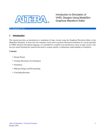
Chapter 2Conceptual OverviewIntroductionModelSim is a verification and simulation tool for VHDL, Verilog, SystemVerilog, and mixedlanguage designs.This lesson provides a brief conceptual overview of the ModelSim simulation environment. It isdivided into fourtopics, which you will learn more about in subsequent lessons. Basic simulation flow — Refer to Chapter 3 Basic Simulation. Project flow — Refer to Chapter 4 Projects. Multiple library flow — Refer to Chapter 5 Working With Multiple Libraries. Debugging tools — Refer to remaining lessons.Basic Simulation FlowThe following diagram shows the basic steps for simulating a design in ModelSim.Figure 2-1. Basic Simulation Flow - Overview LabCreate a working libraryCompile design filesLoad and Run simulationDebug results Creating the Working LibraryModelSim Tutorial, v6.4a11
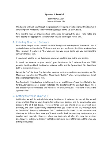
Conceptual OverviewProject FlowIn ModelSim, all designs are compiled into a library. You typically start a newsimulation in ModelSim by creating a working library called "work". "Work" is thelibrary name used by the compiler as the default destination for compiled design units. Compiling Your DesignAfter creating the working library, you compile your design units into it. The ModelSimlibrary format is compatible across all supported platforms. You can simulate yourdesign on any platform without having to recompile your design. Loading the Simulator with Your Design and Running the SimulationWith the design compiled, you load the simulator with your design by invoking thesimulator on a top-level module (Verilog) or a configuration or entity/architecture pair(VHDL).Assuming the design loads successfully, the simulation time is set to zero, and you entera run command to begin simulation. Debugging Your ResultsIf you don’t get the results you expect, you can use ModelSim’s robust debuggingenvironment to track down the cause of the problem.Project FlowA project is a collection mechanism for an HDL design under specification or test. Even thoughyou don’t have to use projects in ModelSim, they may ease interaction with the tool and areuseful for organizing files and specifying simulation settings.The following diagram shows the basic steps for simulating a design within a ModelSimproject.12ModelSim Tutorial, v6.4a
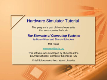
Conceptual OverviewMultiple Library FlowFigure 2-2. Project FlowCreate a projectAdd files to the projectCompile design filesRun simulationDebug resultsAs you can see, the flow is similar to the basic simulation flow. However, there are twoimportant differences: You do not have to create a working library in the project flow; it is done for youautomatically. Projects are persistent. In other words, they will open every time you invoke ModelSimunless you specifically close them.Multiple Library FlowModelSim uses libraries in two ways: 1) as a local working library that contains the compiledversion of your design; 2) as a resource library. The contents of your working library willchange as you update your design and recompile. A resource library is typically static andserves as a parts source for your design. You can create your own resource libraries, or theymay be supplied by another design team or a third party (e.g., a silicon vendor).You specify which resource libraries will be used when the design is compiled, and there arerules to specify in which order they are searched. A common example of using both a workinglibrary and a resource library is one where your gate-level design and testbench are compiledinto the working library, and the design references gate-level models in a separate resourcelibrary.The diagram below shows the basic steps for simulating with multiple libraries.ModelSim Tutorial, v6.4a13
Conceptual OverviewDebugging ToolsFigure 2-3. Multiple Library FlowCreate a working libraryCompile design filesLink to resource librariesRun simulationDebug resultsYou can also link to resource libraries from within a project. If you are using a project, youwould replace the first step above with these two steps: create the project and add the testbenchto the project.Debugging ToolsModelSim offers numerous tools for debugging and analyzing your design. Several of thesetools are covered in subsequent lessons, including:14 Using projects Working with multiple libraries Setting breakpoints and stepping through the source code Viewing waveforms and measuring time Viewing and initializing memories Creating stimulus with the Waveform Editor Automating simulationModelSim Tutorial, v6.4a
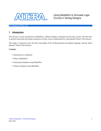
Chapter 3Basic SimulationIntroductionIn this lesson you will go step-by-step through the basic simulation flow:Figure 3-1. Basic Simulation Flow - Simulation LabCreate a working libraryCompile design unitsRun simulationDebug resultsDesign Files for this LessonThe sample design for this lesson is a simple 8-bit, binary up-counter with an associatedtestbench. The pathnames are as follows:Verilog – install dir r.v and tcounter.vVHDL – install dir hd and tcounter.vhdThis lesson uses the Verilog files counter.v and tcounter.v. If you have a VHDL license, usecounter.vhd and tcounter.vhd instead. Or, if you have a mixed license, feel free to use theVerilog testbench with the VHDL counter or vice versa.Related ReadingUser’s Manual Chapters: Design Libraries, Verilog and SystemVerilog Simulation, and VHDLSimulation.Reference Manual commands: vlib, vmap, vlog, vcom, view, and run.ModelSim Tutorial, v6.4a15
Basic SimulationCreate the Working Design LibraryCreate the Working Design LibraryBefore you can simulate a design, you must first create a library and compile the source codeinto that library.1. Create a new directory and copy the design files for this lesson into it.Start by creating a new directory for this exercise (in case other users will be workingwith these lessons).Verilog: Copy counter.v and tcounter.v files from/ install dir /examples/tutorials/verilog/basicSimulation to the new directory.VHDL: Copy counter.vhd and tcounter.vhd files from/ install dir /examples/tutorials/vhdl/basicSimulation to the new directory.2. Start ModelSim if necessary.a. Type vsim at a UNIX shell prompt or use the ModelSim icon in Windows.Upon opening ModelSim for the first time, you will see the Welcome to ModelSimdialog. Click Close.b. Select File Change Directory and change to the directory you created in step 1.3. Create the working library.a. Select File New Library.This opens a dialog where you specify physical and logical names for the library(Figure 3-2). You can create a new library or map to an existing library. We’ll bedoing the former.Figure 3-2. The Create a New Library Dialogb. Type work in the Library Name field (if it isn’t already entered automatically).16ModelSim Tutorial, v6.4a
Basic SimulationCreate the Working Design Libraryc. Click OK.ModelSim creates a directory called work and writes a specially-formatted filenamed info into that directory. The info file must remain in the directory todistinguish it as a ModelSim library. Do not edit the folder contents from youroperating system; all changes should be made from within ModelSim.ModelSim also adds the library to the list in the Workspace (Figure 3-3) and recordsthe library mapping for future reference in the ModelSim initialization file(modelsim.ini).Figure 3-3. work Library in the WorkspaceWhen you pressed OK in step 3c above, the following was printed to the Transcript:vlib workvmap work workThese two lines are the command-line equivalents of the menu selections you made. Manycommand-line equivalents will echo their menu-driven functions in this fashion.Compile the DesignWith the working library created, you are ready to compile your source files.You can compile by using the menus and dialogs of the graphic interface, as in the Verilogexample below, or by entering a command at the ModelSim prompt.1. Compile counter.v and tcounter.v.a. Select Compile Compile. This opens the Compile Source Files dialog(Figure 3-4).If the Compile menu option is not available, you probably have a project open. If so,close the project by making the Workspace pane active and selecting File Closefrom the menus.ModelSim Tutorial, v6.4a17
Basic SimulationCreate the Working Design Libraryb. Select both counter.v and tcounter.v modules from the Compile Source Files dialogand click Compile. The files are compiled into the work library.c. When compile is finished, click Done.Figure 3-4. Compile Source Files Dialog2. View the compiled design units.a. On the Library tab, click the ’ ’ icon next to the work library and you will see twodesign units (Figure 3-5). You can also see their types (Modules, Entities, etc.) andthe path to the underlying source files (scroll to the right if necessary).Figure 3-5. Verilog Modules Compiled into work LibraryLoad the Design1. Load the test counter module into the simulator.a. In the Workspace, click the ‘ ’ sign next to the work library to show the filescontained there.18ModelSim Tutorial, v6.4a
Basic SimulationCreate the Working Design Libraryb. Double-click test counter to load the design.You can also load the design by selecting Simulate Start Simulation in the menubar. This opens the Start Simulation dialog. With the Design tab selected, click the’ ’ sign next to the work library to see the counter and test counter modules. Selectthe test counter module and click OK (Figure 3-6).Figure 3-6. Loading Design with Start Simulation DialogWhen the design is loaded, you will see a new tab in the Workspace named sim thatdisplays the hierarchical structure of the design (Figure 3-7). You can navigatewithin the hierarchy by clicking on any line with a ’ ’ (expand) or ’-’ (contract)icon. You will also see a tab named Files that displays all files included in thedesign.ModelSim Tutorial, v6.4a19
Basic SimulationRun the SimulationFigure 3-7. Workspace sim Tab Displays Design Hierarchy2. View design objects in the Objects pane.a. Open the View menu and select Objects. The command line equivalent is:view objectsThe Objects pane (Figure 3-8) shows the names and current values of data objects inthe current region (selected in the Workspace). Data objects include signals, nets,registers, constants and variables not declared in a process, generics, parameters.Figure 3-8. Object Pane Displays Design ObjectsYou may open other windows and panes with the View menu or with the viewcommand. See Navigating the Interface.Run the SimulationNow you will open the Wave window, add signals to it, then run the simulation.1. Open the Wave debugging window.a. Enter view wave at the command line.20ModelSim Tutorial, v6.4a
Basic SimulationRun the SimulationYou can also use the View Wave menu selection to open a Wave window.The Wave window is one of several windows available for debugging. To see a listof the other debugging wind
ModelSim comes with Verilog and VHDL versions of the designs used in these lessons. This allows you to do the tutorial regardless of which license type you have. Though we have tried to minimize the differences between the Verilog and