Transcription
53-1002817-0224 June 2013Brocade ICX 6430-CCompact SwitchHardware Installation GuideSupporting software release 08.0.00a on device models ICX 6430-C12
Copyright 2013 Brocade Communications Systems, Inc. All Rights Reserved.Brocade, Brocade Assurance, the B-wing symbol, BigIron, DCX, Fabric OS, FastIron, MLX, NetIron, SAN Health, ServerIron,TurboIron, VCS, and VDX are registered trademarks, and AnyIO, Brocade One, CloudPlex, Effortless Networking, ICX, NET Health,OpenScript, and The Effortless Network are trademarks of Brocade Communications Systems, Inc., in the United States and/or inother countries. Other brands, products, or service names mentioned may be trademarks of their respective owners.Notice: This document is for informational purposes only and does not set forth any warranty, expressed or implied, concerningany equipment, equipment feature, or service offered or to be offered by Brocade. Brocade reserves the right to make changes tothis document at any time, without notice, and assumes no responsibility for its use. This informational document describesfeatures that may not be currently available. Contact a Brocade sales office for information on feature and product availability.Export of technical data contained in this document may require an export license from the United States government.The authors and Brocade Communications Systems, Inc. shall have no liability or responsibility to any person or entity withrespect to any loss, cost, liability, or damages arising from the information contained in this book or the computer programs thataccompany it.The product described by this document may contain “open source” software covered by the GNU General Public License or otheropen source license agreements. To find out which open source software is included in Brocade products, view the licensingterms applicable to the open source software, and obtain a copy of the programming source code, please visithttp://www.brocade.com/support/oscd.Brocade Communications Systems, IncorporatedCorporate and Latin American HeadquartersBrocade Communications Systems, Inc.130 Holger WaySan Jose, CA 95134Tel: 1-408-333-8000Fax: 1-408-333-8101E-mail: info@brocade.comAsia-Pacific HeadquartersBrocade Communications Systems China HK, Ltd.No. 1 Guanghua RoadChao Yang DistrictUnits 2718 and 2818Beijing 100020, ChinaTel: 8610 6588 8888Fax: 8610 6588 9999E-mail: china-info@brocade.comEuropean HeadquartersBrocade Communications Switzerland SàrlCentre SwissairTour B - 4ème étage29, Route de l'AéroportCase Postale 105CH-1215 Genève 15SwitzerlandTel: 41 22 799 5640Fax: 41 22 799 5641E-mail: emea-info@brocade.comAsia-Pacific HeadquartersBrocade Communications Systems Co., Ltd. (Shenzhen WFOE)Citic PlazaNo. 233 Tian He Road NorthUnit 1308 – 13th FloorGuangzhou, ChinaTel: 8620 3891 2000Fax: 8620 3891 2111E-mail: china-info@brocade.comDocument HistoryTitlePublication numberSummary of changesDateBrocade ICX 6430-C Compact SwitchHardware Installation Guide53-1002817-01New documentApril 2013Brocade ICX 6430-C Compact SwitchHardware Installation Guide53-1002817-02Updated withenhancements in Release08.0.00aJune 2013
ContentsAbout This DocumentHow this document is organized . . . . . . . . . . . . . . . . . . . . . . . . . . . . viiSupported hardware and software . . . . . . . . . . . . . . . . . . . . . . . . . . viiiDocument conventions . . . . . . . . . . . . . . . . . . . . . . . . . . . . . . . . . . . . viiiText formatting . . . . . . . . . . . . . . . . . . . . . . . . . . . . . . . . . . . . . . . viiiCommand syntax conventions . . . . . . . . . . . . . . . . . . . . . . . . . . viiiCommand examples . . . . . . . . . . . . . . . . . . . . . . . . . . . . . . . . . . . ixNotes, cautions, and warnings . . . . . . . . . . . . . . . . . . . . . . . . . . . ixNotice to the reader . . . . . . . . . . . . . . . . . . . . . . . . . . . . . . . . . . . . . . . ixAdditional information. . . . . . . . . . . . . . . . . . . . . . . . . . . . . . . . . . . . . . xBrocade resources . . . . . . . . . . . . . . . . . . . . . . . . . . . . . . . . . . . . . xGetting technical help or reporting errors . . . . . . . . . . . . . . . . . . . . . . xDocument feedback . . . . . . . . . . . . . . . . . . . . . . . . . . . . . . . . . . . . . . . xChapter 1ICX 6430-C Product OverviewHardware features . . . . . . . . . . . . . . . . . . . . . . . . . . . . . . . . . . . . . . . . 1ICX 6430-C models . . . . . . . . . . . . . . . . . . . . . . . . . . . . . . . . . . . . 1Network and management interfaces . . . . . . . . . . . . . . . . . . . . . . . . . 2Console management interface . . . . . . . . . . . . . . . . . . . . . . . . . . 2Out-of-band management interface . . . . . . . . . . . . . . . . . . . . . . . 2Reset button. . . . . . . . . . . . . . . . . . . . . . . . . . . . . . . . . . . . . . . . . . 3Network interfaces for ICX 6430-C devices . . . . . . . . . . . . . . . . . 3Port, system, and power status LEDs . . . . . . . . . . . . . . . . . . . . . . . . . 4Port status LEDs . . . . . . . . . . . . . . . . . . . . . . . . . . . . . . . . . . . . . . 4System status LEDs . . . . . . . . . . . . . . . . . . . . . . . . . . . . . . . . . . . . 5Network connection status LEDs . . . . . . . . . . . . . . . . . . . . . . . . . 6Power supplies . . . . . . . . . . . . . . . . . . . . . . . . . . . . . . . . . . . . . . . . . . . 9Power supply usage . . . . . . . . . . . . . . . . . . . . . . . . . . . . . . . . . . . . 9Chapter 2ICX 6430-C InstallationItems included with the ICX 6430-C devices. . . . . . . . . . . . . . . . . . . 11Summary of installation tasks . . . . . . . . . . . . . . . . . . . . . . . . . . . . . . 12Installation precautions . . . . . . . . . . . . . . . . . . . . . . . . . . . . . . . . . . . 12General precautions . . . . . . . . . . . . . . . . . . . . . . . . . . . . . . . . . . 12Lifting precautions . . . . . . . . . . . . . . . . . . . . . . . . . . . . . . . . . . . . 13Power precautions . . . . . . . . . . . . . . . . . . . . . . . . . . . . . . . . . . . . 13Brocade ICX 6430-C Compact Switch Hardware Installation Guide53-1002817-023
Preparing the installation site . . . . . . . . . . . . . . . . . . . . . . . . . . . . . . 13Cabling infrastructure . . . . . . . . . . . . . . . . . . . . . . . . . . . . . . . . . 13Installation location . . . . . . . . . . . . . . . . . . . . . . . . . . . . . . . . . . . 14Rack-mount installation considerations. . . . . . . . . . . . . . . . . . . 14Installing the device . . . . . . . . . . . . . . . . . . . . . . . . . . . . . . . . . . . . . . 15Desktop installation. . . . . . . . . . . . . . . . . . . . . . . . . . . . . . . . . . . 15Rack mount installation . . . . . . . . . . . . . . . . . . . . . . . . . . . . . . . 16Wall mount installation . . . . . . . . . . . . . . . . . . . . . . . . . . . . . . . . 17Mounting the device with a magnet . . . . . . . . . . . . . . . . . . . . . . 20Powering on the system . . . . . . . . . . . . . . . . . . . . . . . . . . . . . . . . . . . 25Chapter 3Configuring an ICX 6430-CIP address configuration. . . . . . . . . . . . . . . . . . . . . . . . . . . . . . . . . . . 27Chapter 4Managing an ICX 6430-C deviceTemperature settings . . . . . . . . . . . . . . . . . . . . . . . . . . . . . . . . . . . . . 29Displaying the temperature. . . . . . . . . . . . . . . . . . . . . . . . . . . . . 30Changing the temperature warning level . . . . . . . . . . . . . . . . . 30Temperature shutdown levels . . . . . . . . . . . . . . . . . . . . . . . . . . . 31Chapter 5Hardware SpecificationsAC power supply specifications . . . . . . . . . . . . . . . . . . . . . . . . . . . . . 33Physical dimensions and weight . . . . . . . . . . . . . . . . . . . . . . . . . . . . 34Environmental considerations . . . . . . . . . . . . . . . . . . . . . . . . . . . . . . 34Pinouts and signalling. . . . . . . . . . . . . . . . . . . . . . . . . . . . . . . . . . . . . 34Cable specifications. . . . . . . . . . . . . . . . . . . . . . . . . . . . . . . . . . . 35Power cords . . . . . . . . . . . . . . . . . . . . . . . . . . . . . . . . . . . . . . . . . 35Chapter 6TroubleshootingDiagnosing switch indicators . . . . . . . . . . . . . . . . . . . . . . . . . . . . . . . 37Power and cooling problems . . . . . . . . . . . . . . . . . . . . . . . . . . . . 37Installation . . . . . . . . . . . . . . . . . . . . . . . . . . . . . . . . . . . . . . . . . . 37In-band access . . . . . . . . . . . . . . . . . . . . . . . . . . . . . . . . . . . . . . . 38Appendix ARegulatory StatementsUSA (FCC CFR 47 Part 15 Warning) . . . . . . . . . . . . . . . . . . . . . . . . . . 39Industry Canada statement . . . . . . . . . . . . . . . . . . . . . . . . . . . . . . . . 39Europe and Australia (CISPR 22 Class A Warning) . . . . . . . . . . . . . . 39Germany (Noise Warning). . . . . . . . . . . . . . . . . . . . . . . . . . . . . . . . . . 39Japan (VCCI). . . . . . . . . . . . . . . . . . . . . . . . . . . . . . . . . . . . . . . . . . . . . 40Japan power cord . . . . . . . . . . . . . . . . . . . . . . . . . . . . . . . . . . . . . . . . 40Korea . . . . . . . . . . . . . . . . . . . . . . . . . . . . . . . . . . . . . . . . . . . . . . . . . . 40China . . . . . . . . . . . . . . . . . . . . . . . . . . . . . . . . . . . . . . . . . . . . . . . . . . 414Brocade ICX 6430-C Compact Switch Hardware Installation Guide53-1002817-02
BSMI statement (Taiwan) . . . . . . . . . . . . . . . . . . . . . . . . . . . . . . . . . . 42Regulatory compliance . . . . . . . . . . . . . . . . . . . . . . . . . . . . . . . . . . . . 43Appendix BCautions and Danger NoticesCautions. . . . . . . . . . . . . . . . . . . . . . . . . . . . . . . . . . . . . . . . . . . . . . . . 45Danger notices . . . . . . . . . . . . . . . . . . . . . . . . . . . . . . . . . . . . . . . . . . 47Brocade ICX 6430-C Compact Switch Hardware Installation Guide53-1002817-025
6Brocade ICX 6430-C Compact Switch Hardware Installation Guide53-1002817-02
About This GuideThis chapter contains the following sections: Introduction . . . . . . . . . . . . . . . . . . . . . . . . . . . . . . . . . . . . . . . . . . . . . . . . . . . . 7 Audience. . . . . . . . . . . . . . . . . . . . . . . . . . . . . . . . . . . . . . . . . . . . . . . . . . . . . . . 7 Document conventions . . . . . . . . . . . . . . . . . . . . . . . . . . . . . . . . . . . . . . . . . . . 8 Document conventions . . . . . . . . . . . . . . . . . . . . . . . . . . . . . . . . . . . . . . . . . . . 8 Related publications . . . . . . . . . . . . . . . . . . . . . . . . . . . . . . . . . . . . . . . . . . . . . 9 Getting technical help . . . . . . . . . . . . . . . . . . . . . . . . . . . . . . . . . . . . . . . . . . . . 9 Document feedback . . . . . . . . . . . . . . . . . . . . . . . . . . . . . . . . . . . . . . . . . . . . 10IntroductionThis guide includes procedures for installing and maintaining the hardware. The hardwareprocedures show how to install or assemble the various hardware components with the necessaryprecautions, warnings, and regulatory statements. This guide also describes the required devicespecifications for running the hardware.Supported SoftwareFor information about the features supported on a hardware platform, refer to the appropriateconfiguration guide. “Related publications” on page 9 lists the related software configurationguides.Unsupported featuresFeatures that are not documented in “Related publications” on page 9 are not supported.AudienceThis document is designed for network engineers with a working knowledge of Layer 2 and Layer 3switching and routing.If you are using a Brocade Layer 3 Switch, you should be familiar with the following protocols ifapplicable to your network – IP, RIP, OSPF, BGP, ISIS, IGMP, PIM, DVMRP, and VRRP.Brocade ICX 6430-C Compact Switch Hardware Installation Guide53-1002817-027
Document conventionsThis section describes text formatting conventions and important notice formats used in thisdocument.Text formattingThe narrative-text formatting conventions that are used are as follows:bold textIdentifies command namesIdentifies the names of user-manipulated GUI elementsIdentifies keywordsIdentifies text to enter at the GUI or CLIitalic textProvides emphasisIdentifies variablesIdentifies document titlescode textIdentifies CLI outputFor readability, command names in the narrative portions of this guide are presented in bold: forexample, show version.Command syntax conventionsCommand syntax in this manual follows these conventions:command andparametersCommands and parameters are printed in bold.[]Optional parameter.variableVariables are printed in italics.Repeat the previous element, for example “member[;member.]” Choose from one of the parameters.Notes, cautions, and danger noticesThe following notices and statements are used in this manual. They are listed below in order ofincreasing severity of potential hazards.NOTEA note provides a tip, guidance or advice, emphasizes important information, or provides a referenceto related information.8Brocade ICX 6430-C Compact Switch Hardware Installation Guide53-1002817-02
Getting technical helpCAUTIONA Caution statement alerts you to situations that can be potentially hazardous to you or causedamage to hardware, firmware, software, or data.DANGERA Danger statement indicates conditions or situations that can be potentially lethal or extremelyhazardous to you. Safety labels are also attached directly to products to warn of these conditionsor situations.Related publicationsThe following Brocade Communications, Inc. documents supplement the information in this guideand can be located at http://www.brocade.com/ethernetproducts. Brocade FastIron, FCX, ICX, and TurboIron Diagnostic ReferenceBrocade FastIron SX, FCX, and ICX Web Management Interface User GuideBrocade FastIron SX Series Chassis Hardware Installation GuideBrocade FCX Series Hardware Installation GuideBrocade ICX 6430 and ICX 6450 Stackable Switch Hardware Installation GuideBrocade ICX 6610 Stackable Switch Hardware Installation GuideBrocade TurboIron 24X Series Configuration GuideBrocade TurboIron 24X Series Hardware Installation GuideFastIron Ethernet Switch Administration GuideFastIron Ethernet Switch IP Multicast Configuration GuideFastIron Ethernet Switch Layer 3 Routing Configuration GuideFastIron Ethernet Switch Platform and Layer 2 Switching Configuration GuideFastIron Ethernet Switch Security Configuration GuideFastIron Ethernet Switch Software Upgrade GuideFastIron Ethernet Switch Stacking Configuration GuideFastIron Ethernet Switch Traffic Management GuideUnified IP MIB ReferenceGetting technical helpTo contact Technical Support, go to http://www.brocade.com/services-support/index.page for thelatest e-mail and telephone contact information.Brocade ICX 6430-C Compact Switch Hardware Installation Guide53-1002817-029
Getting technical helpDocument feedbackQuality is our first concern at Brocade and we have made every effort to ensure the accuracy andcompleteness of this document. However, if you find an error or an omission, or you think that atopic needs further development, we want to hear from you. Forward your feedback to:documentation@brocade.comProvide the title and version number of the document and as much detail as possible about yourcomment, including the topic heading and page number and your suggestions for improvement.10Brocade ICX 6430-C Compact Switch Hardware Installation Guide53-1002817-02
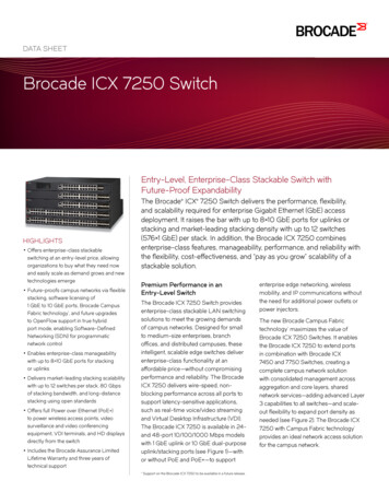
Chapter1Product OverviewIn this chapter Hardware features. . . . . . . . . . . . . . . . . . . . . . . . . . . . . . . . . . . . . . . . . . . . . . . Network and management interfaces . . . . . . . . . . . . . . . . . . . . . . . . . . . . . . . Port, system, and power status LEDs. . . . . . . . . . . . . . . . . . . . . . . . . . . . . . . . Power supplies. . . . . . . . . . . . . . . . . . . . . . . . . . . . . . . . . . . . . . . . . . . . . . . . . .1249Hardware featuresThe following sections describe the physical characteristics of an ICX 6430-C device. For moredetails about physical dimensions and power supply specifications, refer to Chapter 5, “HardwareSpecifications”.ICX 6430-C modelsThere is one ICX 6430-C model: ICX 6430-C12: 12 x 1G Compact Switch (4 PoE/PoE capable ports), 4 x 100/1G Uplinks RJ45& SFP, FanlessFigure 1 and Figure 2 show the front and rear panels of the ICX 6430-C models.FIGURE 1ICX 6430-C12 front panelBrocade ICX 6430-C Compact Switch Hardware Installation Guide53-1002817-021
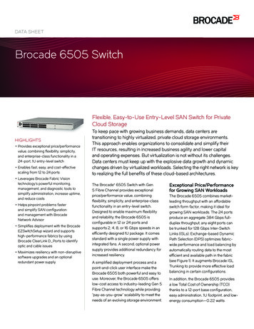
1Network and management interfacesFIGURE 2ICX 6430-C12 rear panelNetwork and management interfacesThe ICX 6430-C12 device includes the following management interfaces, and a reset button on thefront panel of the device: Console management interface (RJ45 serial port) Out-of-band management interface (RJ45 port) Reset buttonThese RJ45 management ports are located together on the left side of the front panel. Refer toFigure 3.FIGURE 3Management interfaces on an ICX 6430-C12 device1Console port3Slot 2 (Copper uplink ports)5Out-of-bandmanagement port2Slot 1 (10/100/1000 Mbps ports)4Slot 3 (SFP uplink ports)6Reset buttonConsole management interfaceThe console management interface is an RJ45 serial port that allows you to configure and managethe device using a third-party terminal emulation application from a directly connected PC.Out-of-band management interfaceThe out-of-band management interface is an RJ45 port that allows you to configure and managethe device from the network.2Brocade ICX 6430-C Compact Switch Hardware Installation Guide53-1002817-02
Network and management interfaces1Reset buttonThe reset button allows you to restart the system without switching the power supplies off and onor using the CLI or Web Management Interface. When reset button is pressed, the system resetsand the software is reloaded. The button is directly below the power LED on the very left of thedevice’s front panel.Network interfaces for a ICX 6430-C deviceAn ICX 6430-C12 device contains the following interfaces: 12 1GbE ports with RJ45 copper connectors (Slot 1, Ports 1- 12)- Ports 1- 4 are dedicated PoE/PoE ports.Standard 802.3at PoE ports support up to 30W per port.Standard 802.3af PoE ports support up to 15.4W per port.Total PoE power capacity is 68W.Some possible PoE/PoE configuration combinations include: 2 standard PoE ports supporting full capacity (15.4W x 2 30.8W)1 standard PoE port supporting full capacity (30W)1 PoE or PoE port supporting partial capacity, no greater than 7W (7W)Total PoE/PoE power: 67.8W 2 standard PoE ports supporting full capacity (30W x 2 60W)1 PoE or PoE port supporting partial capacity, no greater than 7W (7W)Total PoE/PoE power: 67W 4 standard PoE ports supporting full capacity (15.4W x 4 62W)Total PoE power: 62W 4 100/1GbE uplink ports:- 2 100/1GbE RJ45 uplink ports (Slot 2, ports C1-C2)- 2 100/1GbE SFP uplink ports (Slot 3, ports F1-F2)Slot designationsTable 1 lists the slot designations for an ICX 6430-C device. Refer to Figure 3 for the location ofslots 1- 3 on the front panel of an ICX 6430-C device.TABLE 1Slot designations for a ICX 6430-C deviceDeviceSlot 1 (1GbE RJ45 ports)Slot 2 (100/1GbE RJ45 ports)Slot 3 (100/1GbE SFP ports)ICX 6430-C121GbE ports 1-12100/1GbE ports C1- C2100/1GbE SFP ports F1-F2Brocade ICX 6430-C Compact Switch Hardware Installation Guide53-1002817-023
1Port, system, and power status LEDs1GbE RJ45 portsAn ICX t6430-C device provides 12 RJ45 ports that reside on Slot 1 of the device. The 12 RJ45ports operate at 10 Mbps or 100 Mbps half or full duplex, or at 1000 Mbps full duplex. Because allports support automatic MDI or MDI-X operation, you can use straight-through cables for allnetwork connections to PCs or servers, or to other devices or hubs. In addition, it is ideal (andpreferred) to use straight-through cables for switch-to-switch connections.Each port supports auto-negotiation, so the optimum transmission mode (half or full duplex), andthe data rate (10, 100, or 1000 Mbps) can be selected automatically. If a device connected to oneof these ports does not support auto-negotiation, the communication mode of the port can beconfigured manually.100/1GbE uplink portsAn ICX 6430-C device provides 4 independent 100Mbps/1GbE uplink ports.100/1GbE RJ45 ports C1 and C2, residing on slot 2 of the device, can be used as uplink ports oradditional network connections.Additionally, an ICX 6430-C device contains two 100Mbps/1GbE small form factor pluggable (SFP)ports (ports F1 and F2). These ports reside on slot 3 of the switch and can be used as uplink ports.In future releases they can be used for stacking, though the stacking functionality is not availablein release 08.0.00. The SFP ports support 100Mbps/1GbE port speeds.For information about supported SFP transceivers, refer to the following Brocade /data sheets/product data sheets/OpticsDS.pdfPort, system, and power status LEDsAn ICX 6430-C device include LEDs that indicate the status of device components: “Port status LEDs” “System status LEDs” (including power status LEDs) “Network connection status LEDs”Port status LEDsFigure 4 shows the location of the port status LEDs on the ICX 6430-C12 model.4Brocade ICX 6430-C Compact Switch Hardware Installation Guide53-1002817-02
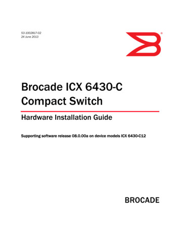
Port, system, and power status LEDsFIGURE 41Port status LEDs an ICX 6430-C12 device1Port status LEDs2PoE/PoE LEDsTable 2 lists the port status LEDs on an ICX 6430-C device and their corresponding conditions andstatus.TABLE 2Port status LEDsLEDConditionStatusOut-of-bandmanagementport (2 LEDs)Off (right side)OfflineOn/Flashing (left side)Link-up. Flashing indicates the port is transmitting and receivinguser packets.On/Green (right side)1 Gbps Link-upRight LED off, left LEDon or flashing10/100 Mbps Link-up. Flashing indicates the port is transmittingand receiving user packets.Off (right side)The right LED on the ports indicates PoE/PoE activity and is onlyactive on ports 1-4. On non-PoE/PoE ports, the right LEDremains off.Off (left side)A link is not established with a remote port.On/Flashing Green(left side)The port has established a valid link at 10, 100 or 1000 Mbps.Flashing indicates the port is transmitting and receiving userpackets.PoE/PoE (1 - 4)On/Green (right side)The port is providing PoE or PoE power to a connected device.Off (right side)The port is not providing PoE or PoE power.100/1GbE RJ45ports(C1 - C2, Slot 2)Link/ActOn/ Flashing GreenThe port is operating at 1 Gbps. Flashing indicates the port istransmitting and receiving user packets at 1 Gbps.OffA link is not established with a remote port.100/1GbE SFPports(F1 - F2, Slot 3)Link/ActOn/ Flashing GreenThe SFP port is operating at 1 Gbps. Flashing indicates the port istransmitting and receiving user packets at 1 Gbps.OffA link is not established with a remote port.1GbE ports(1 - 12, Slot 1)Link/ActSystem status LEDsFigure 5 shows the location of the system status LEDs on an ICX 6430-C device.Brocade ICX 6430-C Compact Switch Hardware Installation Guide53-1002817-025
1Port, system, and power status LEDsFIGURE 51System status LEDs on an ICX 6430-C12 deviceSystem status LEDsTable 3 lists the system status LEDs on an ICX 6430-C device and their corresponding conditionsand status.TABLE 3System status LEDsLEDConditionStatusPWR(Power)GreenPower supply is operating normally.AmberPower supply fault.OffPower supply off.Flashing GreenSystem self-diagnostic test in progress. System reloads automatically.Steady AmberSystem self-diagnostic test has detected a fault. (Fan, thermal, or anyinterface fault.) The user must reload the system.Steady GreenSystem self-diagnostic test passed.Uplink(Reserved for futureuse)OffLED is reserved for future use.Downlink(Reserved for futureuse)OffLED is reserved for future use.ID (1-4)(Reserved for futureuse)OffLED is reserved for future use.Diag(Diagnostic)Network connection status LEDsAfter you install the network cables, you can observe certain LEDs to determine if the networkconnections are functioning properly. Table 4 outlines the LEDs related to the network connections,the desired state of each LED, possible abnormal states of each LED, and what to do if an LEDindicates an abnormal state.6Brocade ICX 6430-C Compact Switch Hardware Installation Guide53-1002817-02
Port, system, and power status LEDsTABLE 41Network connection-related LED statesLEDDesiredstateMeaningAbnormal stateMeaning or actionEthernet(1-12, Slot 1)Link/ActOn orflashing(Green)The port has establisheda valid link at 10, 100 or1000 Mbps. Flashingindicates the port istransmitting and receivinguser packets.OffA link is not established with theremote port. You can do the following: Verify that the connection to theother network device has beenproperly made. Also, makecertain that the other networkdevice is powered on andoperating correctly. Verify that the port has not beendisabled through a configurationchange. You can use the CLI. Ifyou have configured an IPaddress on the device, you alsocan use the Web managementinterface or Brocade NetworkAdvisor. If the other actions do notresolve the problem, try using adifferent port or a differentcable.PoE/PoE (1-4, Slot 1)On (Green)The port is providing PoEor PoE power to aconnected device.OffA link is not established with the PoEdevice. You can do the following: Verify that the connection to theother network device has beenproperly made. If the other actions do notresolve the problem, try using adifferent port or a differentcable.Brocade ICX 6430-C Compact Switch Hardware Installation Guide53-1002817-027
1Port, system, and power status LEDsTABLE 4Network connection-related LED states (Continued)LEDDesiredstateMeaningAbnormal stateMeaning or actionSFP(F1 - F2, Slot3)On orflashing(Green)The SFP port is operating.Flashing green indicatesthe port is transmittingand receiving userpackets.OffA link is not established with theremote port. You can do the following: Verify that the connection to theother network device has beenproperly made. Also, makecertain that the other networkdevice is powered on andoperating correctly. Verify that the transmit port onthe device is connected to thereceive port on the othernetwork device, and that thereceive port on the device isconnected to the transmit porton the other network device. Ifyou are not certain, remove thetwo cable connectors from theport connector and reinsertthem in the port connector,reversing their order. Dust may have accumulated inthe cable connector or portconnector. Verify that the port has not beendisabled through a configurationchange. If the other actions do notresolve the problem, try using adifferent port or a differentcable.Uplink ports(C1-C2, Slot2)On orflashing(Green)The ports are operating.Flashing green indicatesthe port is transmittingand recieving userpackets.OffA link is not established with theremote port. You can do the following: Verify that the connection to theother network device has beenproperly made. Also, makecertain that the other networkdevice is powered on andoperating correctly. Verify that the port has not beendisabled through a configurationchange. You can use the CLI. Ifyou have configured an IPaddress on the device, you alsocan use the Web managementinterface or Brocade NetworkAdvisor. If the other actions do notresolve the problem, try using adifferent port or a differentcable.If a problem persists after taking these actions, contact Brocade Technical Support.8Brocade ICX 6430-C Compact Switch Hardware Installation Guide53-1002817-02
Power supplies1Power suppliesAn ICX 6430-C device has one standard power supply receptacle on the rear panel of the device forthe AC power cord (Figure 6).FIGURE 6ICX 6430-C AC power connection1Kensington lock hole2AC power supply socketPower supply usageThe maximum power capacity of the ICX 6430-C12 device is 100W. 23W drawn from the AC linepower supply input (of the total 100W capacity of the device) are necessary to power the ICX6430-C12 device. PoE/PoE power capacity and output capability is 68W.Brocade ICX 6430-C Compact Switch Hardware Installation Guide53-1002817-029
110Power suppliesBrocade ICX 6430-C Compact Switch Hardware Installation Guide53-1002817-02
Chapter2ICX 6430-C InstallationIn this chapter Items included with an ICX 6430-C device . . . . . . . . . . . . . . . . . . . . . . . . . . Summary of installation tasks . . . . . . . . . . . . . . . . . . . . . . . . . . . . . . . . . . . . Installation precautions . . . . . . . . . . . . . . . . . . . . . . . . . . . . . . . . . . . . . . . . . Preparing the installation site. . . . . . . . . . . . . . . . . . . . . . . . . . . . . . . . . . . . . Installing the device . . . . . . . . . . . . . . . . . . . . . . . . . . . . . . . . . . . . . . . . . . . . Powering on the system . . . . . . . . . . . . . . . . . . . . . . . . . . . . . . . . . . . . . . . . .111212141530DANGERThe procedures in this manual are intended for qualified service personnel.DANGERBefore beginning the installation, see the precautions in “Power precautions” on page 13.Items included with an ICX 6430-C deviceAn ICX 6430-C device ships with all of the following items included in your shipping container. Verifythe contents of your shipping container. If any items are missing, contact the place of purchase. ICX 6430-C deviceWall mounting kit containing two wall-mount screws and two plastic anchorsOne AC power cord - US onlyPower cable clipConsole cableFour rubber feetChina ROHS sheetRead Me First documentWall Mount Holes Location template (single sheet)Additional mounting options available for order include the following: A wall mount option is available to order for a secure wall mount, in addition to the basic wallmount. An additional rack-mounting kit is available to order to mount the device in a two-post rac
53-1002817-02 24 June 2013 Brocade ICX 6430-C Compact Switch Hardware Installation Guide Supporting software release 08.0.00a on device models ICX 6430-C12