Transcription
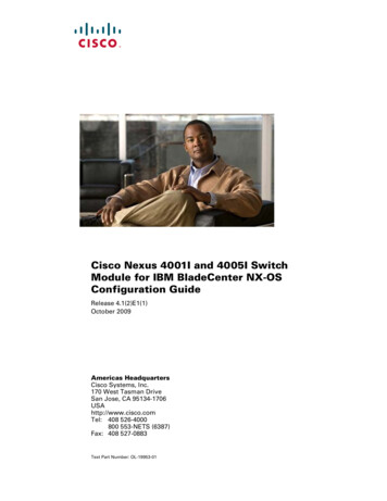
A P P E N D I XBCase Study: Troubleshooting Cisco IP PhoneCallsThis appendix contains two case studies: Troubleshooting Intracluster Cisco IP Phone Calls Troubleshooting Intercluster Cisco IP Phone CallsTroubleshooting Intracluster Cisco IP Phone CallsThe case study in this section discusses in detail the call flow between two Cisco IP Phones within acluster, called an intracluster call. This case study also focuses on Cisco CallManager andCisco IP Phone initialization, registration, and keepalive processes. A detailed explanation of anintracluster call flow follows the discussion. The explanation of the processes are explained using thetrace utilities and tools discussed in Chapter 2, “Troubleshooting Tools.”This section contains the following topics: Sample Topology Cisco IP Phone Initialization Process Cisco CallManager Initialization Process Self-Starting Processes Cisco CallManager Registration Process Cisco CallManager KeepAlive Process Cisco CallManager Intracluster Call Flow TracesSample TopologyGiven that you have two clusters named Cluster 1 and Cluster 2, the two Cisco CallManagers in Cluster1 are called CCM3 and CCM4, while the two Cisco CallManagers in Cluster 2 are called CCM1 andCCM2.The traces collected for this case study come from CCM1, which is located in Cluster 2, as shown inFigure B-1. The basis for the call flow are the two Cisco IP Phones in Cluster 2. The IP addresses ofthese two Cisco IP Phones are 172.16.70.230 (directory number 1000) and 172.16.70.231 (directorynumber 1001), respectively.Troubleshooting Guide for Cisco CallManager Release 5.0(1)OL-8764-01B-1
Appendix BCase Study: Troubleshooting Cisco IP Phone CallsTroubleshooting Intracluster Cisco IP Phone CallsFigure B-1Sample Topology of Intracluster Cisco IP Phone-to-Cisco IP Phone CallsIOS 2.16.70.245IP .229PSTNCluster 1 T1/PRI T1/CAS RASCluster 2Zone 245436Zone 1Cisco IP Phone Initialization ProcessThe following procedure explains in detail the Cisco IP Phone initialization (or boot up) process.ProcedureStep 1If you have set the appropriate options in DHCP server (such as Option 066 or Option 150), theCisco IP Phone sends a request, at initialization to the DHCP server to get an IP address, Domain NameSystem (DNS) server address, and TFTP server name or address. It also gets a default gateway addressif you have set these options in the DHCP server (Option 003).Step 2If a DNS name of the TFTP sever is sent by DHCP, you need a DNS server IP address to map the nameto an IP address. Bypass this step if the DHCP server sends the IP address of the TFTP server. In thiscase study, the DHCP server sent the IP address of TFTP because DNS was not configured.Step 3If a TFTP server name is not included in the DHCP reply, the Cisco IP Phone uses the default servername.Step 4The configuration file (.cnf) file gets retrieved from the TFTP server. All .cnf files have the nameSEP mac address .cnf. If this is the first time the phone is registering with the Cisco CallManager, adefault file, SEPdefault.cnf, gets downloaded to the Cisco IP Phone. In this case study, the firstCisco IP Phone uses the IP address 172.16.70.230 (its MAC address is SEP0010EB001720), and thesecond Cisco IP Phone uses the IP address 172.16.70.231 (its MAC address is SEP003094C26105).Step 5All .cnf files include the IP address(es) for the primary and secondary Cisco CallManager(s). TheCisco IP Phone uses this IP address to contact the primary Cisco CallManager and to register.Step 6Once the Cisco IP Phone connects and registers with Cisco CallManager, the Cisco CallManager tellsthe Cisco IP Phone which executable version (called a load ID) to run. If the specified version does notmatch the executing version on the Cisco IP Phone, the Cisco IP Phone will request the new executablefrom the TFTP server and reset automaticallyTroubleshooting Guide for Cisco CallManager Release 5.0(1)B-2OL-8764-01
Appendix BCase Study: Troubleshooting Cisco IP Phone CallsTroubleshooting Intracluster Cisco IP Phone CallsCisco CallManager Initialization ProcessThis section explains the initialization process of Cisco CallManager with the help of traces that arecaptured from CCM1 (identified by the IP address 172.16.70.228). As described previously, SDI tracesprovide a very effective troubleshooting tool because they detail every packet sent between endpoints.This section describes the events that occur when Cisco CallManager is initialized. Understanding howto read traces will help you to properly troubleshoot the various Cisco CallManager processes and theeffect of those processes on services such as conferencing and call forwarding.The following messages from the Cisco CallManager SDI trace utility show the initialization process onone of the Cisco CallManagers, in this case, CCM1. The first message indicates that Cisco CallManager started its initialization process. The second message indicates that Cisco CallManager read the default database values (for thiscase, it is the primary or publisher database). The third message indicates Cisco CallManager received the various messages on TCP port 8002. The fourth message shows that, after receiving to these messages, Cisco CallManager added asecond Cisco CallManager to its list: CCM2 (172.16.70.229). The fifth message indicates that Cisco CallManager has started and is running Cisco CallManagerversion 3.1(1).16:02:47.765 CCM CMProcMon - CallManagerState Changed - Initialization Started.16:02:47.796 CCM NodeId: 0, EventId: 107 EventClass: 3 EventInfo: Cisco CM DatabaseDefaults Read16:02:49.937 CCM SDL Info - NodeId: [1], Listen IP/Hostname: [172.16.70.228], ListenPort: [8002]16:02:49.984 CCM dBProcs - Adding SdlLink to NodeId: [2], IP/Hostname: [172.16.70.229]16:02:51.031 CCM NodeId: 1, EventId: 1 EventClass: 3 EventInfo: Cisco CallManagerVersion 3.1(1) startedSelf-Starting ProcessesOnce Cisco CallManager is up and running, it starts several other processes within itself. Some of theseprocesses follow, including MulticastPoint Manager, UnicastBridge Manager, digit analysis, and routelist. You will find the messages described during these processes very useful when you aretroubleshooting a problem related to the features in Cisco CallManager.For example, assume that the route lists are not functioning and are unusable. To troubleshoot thisproblem, you would monitor these traces to determine whether the Cisco CallManager has startedRoutePlanManager and if it is trying to load the RouteLists. The sample configuration below shows thatRouteListName ''ipwan'' and RouteGroupName ''ipwan'' are loading and 16:02:51.671CCM MulicastPointManager - StartedCCM UnicastBridgeManager - StartedCCM MediaTerminationPointManager - StartedCCM MediaCoordinator(1) - startedCCM NodeId:1, EventId: 1543 EventClass:2 EventInfo: Database managerCCM NodeId:1, EventId: 1542 EventClass:2 EventInfo: Link managerCCM NodeId:1, EventId: 1541 EventClass:2 EventInfo: Digit analysisCCM RoutePlanManagerCCM RoutePlanManagerCCM RoutePlanManagerCCM RoutePlanManager-Started, loading RouteListsfinished loading RouteListsfinished loading RouteGroupsDisplaying Resulting RoutePlanTroubleshooting Guide for Cisco CallManager Release 5.0(1)OL-8764-01B-3
Appendix BCase Study: Troubleshooting Cisco IP Phone CallsTroubleshooting Intracluster Cisco IP Phone 2:51.671Order16:02:51.671CCM RoutePlanServer - RouteList Info, by RouteList and RouteGroup SelectionCCM RouteList - RouteListName ''ipwan''CCM RouteList - RouteGroupName ''ipwan''CCM RoutePlanServer - RouteGroup Info, by RouteGroup and Device SelectionCCM RouteGroup - RouteGroupName ''ipwan''The following trace shows the RouteGroup adding the device 172.16.70.245, which is CCM3 located inCluster 1 and is considered an H.323 device. In this case, the RouteGroup is created to route calls toCCM3 in Cluster 1 with Cisco IOS Gatekeeper permission. If a problem occurs while routing the call toa Cisco IP Phone located in Cluster 1, the following messages would help you find the cause of theproblem.16:02:51.671 CCM RouteGroup - DeviceName ''172.16.70.245''16:02:51.671 CCM RouteGroup -AllPortsPart of the initialization process shows that Cisco CallManager is adding "Dns" (Directory Numbers).By reviewing these messages, you can determine whether the Cisco CallManager has read the directorynumber from the database.16:02:51.671 CCM NodeId:1, EventId: 1540 EventClass: 2 EventInfo: Call controlstarted16:02:51.843 CCM ProcessDb Dn 2XXX,Line 0,Display ,RouteThisPattern, NetworkLocation OffNet, DigitDiscardingInstruction 1, WhereClause 16:02:51.859 CCM Digit analysis: Add local pattern 2XXX , PID: 1,80,116:02:51.859 CCM ForwardManager - Started16:02:51.984 CCM CallParkManager - Started16:02:52.046 CCM ConferenceManager - StartedIn the following traces, the Device Manager in Cisco CallManager statically initializes two devices. Thedevice with IP address 172.17.70.226 represents a gatekeeper, and the device with IP address172.17.70.245 gets another Cisco CallManager in a different cluster. That Cisco CallManager getsregistered as an H.323 Gateway with this Cisco CallManager.16:02:52.250 CCM DeviceManager: Statically Initializing Device;16:02:52.250 CCM DeviceManager: Statically Initializing Device;DeviceName 172.16.70.226DeviceName 172.16.70.245Cisco CallManager Registration ProcessAnother important part of the SDI trace involves the registration process. When a device is powered up,it gets information via DHCP, connects to the TFTP server for its .cnf file, and then connects to theCisco CallManager that is specified in the .cnf file. The device could be an MGCP gateway, a Skinnygateway, or a Cisco IP Phone. Therefore, you need to be able to discover whether devices havesuccessfully registered on the Cisco network.In the following trace, Cisco CallManager has received new connections for registration. The registeringdevices are MTP nsa-cm1 (MTP services on CCM1), and CFB nsa-cm1 (Conference Bridge service onCCM1). Although these are software services that are running on Cisco CallManager, they get treatedinternally as different external services and therefore get assigned a TCPHandle, socket number, and portnumber as well as a device name.16:02:52.750 CCM StationInit - New connection accepted. DeviceName , TCPHandle 0x4fbaa00,Socket 0x594, IPAddr 172.16.70.228, Port 3279, StationD [0,0,0]16:02:52.750 CCM StationInit - New connection accepted. DeviceName , TCPHandle 0x4fe05e8,Socket 0x59c, IPAddr 172.16.70.228, Port 3280, StationD [0,0,0]16:02:52.781 CCM StationInit - Processing StationReg. regCount: 1 DeviceName MTP nsa-cm1,TCPHandle 0x4fbaa00, Socket 0x594, IPAddr 172.16.70.228, Port 3279, StationD [1,45,2]16:02:52.781 CCM StationInit - Processing StationReg. regCount: 1 DeviceName CFB nsa-cm1,TCPHandle 0x4fe05e8, Socket 0x59c, IPAddr 172.16.70.228, Port 3280, StationD [1,96,2]Troubleshooting Guide for Cisco CallManager Release 5.0(1)B-4OL-8764-01
Appendix BCase Study: Troubleshooting Cisco IP Phone CallsTroubleshooting Intracluster Cisco IP Phone CallsCisco CallManager KeepAlive ProcessThe station, device, or service and the Cisco CallManager use the following messages to maintain aknowledge of the communications channel between them. The messages begin the KeepAlive sequencethat ensures that the communications link between the Cisco CallManager and the station remains active.The following messages can originate from either the Cisco CallManager or the station.16:03:02.328 CCM StationInit - InboundStim - KeepAliveMessage - Forward KeepAlive toStationD. DeviceName MTP nsa-cm2, TCPHandle 0x4fa7dc0, Socket 0x568, IPAddr 172.16.70.229,Port 1556, StationD [1,45,1]16:03:02.328 CCM StationInit - InboundStim - KeepAliveMessage - Forward KeepAlive toStationD. DeviceName CFB nsa-cm2, TCPHandle 0x4bf8a70, Socket 0x57c, IPAddr 172.16.70.229,Port 1557, StationD [1,96,1]16:03:06.640 CCM StationInit - InboundStim - KeepAliveMessage - Forward KeepAlive toStationD. DeviceName SEP0010EB001720, TCPHandle 0x4fbb150, Socket 0x600,IPAddr 172.16.70.230, Port 49211, StationD [1,85,2]16:03:06.703 CCM StationInit - InboundStim - KeepAliveMessage - Forward KeepAlive toStationD. DeviceName SEP003094C26105, TCPHandle 0x4fbbc30, Socket 0x5a4,IPAddr 172.16.70.231, Port 52095, StationD [1,85,1]The messages in the following trace depict the KeepAlive sequence that indicates that thecommunications link between the Cisco CallManager and the station is active. Again, these messagescan originate from either the Cisco CallManager or the station.16:03:02.328 CCM MediaTerminationPointControl - stationOutputKeepAliveAcktcpHandle 4fa7dc016:03:02.328 CCM UnicastBridgeControl - stationOutputKeepAliveAck tcpHandle 4bf8a7016:03:06.703 CCM StationInit - InboundStim - IpPortMessageID: 32715(0x7fcb)tcpHandle 0x4fbbc3016:03:06.703 CCM StationD - stationOutputKeepAliveAck tcpHandle 0x4fbbc30Cisco CallManager Intracluster Call Flow TracesThe following SDI traces explore the intracluster call flow in detail. You can identify Cisco IP Phonesin the call flow by the directory number (dn), tcpHandle, and IP address. A Cisco IP Phone (dn: 1001,tcpHandle: 0x4fbbc30, IP address: 172.16.70.231) located in Cluster 2 is calling another Cisco IP Phonein the same Cluster (dn 1000, tcpHandle 0x4fbb150, IP address 172.16.70.230). Remember that youcan follow a device through the trace by looking at the TCP handle value, time stamp, or name of thedevice. The TCP handle value for the device remains the same until the device is rebooted or goes offline.The following traces show that the Cisco IP Phone (1001) has gone off hook. The trace below shows theunique messages, TCP handle, and the called number, which display on the Cisco IP Phone. No callingnumber appears at this point because the user has not tried to dial any digits. The information belowappears in the form of Skinny Station messages between the Cisco IP Phones and theCisco CallManager.16:05:41.625 CCM StationInit - InboundStim - OffHookMessageID tcpHandle 0x4fbbc3016:05:41.625 CCM StationD - stationOutputDisplayText tcpHandle 0x4fbbc30, Display 1001The next trace shows Skinny Station messages going from Cisco CallManager to a Cisco IP Phone. Thefirst message is to turn on the lamp on the calling party Cisco IP Phone.16:05:41.625 CCM StationD - stationOutputSetLamp stim: 9 Line instance 1 lampMode LampOntcpHandle 0x4fbbc30Cisco CallManager uses the stationOutputCallState message to notify the station of certain call-relatedinformation.16:05:41.625 CCM StationD - stationOutputCallState tcpHandle 0x4fbbc30Troubleshooting Guide for Cisco CallManager Release 5.0(1)OL-8764-01B-5
Appendix BCase Study: Troubleshooting Cisco IP Phone CallsTroubleshooting Intracluster Cisco IP Phone CallsCisco CallManager uses the stationOutputDisplayPromptStatus message to cause a call-related promptmessage to display on the Cisco IP Phone.16:05:41.625 CCM StationD - stationOutputDisplayPromptStatus tcpHandle 0x4fbbc30Cisco CallManager uses the stationOutputSelectSoftKey message to cause the Skinny Station to choosea specific set of soft keys.16:05:41.625 CCM StationD - stationOutputSelectSoftKeys tcpHandle 0x4fbbc30Cisco CallManager uses the next message to instruct the Skinny Station as to the correct line context forthe display.16:05:41.625 CCM StationD - stationOutputActivateCallPlane tcpHandle 0x4fbbc30In the following message, the digit analysis process is ready to identify incoming digits and check themfor potential routing matches in the database. The entry, cn 1001, represents the calling party numberwhere dd "" represents the dialed digit, which would show the called party number. The phone sendsStationInit messages, Cisco CallManager sends StationD messages, and Cisco CallManager performsdigit analysis.16:05:41.625 CCM Digit analysis: match(fqcn "", cn "1001", pss "", dd "")16:05:41.625 CCM Digit analysis: potentialMatches PotentialMatchesExistThe following debug message shows that the Cisco CallManager is providing inside dial tone to thecalling party Cisco IP Phone.16:05:41.625 CCM StationD - stationOutputStartTone: 33 InsideDialTone tcpHandle 0x4fbbc30After Cisco CallManager detects an incoming message and recognizes that the keypad button 1 has beenpressed on the Cisco IP Phone, it immediately stops the output tone.16:05:42.890 CCM StationInit - InboundStim - KeypadButtonMessageID kpButton: 1tcpHandle 0x4fbbc3016:05:42.890 CCM StationD - stationOutputStopTone tcpHandle 0x4fbbc3016:05:42.890 CCM StationD - stationOutputSelectSoftKeys tcpHandle 0x4fbbc3016:05:42.890 CCM Digit analysis: match(fqcn "", cn "1001", pss "", dd "1")16:05:42.890 CCM Digit analysis: potentialMatches PotentialMatchesExist16:05:43.203 CCM StationInit - InboundStim - KeypadButtonMessageID kpButton: 0tcpHandle 0x4fbbc3016:05:43.203 CCM Digit analysis: match(fqcn "", cn "1001", pss "", dd "10")16:05:43.203 CCM Digit analysis: potentialMatches PotentialMatchesExist16:05:43.406 CCM StationInit - InboundStim - KeypadButtonMessageID kpButton: 0tcpHandle 0x4fbbc3016:05:43.406 CCM Digit analysis: match(fqcn "", cn "1001", pss "", dd "100")16:05:43.406 CCM Digit analysis: potentialMatches PotentialMatchesExist16:05:43.562 CCM StationInit - InboundStim - KeypadButtonMessageID kpButton: 0tcpHandle 0x4fbbc3016:05:43.562 CCM Digit analysis: match(fqcn "", cn "1001", pss "", dd "1000")After the Cisco CallManager has received enough digits to match, it provides the digit analysis resultsin a table format. Cisco CallManager ignores any extra digits that are pressed on the phone after thispoint because a match has already been found.16:05:43.562 CCM Digit analysis: analysis results16:05:43.562 CCM PretransformCallingPartyNumber 1001 CallingPartyNumber 1001 DialingPattern 1000 DialingRoutePatternRegularExpression (1000) PotentialMatches PotentialMatchesExist DialingSdlProcessId (1,38,2) PretransformDigitString 1000 PretransformPositionalMatchList 1000 CollectedDigits 1000Troubleshooting Guide for Cisco CallManager Release 5.0(1)B-6OL-8764-01
Appendix BCase Study: Troubleshooting Cisco IP Phone CallsTroubleshooting Intracluster Cisco IP Phone Calls PositionalMatchList 1000 RouteBlockFlag RouteThisPatternThe next trace shows that Cisco CallManager is sending out this information to a called party phone (thetcpHandle number identifies the phone).16:05:43.578 CCM StationD - stationOutputCallInfo CallingPartyName 1001,CallingParty 1001, CalledPartyName 1000, CalledParty 1000, tcpHandle 0x4fbb150The next trace indicates that Cisco CallManager is ordering the lamp to blink for incoming callindication on the called party Cisco IP Phone.16:05:43.578 CCM StationD - stationOutputSetLamp stim: 9 Line instance 1lampMode LampBlink tcpHandle 0x4fbb150In the following traces, Cisco CallManager provides ringer, display notification, and other call-relatedinformation to the called party Cisco IP Phone. Again, you can see that all messages get directed to thesame Cisco IP Phone because the same tcpHandle gets used throughout the 3.578CCM StationDCCM StationDCCM StationDCCM StationD-stationOutputSetRinger: 2 InsideRing tcpHandle 0x4fbb150stationOutputDisplayNotify tcpHandle 0x4fbb150stationOutputDisplayPromptStatus tcpHandle 0x4fbb150stationOutputSelectSoftKeys tcpHandle 0x4fbb150Notice that Cisco CallManager also provides similar information to the calling party Cisco IP Phone.Again, the tcpHandle differentiates between Cisco IP Phones.16:05:43.578 CCM StationD - stationOutputCallInfo CallingPartyName 1001,CallingParty 1001, CalledPartyName , CalledParty 1000, tcpHandle 0x4fbbc3016:05:43.578 CCM StationD - stationOutputCallInfo CallingPartyName 1001,CallingParty 1001, CalledPartyName 1000, CalledParty 1000, tcpHandle 0x4fbbc30In the next trace, Cisco CallManager provides an alerting or ringing tone to the calling partyCisco IP Phone, notifying that the connection has been :05:43.578CCM StationDCCM StationDCCM StationDCCM StationD-stationOutputStartTone: 36 AlertingTone tcpHandle 0x4fbbc30stationOutputCallState tcpHandle 0x4fbbc30stationOutputSelectSoftKeys tcpHandle 0x4fbbc30stationOutputDisplayPromptStatus tcpHandle 0x4fbbc30At this point, the called party’s Cisco IP Phone goes off hook; therefore, Cisco CallManager stopsgenerating the ringer tone to calling party.16:05:45.140 CCM StationD - stationOutputStopTone tcpHandle 0x4fbbc30In the following messages, Cisco CallManager causes the Skinny Station to begin receiving a UnicastRTP stream. To do so, Cisco CallManager provides the IP address of the called party as well as codecinformation and packet size in msec (milliseconds). PacketSize designates an integer that contains thesampling time, in milliseconds, that is used to create the RTP packets.NoteNormally this value gets set to 30 msec. In this case, it is set to 20 msec.16:05:45.140 CCM StationD - stationOutputOpenReceiveChannel tcpHandle 0x4fbbc30 myIP:e74610ac (172.16.70.231)16:05:45.140 CCM StationD - ConferenceID: 0 msecPacketSize: 20compressionType:(4)Media Payload G711Ulaw64kSimilarly, Cisco CallManager provides information to the called party (1000).16:05:45.140 CCM StationD - stationOutputOpenReceiveChannel tcpHandle 0x4fbb150 myIP:e64610ac (172.16.70.230)16:05:45.140 CCM StationD - ConferenceID: 0 msecPacketSize: 20compressionType:(4)Media Payload G711Ulaw64kTroubleshooting Guide for Cisco CallManager Release 5.0(1)OL-8764-01B-7
Appendix BCase Study: Troubleshooting Cisco IP Phone CallsTroubleshooting Intercluster Cisco IP Phone CallsCisco CallManager has received the acknowledgment message from called party for establishing theopen channel for RTP stream, as well as the IP address of the called party. This message informs theCisco CallManager of two pieces of information about the Skinny Station. First, it contains the status ofthe open action. Second, it contains the receive port address and number for transmission to the remoteend. The IP address of the transmitter (calling part) of the RTP stream is ipAddr, and PortNumber is theIP port number of the RTP stream transmitter (calling party).16:05:45.265 CCM StationInit - InboundStim - StationOpenReceiveChannelAckIDtcpHandle 0x4fbb150, Status 0, IpAddr 0xe64610ac, Port 17054, PartyID 2Cisco CallManager uses the following messages to order the station to begin transmitting the audio andvideo streams to the indicated remote Cisco IP Phone IP address and port number.16:05:45.265 CCM StationD - stationOutputStartMediaTransmission tcpHandle 0x4fbbc30 myIP:e74610ac (172.16.70.231)16:05:45.265 CCM StationD - RemoteIpAddr: e64610ac (172.16.70.230) RemoteRtpPortNumber:17054 msecPacketSize: 20 compressionType:(4)Media Payload G711Ulaw64k16:03:25.328 CCM StationD(1):TCPPid [1.100.117.1] OpenMultiReceiveChannelconferenceID 16777217 passThruPartyID 1000011 compressionType 101(Media Payload H263)qualifierIn ?.myIP: e98e6b80 (128.107.142.233) CT::1,100,11,1.1 IP:: DEV:: 16:03:25.375 CCM StationInit: TCPPid [1.100.117.1] StationOpenMultiMediaReceiveChannelAckStatus 0, IpAddr 0xe98e6b80, Port 65346,PartyID 16777233 CT::1,100,105,1.215 IP::128.107.142.233 16:03:25.375 CCM StationD(2):TCPPid [1.100.117.2]star StationOutputStartMultiMediaTransmission conferenceID 16777218passThruPartyID 16777250 remoteIpAddress e98e6b80(66.255.0.0)remotePortNumber 65346compressType 101(Media Payload H263) qualifierOut ?. myIP: e98e6b80(128.107.142.233) CT::1,100,105,1.215 IP::128.107.142.233 In the following traces, the previously explained messages are sent to the called party. The messages thatindicate that the RTP media stream has been started between the called and calling party, follow thesemessages.16:05:45.312 CCM StationD - stationOutputStartMediaTransmission tcpHandle 0x4fbb150 myIP:e64610ac (172.16.70.230)16:05:45.328 CCM StationD - RemoteIpAddr: e74610ac (172.16.70.231) RemoteRtpPortNumber:18448 msecPacketSize: 20 compressionType:(4)Media Payload G711Ulaw64k16:05:46.203 CCM StationInit - InboundStim - OnHookMessageID tcpHandle 0x4fbbc30The calling party Cisco IP Phone finally goes on hook, which terminates all the control messagesbetween the Skinny Station and Cisco CallManager as well as the RTP stream between Skinny Stations.16:05:46.203 CCM StationInit - InboundStim - OnHookMessageID tcpHandle 0x4fbbc30Troubleshooting Intercluster Cisco IP Phone CallsThe case study in this section examines a Cisco IP Phone that is calling another Cisco IP Phone that islocated in a different cluster. This type of call is also known as an intercluster Cisco IP Phone call.This section contains the following topics: Sample Topology Intercluster H.323 Communication Call Flow Traces Failed Call FlowTroubleshooting Guide for Cisco CallManager Release 5.0(1)B-8OL-8764-01
Appendix BCase Study: Troubleshooting Cisco IP Phone CallsTroubleshooting Intercluster Cisco IP Phone CallsSample TopologyThe following sample topology gets used in this case study. Two clusters, each having twoCisco CallManagers, and also Cisco IOS Gateways and a Cisco IOS Gatekeeper are in place.Intercluster H.323 CommunicationThe Cisco IP Phone in Cluster 1 makes a call to the Cisco IP Phone in Cluster 2. InterclusterCisco CallManager communication takes place using the H.323 Version 2 protocol. ACisco IOS Gatekeeper also serves for admission control.The Cisco IP Phone can connect to the Cisco CallManager via Skinny Station protocol, and theCisco CallManager can connect with the Cisco IOS Gatekeeper by using the H.323 Registration,Admission, and Status (RAS) protocol. The admission request message (ARQ) gets sent to theCisco IOS Gatekeeper, which sends the admission confirmed message (ACF) after making sure theintercluster call can be made using H.323 version 2 protocol. Once this happens, the audio path getsmade by using the RTP protocol between Cisco IP Phones in different clusters.Call Flow TracesThis section discusses the call flow by using SDI trace examples captured in the CCM000000000 file.The traces discussed in this case study focus only on the call flow itself.In this call flow, a Cisco IP Phone (2002) located in Cluster 2 is calling a Cisco IP Phone (1001) locatedin Cluster 1. Remember that you can follow a device through the trace by looking at the TCP handlevalue, time stamp, or name of the device. The TCP handle value for the device remains the same untilthe device is rebooted or goes offline.In the following traces, the Cisco IP Phone (2002) has gone off hook. The trace shows the uniquemessages, TCP handle, and the calling number, which displays on the Cisco IP Phone. The followingdebug output shows the called number (1001), H.225 connect, and H.245 confirm messages. The codectype is G.711 mu-law.16:06:13.921 CCM StationInit - InboundStim - OffHookMessageID tcpHandle 0x1c6431016:06:13.953 CCM Out Message -- H225ConnectMsg -- Protocol H225Protocol16:06:13.953 CCM Ie - H225UserUserIe IEData 7E 00 37 05 02 C0 0616:06:13.953 CCM StationD - stationOutputCallInfo CallingPartyName , CallingParty 2002,CalledPartyName 1001, CalledParty 1001, tcpHandle 0x1c6431016:06:14.015 CCM H245Interface(2) OLC indication chan number 216:06:14.015 CCM StationD - stationOutputOpenReceiveChannel tcpHandle 0x1c64310 myIP:e74610ac (172.16.70.231)16:06:14.015 CCM StationD - ConferenceID: 0 msecPacketSize: 20compressionType:(4)Media Payload G711Ulaw64k16:06:14.062 CCM StationInit - InboundStim - StationOpenReceiveChannelAckIDtcpHandle 0x1c64310, Status 0, IpAddr 0xe74610ac, Port 20444, PartyID 216:06:14.062 CCM H245Interface(2) paths established ip e74610ac, port 2044416:06:14.187 CCM H245Interface(2) OLC outgoing confirm ip fc4610ac, port 29626The following traces show the calling and called party number, which associates with an IP address anda hexidecimal value.16:06:14.187 CCM StationD - stationOutputStartMediaTransmission tcpHandle 0x1c64310 myIP:e74610ac (172.16.70.231)16:06:14.187 CCM StationD - RemoteIpAddr: fc4610ac (172.16.70.252)Troubleshooting Guide for Cisco CallManager Release 5.0(1)OL-8764-01B-9
Appendix BCase Study: Troubleshooting Cisco IP Phone CallsTroubleshooting Intercluster Cisco IP Phone CallsThe following traces show the packet sizes and the MAC address of the Cisco IP Phone (2002). Thedisconnect, then on-hook messages, follow these traces.RemoteRtpPortNumber: 29626 msecPacketSize: 20 compressionType:(4)Media Payload G711Ulaw64k16:06:16.515 CCM Device SEP003094C26105 , UnRegisters with SDL Link to monitor NodeID 116:06:16.515 CCM StationD - stationOutputCloseReceiveChannel tcpHandle 0x1c64310 myIP:e74610ac (172.16.70.231)16:06:16.515 CCM StationD - stationOutputStopMediaTransmission tcpHandle 0x1c64310 myIP:e74610ac (172.16.70.231)16:06:16.531 CCM In Message -- H225ReleaseCompleteMsg -- Protocol H225Protocol16:06:16.531 CCM Ie - Q931CauseIe -- IEData 08 02 80 9016:06:16.531 CCM Ie - H225UserUserIe -- IEData 7E 00 1D 05 05 80 0616:06:16.531 CCM Locations:Orig 1 BW 64Dest 0 BW -1 (-1 implies infinite bw available)16:06:16.531 CCM MediaManager - wait AuDisconnectRequest - StopSession sending disconnectto (64,2) and remove connection from list16:06:16.531 CCM MediaManager - wait AuDisconnectReply - received all disconnect replies,forwarding a reply for party1(16777219) and party2(16777220)16:06:16.531 CCM MediaCoordinator - wait AuDisconnectReply - removing MediaManager(2) fromconnection list16:06:16.734 CCM StationInit - InboundStim - OnHookMessageID tcpHandle 0x1c64310Failed Call FlowThe following section describes an unsuccessful intercluster call flow, as seen in the SDI trace. In thefollowing traces, the Cisco IP Phone (1001) goes off hook. A TCP handle gets assigned to theCisc
System (DNS) server address, and TFTP server name or address. It also gets a default gateway address if you have set these options in the DHCP server (Option 003). . Appendix B Case Study: Troubleshooting Cisco IP Phone Calls Troubleshooting Intracluster Cisco IP Phone Calls