Transcription
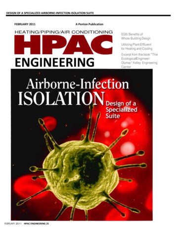
DESIGN OF A SPECIALIZED AIRBORNE-INFECTION-ISOLATION SUITEFEBRUARY 2011A Penton PublicationHEATING/PIPING/AIR CONDITIONINGEGB: Benefits ofWhole-Building DesignUtilizing Plant Effluentfor Heating and CoolingENGINEERINGFEBRUARY 2011HPAC ENGINEERING 25Excerpt from the book "TheEcologicalEngineer:Glumac":Kelley EngineeringCenter
Design of a SpecializedAirborne-InfectionIsolation SuiteLessons learned from the design ofnew National Institutes of Health facilityBy FARHAD MEMARZADEH,PhD, PE,and DEBORAH E.WILSON,DrPH,CBSP,NationalInstitutes of Health,Bethesda,Md.,and KRISHNAN RAMESH,PE,Affiliated Engineers Inc.,Rockville, Md.ria used for the SCSU, wruch can be applied for any othertype of airborne-infection-isolation suite (AilS).General Design FeaturesThe SCSO receives air via the main clinical supply-airsystem, wruch is served by air-handling units located inanother part of the building. Trus is a manifolded systemproviding supply air to all patient rooms and supportspaces (Figure 1).All clinical spaces are served by a non-recirculating(100-percent exhaust) HVAC system. All general clinicalspaces, as weiJ as the adjacent Vaccine Evaluation Clinic(VEC), are served by general exhaust systems consistingof multiple exhaust fans connected to a common exhaustair manifold. Dedicated isolation-room exhaust systemsconsist of multiple exhaust fans connected to a commonexhaust-air manifold. If one fan fails, the remaining fansA biocontainment patient-care unit (BPCU) is a facili ty d igned and operated to maximize patient care withapprcopriate infection-control practices and procedures.A BPCU is secure, is physically separated from otherpatient-care areas, and has special air-handling systems.1Vaccine Evaluation Clinic SpecialCllnlcllStudies UnH (SCSU) (mcludesThe National Institutes of Health'soccupaUonal xposure Isolation room,new Special Clinical Studies Unit (SCSU)patient room, and nursing support)in Bethesda, Md., is a rughly specializedBPCU, housing patients with extremelyinfectious diseases transmissible byrespiratory aerosolization, direct contact with primary body fluids, or driedinfectious particles from body fluids.The SCSU has three patient roomsplus an occupational-exposure isolation room (OETR). It is equipped to meetall clinical-care needs, including basicmedical observation, minor surgicalprocedures, and intensive care. Thus,planning had to address housekeeping, Welded stainless-s18el ductworksecurity, emergency evacuation, andthe use of experimental therapeutics.This article will discuss design criteFIGURE 1 General arrangement of mechanical systemsDirector of the National Institutes of Health's (NIH's) Division of Technical Resources, Farhad Memarzadeh, PhD, PE, consults onmatters related to biocontainment and medical research laboratories around the world. He has written four books and morethan 60 scientific research and technical papers publ.ished in peer-reviewed journals and been a guest and keynote speaker formore than 50 international scientific and engineering conferences and symposia. Deborah E. Wilson, DrPH, CBSP, is director of theNJH's Division of Occupational Health and Safety and founder and director of the National Biosafety and Biocontain- mentTraining Program. She is a career U.S. Public Health Service Commissioned Officer. Krishnan Ramesh, PE, is a managing principalof Affiliated Engineers Inc. He has extensive experience planning, engineering, and designing biological and chemical researchlaboratories and vivaria nationwide and is a technical contributor to the NIH Design Requirements Manual for BiomedicalLaboratories and Animal Research Facilities.FEBRUARY 2011 HPAC ENGINEERING
DESIGN OF A SPECIALIZED AIRBORNE-INFECTION-ISOLATION SUITEcompensate to provide the requireddesign exhaust-air quantity.The VEC is exhausted throughthe general clinical exhaust system,while the SCSU is exhausted througha dedicated system. Exhaust airfrom all SCSU spaces, including theOEIR is manifolded in the dedicatedexhaust system.The dedicated system is equippedwith high-efficiency-particulate-air(HEPA) filters prior to exhaust fansand discharges outside (Figure 2).At both entrances to the SCSU arevestibules maintained at negativepressure relative to the adjoiningcorridors. The OEIR has an anteroom maintained at negative pressure relative to the rest of the SCSUto mitigate the risk of release of anairborne agent. The negative pressure of the patient rooms, the OEIR,and the SCSU is monitored andalarmed at the nurses' station.FEBRUARY 2011HPAC ENGINEERING 25FIGURE 2. Dual-use-isolation-room anteroom mechanical systems.SCSU Design FeaturesDesign features specific to theSCSU include: Walls (outside of the OEIR)sealed to minimize uncontrolledair movement to and from adjacentspaces, sealed piping penetrations,and openings in electrical boxesand other component device boxessealed with caulking.
DESIGN OF A SPECIALIZED AIRBORNE-INFECTION-ISOLATION SUITEFIGURE 3. Dual-use Isolation room. Self-closing exit doors. Balanced ventilation air to main- tainnegative pressure (inflow of air)relative to the corridor (betweenpublic corridor and the SCSU). Exhaust-air grilles located low onpatient-room walJs. Pressure-monitoringsystemcontinuously indicating airflow fromadjacent spaces into the SCSU. Displays of relative space pressurization at the corridor and vestibuJes. Remote alarms at the nurses' station. Twelve-air-changes-per-hour(ACH) minimum ventilation rate ofnon-recirculating air (100- percentoutdoor air) for the SCSU and OEIR. Dedicated toilet, bath, and handwashing facilities in each patientroom. Dedicated exhaust-air systemserving the SCSU and OEIR.The dedicated constant-volumeexhaust system consists of three variable-speed exhaust fans. Each fan isdesigned at 50 percent of capacity toprovide the required level of redundancy and reliability and 20-percentreserve-airflow capacity to accountfor final air-balance adjustments andfuture needs. The fans operate continuously, their speed controlled withvariable-frequency drives based on astatic-pressure sensor in the exhaustductwork. Discharge from the fans ismanifolded to ensure a high stackdischarge velocity.One of t.he exhaust fans receiveslife-safety branch power; t.he othertwo receive general standby-equipment branch power. In the event ofnormal power loss, life-safety power isrestored within 10 sec, and the first fanis re-engaged and ramps up to satisfyrequiredminimum exhaust anddirectionalairflows.Shortlythereafter, power to the other fans isrestored, and the fans are re-engaged. Airdistribution to individual spaces/ roomsis by constant- and/or vari- ablevolume, pressure-independent supplyandexhaust air terminals to eachtemperature- and/or pressure- controlzone. Pairs of supply and ex- haustventuri-style air-term.inal units trackairflowto ensure the specifiedpressurization (directionalairflow) ismaintained. The onJy prerequisite for theair terminals to operate properly issufficient duct static pressure. Th.is ismonitoredviadifferential-pressureswitches across each air valve. Additionally,automatic bubble-tight isolation dampers are provided in thesupply duct to each zone.All exhaust air-terminal units arelow-leakage (less than 3 cfm at 1 in.water), with high-speed actuatorsFEBRUARY 2011 HPAC ENGINEERING
DESIGN OF A SPECIALIZED AIRBORNE-INFECTION-ISOLATION SUITE(less-than-1-sec fuiJ response time)to stay within 5 percent of airflowset point. The air-terminal units'controllers are linked betweensupply and exhaust. If duct stat icpressure falls below levels requiredfor accurate tracking, the supply-airbubble-tight dampers close, and theexhaust-air valves are commandedto a minimum position, maintainingdirectional airflow.The control devices operateautonomously, even in the eventcommunications with the overallbuilding control system are disrupted. All of the controllers andbubble-tight dampers are provideduninterruptible power to ensurethe air-terminal units track each otherto maintain the specified airflowdifferential. AJI serviceable components, such as air terminals, exhaustvalves, and reheat coils, a re locatedin the interstitial space outside of thepatient-care/containment area.All exhaust ductwork for the SCSUand negative-pressure examinationroom on the room side of the HEPAfilter is made of welded stainless steel(Figure 3). The supply ductwork isare sealed airtight to mm1mizeoutside penetrations. A third inner layer of sheetrock prevents airmigration that can occur as theresult of required utility boxes andassociated penetrations.Room Control SequencesUnder normal conditions, supply- and ex haust-air valves oper-FIGURE 4. Manifolded supply-air systems and dedicated exhaust-air system for the SCSUmade of galvanized steel augmentedwith welded stainJess steel. Bubbletight dampers are provided on allsupply ducts branching from theinterstitial level to SCSU patientrooms and the OEIR. These arefast -acting pneumati c actuatorsthat close upon a loss of exhaustairflow. Ductwork from the bubbletight dampers to air devices is madeBacktlow preventers are installedin domestic-water piping running tothe SCSU. When the SCSU is in isolation mode, oxygen, medical vacuum,and medical air are provided via localdedicated units. HEPA filtration isprovided on the main plumbing ventsleaving the SCSU.Em erg ency power i s provid edfor criti cal bra nch, life-safety, a ndstandby equipment in the SCSU andfor exhaust f ans on the interstitiallevel as appropriate.E lectrical services for the OEIRFEBRUARY 2011HPAC ENGINEERING 25.FIGURE 5. ManHolded supply·alr system and dedicated exhaust-air system for the SCSU.
DESIGN OF A SPECIALIZED AIRBORNE-INFECTION-ISOLATION SUITEate at "constant" airflow set points.The fixed differential between supply- and exhaust-airflow set pointsprovides directional airflow androom pressurization. For example,an exhaust-airflow set point of 700cfm and supply-airflow set point of600 cfm provides 100-cfm inwardairflow, maintaining a room atnegative pressure. As long as the"measured" differential pressureacross the supply- and exhaust-airvalves is within an acceptable range(0.6 in. wg to 3.0 in. wg), air valvesmaintain their respective constantairflow set points, maintaining directional airflow and room pressurization. Differential-pressure switchesacross each supply- and exhaust-airvalve continuously monitor airflow.If the differential pressure acrosseither the supply- or exhaust-airvalve in any room drops below 0.3in. wg, the bubble-tight damper onF1GURE 6. Patient-room airflow.the supply duct to that room closesimmediately. The supply-airflow andexhaust-airflow set points are reset toemergency-mode minimum values.When the main supply-duct staticpressure and main exhaust-ductstatic pressure J;se above 0.85 in. wg,the bubble-tight damper opens, sup-,FEBRUARY 2011 HPAC ENGINEERING 29
DESIGN OF A SPECIALIZED AIRBORNE-INFECTION-ISOLATION SUITEply- and exhaust-airflow set pointsare reset to their normal values, andthe room reverts to normal operation. The room control sequences areillustrated in figures 4-6.Particle DynamicsClinically applicable distinctionsare made between short - rangeairborne-infection routes (betweenindividuals less than 3.28 ft apart)and long-range routes (within aroom, between rooms, or betweenindividuals greater than 3.28 ftapart). Small droplets may partici pate in short-range transmission,but are more Jjkely than large droplets to evaporate to become droplet nuclei. True long-range aerosoltransmission becomes possiblewhen droplets of infectious materialare small enough to remam airbornealmost indefinitely and be transmitted over long distances. There isBathroom exhaust (100 cfm)Breathing zone around bedFIGURE7 SCSUventilationsystem.essential agreement tha t particleswith an aerodynamic diameter of5 J.lffi or less are aerosols, while particles with an aerodynantic diameterof 20 pm are large droplets.MethodologyFor the SCSU, computational flillddynamics and particle tracking wereused to study the influence of ventilation flow rate (12 ACH and 16 ACH),exhaust location (high exhaust, lowexhaust, and the combination ofhlghand low exhausts), and patient position (sitting and lying) on the removalof aerosol generated by a cough.The model sillte consisted of threerooms-main isolation room with
DESIGN OF SPECIALIZED AIRBORNE-INFECTION-ISOLATION SUITETABLE 1. Case description aad status of 3,000 particles 3 min and 5 min after a cough.patient bed, bathroom, and anteroom-connected via door gaps.A patient's cough was assumedto release 3,000 droplet nuclei withdiameters of 3 lJm.2*3 Further, theparticles were assumed to be 93 Fwhen released from the mouth.4ResultsThree thousand particles weretracked individually for 5 min, withthe number of particles removedfrom the room recorded every minute. The location of each particleremaining in the room was recorded.Particular attention was pa.id to thenumber of particles remaining inthe breathing zone of the main roomand the breathing zone around thebed where health-care workers weremost likely to be. The breathing zoneof the main room was defined as thespace 3.6 ft to 5.75 ft from the floor;the breathing zone around the bedwas defined as the space 9 in. fromthe edges of, and 3.6 ft to 5.75 ftabove, the bed (Figure 7).Table 1 shows the percentage ofparticles removed from the suite 3min and 5 rrtin after a cough and thepercentages of particles remainingin the bathroom, the main room, andthe breathing zone of the main room.During the first 3 min, the systemremoved 13 percent to 45 percentof the 3,000 particles. Within 5 min,the percentage of particles removedincreased to 25 to 55 percent, whichis consistent with estimates 5 that,assuming a well-mixing condition,99 percent of particles will beremoved after 9 min at 16 ACH.Note the percentage of particles inthe bathroom is much higher whena sitting patient coughs than whena lyjng patient coughs. The reasonis the distribution of particles in theair current and the location of thebathroom.Figure 8 shows the number ofparticles removed 3 min and 5 minafter the cough of a sitting patientand a lying patient. The combination of low and high exhausts wasleast effective in removing particles.Generally, with the exception of Case10, the most particles were removedwith low exhaust and high flow. Witha lying patient, 12 ACH (Case 10)removed more particles than 16 ACHFIGURE 8.Number of particles removed 3 min and 5 min after a cough.FEBRUARY 2011HPAC ENGINEERING31
DESIGN OF A SPECIALIZED AIRBORNE-INFECTION-ISOLATION SUITE(Case 12) with high exhaust. Thiscan be explained by the flow patternabove the patient, determined by thedownward forced convection fromthe ceiling diffusers above the bedand the upward flow of the coughfrom the mouth of the lying patient.With greater downward flow (16ACH, rather than 12 ACH) from theceiling diffuser, the upward movement of droplets carried by the coughof a lying patient could be suppressedand, thus, have difficulty reachinghigh exhausts.For a sitting patient, particles inthe breathing zone generally werereduced from minutes 3 to 5 (Figure9). For a lying patient, they sometimesincreased, depending on the ventilation system and flow rate. Figure 10shows the combination of low andhigh exhausts resulted in a highernumber of particles in the breathingzone around the bed, especially inthe cases (6 and 8) of a lying patient.High exhausts with a high flow rate(Case 12) did not remove particlesaround the bed effectively. Figure 10indicates fewer particles around thebed with low exhausts.The number of particles below thebreathing zone was higher with lowexhausts than with high exhausts(Figure 11). High exhausts with highflow rates (Case 12) did not seemto remove particles around the bedFIGURE 9. Number of particles remaining In breathing zone.FIGURE 10. Number of particles remaining In breathing zone around bed.32 HPAC ENGINEERINGFEBRUARY 2011effectively. The number of particlesabove the breathing zone was higherwith a lying patient regardless offlow rate and exhaust location (Figure 12). This was attributed primarilyto the initial upward momentum ofthe cough jet.ConclusionsConclusions that can be drawnfrom the study include: Low exhaust outperforms otherexhaust locations in terms of particleremoval and number of particlesremaining around a bed. Increasing ventilation flow from12 to 16 ACH generally helps toremove particles from an isolation
DESIGN OF A SPECIALIZED AIRBORNE-INFECTION-ISOLATION SUITEFIGURE 11. Number of particles below breathing zone.FIGURE 12. Number of particles above breathing zone.room (except in cases of high exhaustand a lying patient coughing), butnot necessarily a breathing zone. The number of particles in abathroom resulting from a coughin a main room is dependent onair-current particle distributionand bathroom location.Standard operating proceduresare extremely important and shouJdbe developed as part of the planningprocess, with consideration given tofacility purpose and features.References1) Smith, P.W., et al. (2006). Designing a biocontainment unit tocare for patients with serious com-municable diseases: A consensusstatement. Biosecurity and Bioterror- ism:Biodefense Strategy, Practice, and Science, bioconteniment%20unit.pdf2) Fennelly, K.P., Martyny, J.W.,Fulton, K.E., Orme, I.M., Cave, D.M.,& Heifets, L.B. (2004). Cough-generated aerosols of MycobacteriumtubercuJosis: A new method to studyinfectiousness. American Journal ofRespiratory and Critical Care Medicine, 169,604-609.3) Fitzgerald , D., & Haas, D.W.Mycobacterium tuberculosis. In: Mandell,Douglas, andBennett's principles andpractice of infectiousdiseases (6th ed.). {2005). Philadelphia: Churchill Livingstone.4) Hoppe, P. {1981). Temperatureof expired air under varying climaticconditions. International Journal ofBiometeorology,25, 127-132.5) Centers for Disease Control andPrevention . (2005, December 30).Guidelines for preventing the transmission of mycobacterium tuberculosis in health-care settings, 2005.Morbidity and Mortality Weekly Report, 54,20.Did you find this article useful? Sendcomments and suggestions to ExecutiveEditor ScottArnold at scott.arnold@penton.com.FEBRUARY 2011HPAC ENGINEERING 33
patient room,and nursing support) . laboratories and vivaria nationwide and is a technical contributor to the NIH Design Requirements Manual for Biomedical Laboratories . ManHolded supply·alr system and dedicated exhaust-air system for the SCSU. DESIGN OF