Transcription
TRISO Fuel:Design, Manufacturing, andPerformanceAdvanced Reactor TechnologiesIdaho National LaboratoryPaul Demkowicz, Ph.D.AGR Program DirectorIdaho National LaboratoryNRC HTGR Training July 16-17, 2019
Course Module Objective Review TRISO fuel design, fabrication, and performance, with a focus onrecent results and developments in the last 15 yearsThe Training Course delivered to the NRC in 2010 included severalmodules discussing TRISO fuel (Modules 7a, 7b, and 8). You areencouraged to review that course material for additional details on fuelfabrication and performance history.2
Outline TRISO fuel background and history Fuel fabrication and quality control Fuel irradiation performance Fuel accident performance Fuel performance and fission product transport modeling3
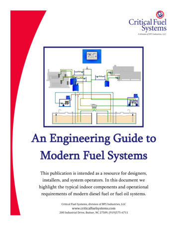
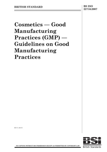
Coated Particle Fuel: Early History First developed in late 1950s tosupport Dragon reactor in UK(a)(b)(c)(d) Originated as single pyrocarbon layerto protect carbide kernels duringfabrication Quickly evolved in 1960s into moresophisticated coating designs toprovide fission product retention First demonstration reactors:§Dragon§Peach Bottom Unit 1§Arbeitsgemeinschaft Versuchsreaktor(AVR)P.A. Demkowicz et al., Coated particle fuel: Historical perspectives and current progress, J. Nucl.Mater. 515 (2019) 434-450(a) Early example of a BISO (bistructural isotropic) particle.(b) Particle with “Triplex” structure (porous buffer layerfollowed by laminar and columnar pyrocarbon layers). (c)Carbide particle with single PyC coating layer used in PeachBottom first core. (d) Fertile (Th,U)C2 particle used inDragon first charge, consisting of PyC-SiC-PyC structure.4
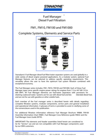
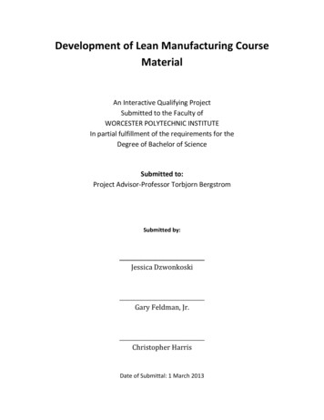
Modern TRISO Fuel Kernel (350-500 μm)§§ SiC ( 35 μm)UO2 or UCORetention of fissionproducts§§ Buffer ( 100 μm)§§§ 50% densepyrolytic carbonProvides space forfission gas andCO(g) accumulationAccommodatesfission recoilsMain structural layerPrimary coatinglayer for retainingnon-gaseous fissionproducts OPyC ( 40 μm)§§ IPyC ( 40 μm)§§§Protects kernel fromchloride during SiCdepositionSurface for SiCdepositionContributes to fissiongas retention§Contributes tofission gas retentionSurface for bondingto matrixProtects SiC layerduring handling5
TRISO Fuel Kernel Types Kernels are mechanically decoupled from the outer coating layers, givinggreat flexibility in kernel types HTGRs can use many fuel types§Fissile: UC2, PuO2, (Th,U)C2, (Th,U)O2, UO2, UCO§Fertile: ThC2, ThO2, UO2, UCO LEU UO2 is most widely used fuel type§Used in AVR (Germany), HTTR (Japan), HTR-10 and HTR-PM (China)§Extensive irradiation and heating test database from German HTGR Program§Reference fuel type for PBMR UCO offers improved fuel performance at higher fuel burnup§UCO selected as reference fuel design by X-energy§Several countries involved in the Generation IV International Forum (GIF) VeryHigh Temperature Reactor (VHTR) Fuel and Fuel Cycle (FFC) ProjectManagement Board are pursuing R&D on UCO fuel fabrication based on thefavorable US program results6
UO2 and UCO TRISO FuelUO2UCO(mixture ofUO2 and UCx) Different kernel Same coatings Utilized in modern pebble bed reactordesigns (burnup limited to 11% FIMA) Extensive development and testing sincethe 1970s in many countries Good fission product retention in thekernel, but results in formation of CO(g)during irradiation– Contributes to internal gas pressure– Kernel migration, CO corrosion of SiC Mitigates CO(g) formation Suited for higher burnup (up to 20% FIMAand beyond) and larger temperaturegradients in prismatic reactors Comes at the cost of lower retention ofsome fission products in the kernel Development primarily in the US since the1970s No large-scale, successful performancedemonstration through the early 2000s7
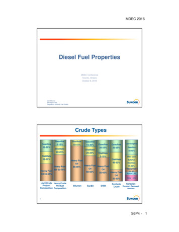
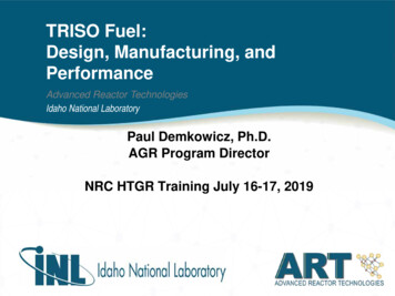
Tristructural Isotropic (TRISO) Coated Particle FuelPebble bedreactor(IPyC)(OPyC)PrismaticreactorTRISO particle60 mm25 mmSpherical fuel pebblesParticle designprovides excellentfission productretention in the fueland is at the heart ofthe safety basis forhigh temperaturegas reactors12 mmCylindrical fuelcompactsPrismatic graphite blocks
Emerging Reactor Designs Requiring TRISO Fuel Molten-salt-cooled reactors (FHR)§Most irradiation conditions are withinthe fuel performance envelopeexplored in the US AGR program,with some exceptions, e.g.: Power density may be higher Irradiation temperature may be lower§No data on TRISO performance insalt coolant Microreactors§Limited analyses on conceptual designs suggest that irradiation andaccident conditions are less severe than larger gas reactor designs9
Outline TRISO fuel background and history Fuel fabrication and quality control Fuel irradiation performance Fuel accident performance Fuel performance and fission product transportmodeling10
TRISO Fuel Fabrication: Process Overview20%U3O8Furnaces235U AmmoniaDonorGelationdry-calcine-sinter200 – 800 – 1600 CCarbonfor UCODissolutionKernelFluid-Bed CoaterCooling waterCoating tubeTemperaturemeasurement portWater-cooledcontainer wallThermalconductorWater-Wash(1300-1500 C)Pyrocarbon,SiC layersInsulationGas distributorElectrical cableGel-SphereGas inlet tubeOvercoatingFurnacesCompactcarbonize – heat treat800 – 1800 CCompactionParticles matrixCoatedparticlesTRISOParticle11
Coating Deposition Coatings are deposited onto kernels using a fluidized bedchemical vapor deposition furnace Coatings are applied using a continuous process Reactant gas mixture and temperature are controlled toobtain desired coating properties Coated particles are sorted by size and shape to removeunder- and over-sized particlesCoater convergingsection and gas nozzleIndustrial Scale 150mm Coater (BWXT)12
Fuel ElementsSpherical fuel elementsFuel sphere pressCylindricalfuel elementsFloating-body diecompact pressFinished fuel spheres60 mm 9,000 – 18,000 particles25 mm12 mm 1,500 – 4,100 particles13
US AGR Program Fuel Fabrication ProcessImprovements Reduced human interactions in the process§§§§Eliminated tabling with 3D sieving of coated particlesImproved matrix production (dry mixing and jet milling)Improved overcoating with automated fluidized bed overcoaterMulticavity compacting press with automatic fill Kernel fabrication§§Internal gelation to improve sphericityMethod of carbon addition modified to improve distribution of oxide andcarbide phases Improved chemical vapor deposition process control§§§§Argon dilution during SiC coatingCoater “chalice” and multiport nozzle to improve process yields ( 95%)Mass flow controllers to control gas flows during deposition of eachcoating layerImproved MTS vaporizer (SiC layer deposition)14
TRISO Fuel Quality Control Quality Control (QC) is the process used to verify that a product satisfiesthe design criteria QC for coated particle fuel includes:§Specifications on source materials, production processes, and process limits§Specifications on kernel, coating, and compact properties§Specifications on defect populations that may impact performance QC measurements of fuel properties are performed using statisticalsampling§Specifications are met to a 95% minimum confidence level§Statistics often force the average fuel quality to be significantly better than thespecifications IAEA Coordinated Research Program CRP-6§Fuel QA/QC round robin experimental study (also included HTGR fuelpredictive code benchmarking exercises)15
AGR Program Fuel Specifications for QC Specified criteria on both process conditions and fuel properties Acceptance stages for kernel batches, kernel composites, particle batches,particle composites, and compacts Specified mean values and/or critical limits on the dispersion for variableproperties, such as:––––Kernel diameterKernel stoichiometryLayer thicknessLayer density– Pyrocarbon anisotropy– Kernel and particleaspect ratio– SiC microstructure– Compact dimensions– Compact U loading– Dispersed U fraction– Compact impurity content Specified maximum defect fractions for attribute properties, such as:– SiC defects– IPyC/OPyC defects– Exposed kernel defects
Selected AGR-1 and AGR-2 Fuel Property MeansBAF True1.031.02AGR-2AGR-1 V3AGR-1 V2AGR-1 V11AGR-1 BIPyC density variantAGR-21.81.01AGR-1 V3AGR-2AGR-1 V3AGR-1 V21.91.8530AGR-1 V1AGR-2AGR-1 V3AGR-1 V235AGR-1 V180AGR-1 B363432378536AGR-1 V2381.04AGR-1 V139Density (g cm-3)40AGR-1 B90Specificationlimits for mean411.051.95AGR-210042Thickness (μm)Thickness (μm)Thickness (μm)105953843110AGR-1 V344IPyC anisotropy2AGR-1 V2115IPyC density40AGR-1 V145AGR-1 B120SiC thicknessAGR-1 BIPyC thicknessBuffer thickness Mean must be within the specification limits at 95% confidence AGR-1 and AGR-2 measured values typically lie well within thespecification range Note that some specifications were changed for AGR-2, based oncomputational modeling results on fuel behavior17
Improved Measurement Science Computer measurementsof thicknesses Greatly improved PyCanisotropy measurements Improved density measurementsusing better density column fluids18
Fuel Fabrication Summary TRISO fuel fabrication is a process that has matured over the last 50years Statistical sampling is used to verify fuel quality Specifications are met to at least a 95% confidence level US AGR program has implemented numerous fuel fabrication processand characterization method improvements19
Outline TRISO fuel background and history Fuel fabrication and quality control Fuel irradiation performance Fuel accident performance Fuel performance and fission product transportmodeling20
TRISO Fuel Performance Coating integrity– Layers remain intactto retain fissionproducts SiC layer failure:– Breach in the SiC layerwith at least onepyrocarbon layer intact– Release mostcondensable fissionproducts but retainfission gas TRISO layer failure: Fission product retention– Coating integrity– Retention in kernel– Diffusive transportthrough layers– Matrix retention– All three dense coatinglayers breached– Release of fission gasand condensable fissionproducts21
Fuel Failure MechanismsMechanical Pressure vessel failure Irradiation-induced PyC failureleading to SiC cracking IPyC-SiC partial debondingThermochemical Kernel migration SiC thermal decomposition Fission product attack of SiC Corrosion of SiC by CO Many of these mechanisms are precluded by improved particle design,improved manufactured fuel quality, and by operation of the fuel within itsintended performance envelope22
Fuel Failure Mechanisms SiC corrosion by CO(g)(in UO2 fuel) and fissionproducts (in UO2 andUCO fuel) is the primarycause of SiC layer failureobserved in modernTRISO fuel High-quality fuelmanufacture andlimitations on irradiationconditions (performanceenvelope) reduce failurefractions to acceptablelimits23
Irradiation TestingPrototype modular HTGRsPrototypical conditions (neutron spectrum and flux, burnupaccumulation rate)§ Long duration§ Difficult online measurement of fuel performance§ Less certainty on fuel temperature§Materials Test Reactors (MTRs)Accelerated irradiation times§ Measurement and control of fuel temperature§ Real-time measurement of fission product release§ Conditions may differ somewhat from HTGRs (neutronspectrum and flux, burnup accumulation rate)§24
Irradiation Testing of TRISO Fuel in MTRsAdvanced Test Reactor (ATR)Idaho National LaboratoryHigh Flux Reactor (HFR )Petten, Netherlands US DOE AGR compacts US NPR compacts German/EU fuel spheres INET and HTR-PM spheresHigh Flux Isotope Reactor (HFIR)Oak Ridge National LaboratoryMany other MTRshave been used totest TRISO fuelIVV-2M ReactorZarechny, Russia HTR-10 spheres US DOE TRISO fuels25
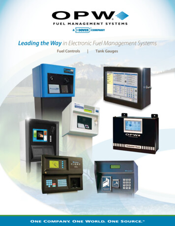
Irradiation Performance: R/B It is critical to have reliable measurement of fission gas release duringirradiation (real-time or intermittent through gas capture and analysis) Fission gas release rate to birth rate ratio (R/B) is the main metric of fuelperformance during irradiation Sweep gas (He Ne) injectedinto the capsules controlscapsule temperature andcarries fission gas to the FGMS Gamma spectrometers quantifyshort-lived Kr and Xe 135Xe-135mXe-137Xe-138Xe-139AGR-1 Fission Gas Monitoring System (FGMS)26
Irradiation Performance: R/B(cont’d) Sources of fission gas release:§Uranium contamination outside of intact SiC layers§Exposed kernel defects (as-fabricated)§Exposed kernels from in-service coating layer failure R/B provides information on the extent of coating failures during irradiation Release rate is a function of temperature and half-lifeAGR-1 Capsule 6à Data indicate zero as-fabricated exposed kernels or in-pile TRISO failures in this capsule27
Recent TRISO Fuel Irradiation Tests (2000 – Present)28
TRISO Fuel Post-Irradiation Examination and HighTemperature Accident Safety Testing Main objectives:§ Measure fission product retention during irradiation§ Measure fission product retention during high temperature post-irradiationheating§ Examine kernel and coating microstructures to understand irradiationinduced changes and the impact on fuel performance Both conventional and specialized equipment used for TRISO fuelexaminations29
In-Pile Fission Product Release EvaluationCapsule shellCompact matrix1.2.3.Graphite4.4321Release from kernel to coatinglayersRelease from coating layers tocompact matrixRelease from compact matrix tostructural graphiteRelease from structural graphiteto capsule shell (or reactorvessel)Look for fission products: In fuel compactsOn capsule componentsIn compact matrixIn individual particles30
Compact Deconsolidation-Leach-Burn-Leach AnalysisDeconsolidation hardwareIrradiated particlesand matrix debrisDisintegrate matrixand liberate looseparticlesElectrolyticdeconsolidationQuantify isotopeinventoriesNitric acid leachof particles andmatrix debris (X2)Oxidize carbon(matrix and OPyClayers)Air oxidation(“burn”) ofparticles and debrisQuantify isotopeinventoriesNitric acid leachof remainingmaterial (X2)Analyzeleachate for FPsand actinidesAnalyzeleachate for FPsand actinidesØ Process provides inventory of FPs andactinides in matrix outside of intact SiC31
Irradiated Particle Gamma Counting Gamma count individual particles to quantify FP inventory (Ag-110m, Cs-134,Cs-137, Eu-154, Ce-144) Identify particles with abnormal inventory Low Cs inventory indicates SiC failureand Cs releaseORNL IrradiatedMicrosphere GammaAnalyzer (IMGA)AGR-2 Compact 2-2-312009004 particles releasedCsPlotted 05Particle FrequencySummary for n 3151 0.00Measured versus Calculated 137Cs Inventory32
Studying failed particles greatly improvesunderstanding of fuel performanceAGR-1 Test TrainVertical SectionGamma scan toidentify cesiumhot spots andcompact locationGamma count tofind particles withlow cesiumretentionDeconsolidation toobtain 4,000 particlesfrom compactStudy particles with failed coatingsPlenumbetweenCapsulesIdentify particles with failed coatingsFuelCompactsX-ray tomographyto locate failuresCapsuledisassemblyIdentify compacts with leakers72 fuelcompactscontaining300,000particles inAGR-1irradiationX-rayMaterialography to exposedefective region for analysisOpticalSEMAdvancedmicroscopy tostudy coatinglayers in detailTEM50 nm33
Kernel and Coating Behavior During Irradiation: AGRParticlesUO2 10.5% FIMAAGR2-331 Kernel swelling and poreformationUCO 19.3% FIMAAGR1-413 Buffer densification andvolume reduction Separation of buffer andIPyC layersUCO 11.1% FIMAAGR2-513 Buffer fracture relatively common in UCOfuel particles Kernel can swell into gap Dependent on irradiation temperature andfast neutron fluence When buffer separates from IPyC, bufferfracture appears to have no detrimentaleffect on dense coating layers34
Fission Product BehaviorElementBehavior in TRISO FuelKr, Xe, I Retained by intact PyC or SiC layers Release is from uranium contamination and exposed kernels Kr and Xe are key indicator of failed TRISO layersCs Retained by SiC but released through intact PyC Key indicator of failed SiCSr Moderate retention in the fuel kernel Modest release through intact coatings (T 1100 C);significantly higher release for very high irradiationtemperatures Some retention in the compact matrixEu Similar to Sr, although evidence indicates slightly higherreleasesAg Significant release through intact SiC (T 1100 C) Relatively low retention in compact matrix35
Fission Product Release from Fuel Compacts: AGR-1and AGR-2 Examples1.0E 00Fission product release from AGR-1and AGR-2 UCO fuel compactsAGR-2 Capsule 2Peak irradiationtemperature 1360 C1.0E-011.0E-04 Sr and Eu can exhibit modestrelease; release is much higher withhigh in-pile temperatures (AGR-2Capsule 2 time-average peaktemperatures 1360 C)1.0E-05 High Ag release1.0E-02Release fraction Cs release is very low with intactSiC; higher releases are associatedwith a limited number of particleswith failed -110m36
Outline TRISO fuel background and history Fuel fabrication and quality control Fuel irradiation performance Fuel accident performance Fuel performance and fission product transportmodeling37
HTGR Accident Safety Testing of TRISO Fuel Temperature transients are relatively slow (days) Peak fuel temperatures are limited to 1600 C in modular HTGR designs Fuel particles are designed to withstand accident conditions while stillretaining key safety-significant fission products Total duration at peak temperatures is tens of hours, and only a smallfraction of the fuel in the core experiences temperatures near the peak. Assess fuel performance bypost-irradiation heating testswhile measuring fissionproduct release at 1600—1800 C38
AGR-1 and AGR-2 Safety Test Performance1.E 00 Low Kr release1.E-01 Modest Sr and Eu release(influenced by irradiationtemperature)1.E-02 Excellent UCO performance up to1800 C Low coating failure fractions(UCO) UO2 demonstrates much higherincidence of SiC failure due to COattack1600Relatively high Ag release;rapid release of inventoryin compact matrix14001200Modest Eu and Sr release; dominatedby inventory in compact matrix1.E-03Release fraction High Ag release (dominated byin-pile release from particles)AGR-1 UCO Compact 4-3-3 (1600 C)10001.E-04800Very low Kr 54Eu-155Sr-901.E-07Very low Csrelease when SiCremains intact1.E-081.E-090100200Elapsed Time (hours)300Temperature ( C) Low Cs release (dependent onintact SiC)400200039
Safety Test Data: German UO2 ResultsKr-85Kr-85Cs-13710 – 12% FIMA11 – 14% FIMA4 – 9% FIMAAll tests at 1600 C No TRISO failures at 1600 C TRISO failures occur aftershort periods at 1800 C No TRISO failures at1600 C with burnup 10% TRISO failures occur at1600 C with burnups 14%D.A. Petti et al., TRISO-Coated Particle Fuel Performance, in Konings R.J.M.,(ed.)Comprehensive Nuclear Materials (2012), vol. 3, pp. 151-213 Amsterdam: Elsevier. At 1600 C and burnup 10% FIMA, Cs releaseremains relatively low Increasing burnup andtemperature increases SiClayer degradation and Csrelease40
Cesium Release Results: AGR Program Safety Testing1.0E 00AGR-1 Cs-13413 – 19 % FIMA1.0E-01Release fraction1.0E-02 UCO fuel: relatively low Cs release;release 10-4 results from discrete SiClayer failure in 1 or more particles1800 C1.0E-031700 C1.0E-041.0E-051600 C1.0E-06 UO2 fuel: higher Cs release compared toUCO; driven by CO attack on the SiClayer causing more widespread SiCfailure1.0E-071.0E-081.0E 001.0E-01-50050 100 150 200 250 300 350 400 450Time at temperature (h)UO2 fuel( 10.5 % FIMA)1.0E-02Release fractionAGR-2 Cs-134UCO: 7.3 – 12.7 % FIMAUO2: 10.5 % 50100150200250Time at temperature (h)300350CO corrosion of SiC inUO2 fuel41
AGR UCO Particle SiC FailureIPyC cracking and SiC separationduring irradiation; no SiC failure Buffer densification in conjunction with strong bufferIPyC bonding can lead to IPyC cracking andseparation from SiC layer Allows localized attack of SiC layer by fissionproducts (especially Pd) Pd attack can eventually result in loss of FPretention by SiC layer Degradation is worse at higher safety testtemperaturesSiC failure during irradiationSiC degradation and failureafter 300 h at 1700 CIPyCSiC42
Fuel Design Safety ApproachExperimental coating failurefractions for AGR-1 AGR-2Specifications for particle defects and failure fractions“Maximum Expected”(upper limit at 95% confidence)SiC failuresTRISO failures“Design”As-Manufactured Fuel QualityHM contamination 1.0 x 10⁻⁵ 2.0 x 10⁻⁵ 5.0 x 10⁻⁵ 1.0 x 10⁻⁴Defective SiC1.0E-02In-Service TRISO FailureNormal operation 5.0 x 10⁻⁵ 2.0 x 10⁻⁴Accidents 1.5 x 10⁻⁴ 6.0 x 10⁻⁴ Establish specifications for as-manufacturedcontamination levels and particle defects thatcan lead to fission product releaseFailure fraction (95% confidence)ParameterNGNP – 750 C Core OutletTemperature1.0E-03Reactor design specfor TRISO failure1.0E-041.0E-05 Verify fuel quality with QC measurements Demonstrate failure fraction specifications aremet during fuel qualification irradiation andsafety testingAGR-1 and -2 TRISO failurefractions meet historic designspecifications with 10X43margin
Core Oxidation Accident scenarios in gas-cooled reactors can include air or steamingress into the core Specific conditions should be defined to the extent possible throughmodels (temperatures, durations, oxidant partial pressure) Core behavior under these conditions should be evaluated§Graphite and matrix oxidation§Fission product volatilization from matrix/graphite and exposed kernels§Coated particle integrity Graphite oxidation data is available in literature Limited data on matrix oxidation is available from previous tests US AGR program is performing dedicated testing to obtain necessarydata:§Matrix oxidation tests§Irradiated fuel heating tests in air and steam environments (starting 2020)44
Fuel Performance Summary There is an extensive database of TRISO irradiation testing in MTRs§§Historic testing in the US, German program testing, and othersRecent demonstrations include EU tests (archived German fuel), HTR-PMfuel, and US AGR program Modern TRISO fuel exhibits very low R/B values during irradiation (lowcoating failures) TRISO fuel FP release behavior is well-characterized Extensive accident testing database§Fuel withstands 300 h at temperatures of 1600 C and above with low failurerates Observed failure fractions are well below historic reactor design specs45
Outline TRISO fuel background and history Fuel fabrication and quality control Fuel irradiation performance Fuel accident performance Fuel performance and fission product transportmodeling46
Fuel Performance and Fission Product TransportModeling Predict coating behavior as a function of particle properties and irradiationconditions à Predict coating failure fractions Predict fission product release Optimize particle design Help establish fuel product specifications Numerous codes developed in various countries dating to the 1960sPARticle FUel ModElPARFUMEAGR program fuel performance modelingand analysis codeMechanistic codeThermal, mechanical, physico-chemicalbehavior of TRISO fuel particlesProbability of particle failureFission product fractional release47
Coating Stress Calculations and Particle FailureAnalysis Key inputs:§Fuel temperature, burnup, fast neutron fluence§PyC irradiation-induced creep and strain§SiC tensile strength and Weibull modulus§(Sensitivity studies indicate that many properties havelittle effect on particle failure)𝑃𝑃𝑓𝑓 1 𝑒𝑒 Particle failure probability based on Weibull statistics 𝑉𝑉𝜎𝜎 𝑚𝑚𝑑𝑑𝑑𝑑𝜎𝜎𝑜𝑜200Stress (MPa)1000-100-200IPyC-300-400SiC0.01.02.0Fluence (n/m2 x 1025)3.0Stress histories at inner radii of the IPyCand SiC layers for an uncracked particle.48
Fission Product Transport Modeling Fission product transport includes:§Release from failed particles§Release from uranium contaminationin the compact§Diffusive release through intactcoatingsUCO Requires FP diffusivities in:§Kernel§PyC§SiCUO2 Historic diffusivities come from UO2fuel fission product releaseobservations Current models tend to overpredictfission product release by asignificant marginResults of computational modeling code benchmark of fissionproduct release during high-temperature accident tests(B. Collin et al., Generation IV Benchmarking of TRISO FuelPerformance Models under Accident Conditions: Final Report,DRAFT)49
Summary TRISO fuel has a history spanning over 50 years High quality fuel can be fabricated to meet productspecifications TRISO fuel has excellent performance during normaloperation and accidents Fuel performance models predict behavior and tend to beconservative with respect to FP release50
Suggested ReadingGeneral TRISO Fuel 2010 HTGR Technology Course for the Nuclear Regulatory Commission P.A. Demkowicz et al., Coated particle fuel: Historical perspectives and current progress, J. Nucl. Mater. 515 (2019) 434450 M.J. Kania, H. Nabielek, H. Nickel, Coated Particle Fuels for High-Temperature Reactors, in Materials Science andTechnology, Wiley 2015. D.A. Petti et al., TRISO-Coated Particle Fuel Performance, in Konings R.J.M.,(ed.) Comprehensive Nuclear Materials(2012), vol. 3, pp. 151-213 Amsterdam: Elsevier. High Temperature Gas Cooled Reactor Fuels and Materials, IAEA, TECDOC-1645 (2010). K. Verfondern, H. Nabielek, J.M. Kendall, Coated particle fuel for high temperature gas cooled reactors, Nucl. Eng. Tech.39 (2007) 603-616. D.A. Petti et al., Key differences in the fabrication, irradiation and high temperature accident testing of US and GermanTRISO-coated particle fuel, and their implications on fuel performance, Nucl. Eng. Des. 222 (2003) 281-297. Fuel performance and fission product behavior in gas cooled reactors, IAEA, TECDOC-978 (1997).AGR Program Results P.A. Demkowicz et al., “Key results from irradiation and post-irradiation examination of AGR-1 UCO TRISO fuel,” Nucl. Eng.and Des. 329 (2018) 102–109. P.A. Demkowicz et al., AGR-1 Post Irradiation Examination Final Report, INL/EXT-15-36407, Idaho National Laboratory,2015. J.D. Hunn et al., “Post-Irradiation Examination and Safety Testing of US AGR-2 Irradiation Test Compacts,” Paper 10 inProceedings of the 9th International Topical Meeting on High Temperature Reactor Technology (HTR-2018), Warsaw,Poland, October 8–10, 2018. Available at https://www.osti.gov/biblio/1489588 J.D. Hunn et al., “Initial Examination of Fuel Compacts and TRISO Particles from the US AGR-2 Irradiation Test,” Nucl.Eng. and Des., 329 (2018) 89–101.51
Suggested Reading (cont.)HTR-PM Fuel C. Tang et al., Comparison of two irradiation testing results of HTR-10 fuel spheres, Nucl. Eng. Des. 251 (2012) 453-458. S. Knol et al., HTR-PM fuel pebble irradiation qualification in the high flux reactor in Petten, Nucl. Eng. Des. 329 (2018) 8288. D. Freis et al., Burn-up Determination and Accident Testing of HTR-PM Fuel Elements Irradiated in the HFR Petten,Proceedings of the 9th International Topical Meeting on High Temperature Reactor Technology (HTR-2018), 8-10 Oct.2018, Warsaw, PolandFuel Performance and Fission Product Transport Modeling J.J. Powers, B.D. Wirth, A review of TRISO fuel performance models, J. Nucl. Mater. 405 (2010) 74-82 G.K. Miller et al., PARFUME Theory and Model Basis Report, INL/EXT-08-14497, September 2018 W. F. Skerjanc, B. P. Collin, Assessment of Material Properties for TRISO Fuel Particles used in PARFUME, INL/EXT-1844631, August 201852
Kernel Fabrication Kernels are fabricated using a sol-gel process to form aspherical bead Dried spherical beads are heat treated to form the desiredmetal oxide and/or carbide phases and sinter the kernelFormKernelsAgeKernelsWash & DryKernelsCalcineKernelsSinterKernels54
Fuel Compact/Sphere FabricationNatural GraphiteSynthetic GraphiteTRISO ParticlesCylindricalRam and DieResin VolatilesPrepare MatrixPrecursorBinder ResinOvercoat ParticlesCompactOvercoatedParticlesCarbonizeMatrix andHeat-treatSphericalRubberFormImpurities55
support Dragon reactor in UK Originated as single pyrocarbon layer to protect carbide kernels during fabrication Quickly evolved in 1960s into more sophisticated coating designs to provide fission product retention First demonstration reactors: § Dragon § Peach Bottom Unit 1 § Arbeitsgemeinschaft Versuchsreaktor (AVR) 4