Transcription
Head/Neck801Lateralized Odontoid in Plain Film Radiography: Sign ofFractures? – A Comparison Study with MDCTAuthorsS. Keller, K. Bieck, M. Karul, B. Schönnagel, G. Adam, C. Habermann, J. YamamuraAffiliationDepartment of Diagnostic and Interventional Radiology, University Hospital Hamburg Eppendorf, Hamburg, GermanyKey wordsZusammenfassungAbstract"!!Ziel: Die Evaluation der Wertigkeit von konventionell-radiologischen Messungen zur Detektioneiner Densfraktur im Vergleich zur Schnittbildgebung (CT).Material und Methoden: 79 Patienten (männlich31, weiblich 48, Alter 60 26 Jahre), die aufgrundeiner Lateralisation des Dens axis im konventionellen Röntgen (a. p./lat. Projektion und Denszielaufnahme) eine CT-grafische weiterführende Untersuchung der Halswirbelsäule erhielten, wurdenausgewertet. Dabei wurden verschiedene Messparameter wie die atlantodentale Distanz, Winkelmessungen zur Evaluation einer Densangulierungund die Beurteilung des HinterkantenalignementsC0-C3 in den o. g. Projektionen im Vergleich zurCT der HWS als Standard ausgewertet. Die statistische Auswertung zur Beurteilung signifikanterUnterschiede zwischen gesunden Patienten undPatienten mit CT-grafisch gesicherter Densfrakturerfolgte mit dem Discriminatory power Test.Ergebnisse: 8 von 79 (10,1 %) der untersuchtenPatienten wiesen eine Fraktur des Dens axis auf.In 6 Patienten wurde die Fraktur bereits im konventionellen Röntgen gesichert. Weder Messungender atlantodentalen Distanz (Denszielaufnahme0,49 0,13 cm vs. 0,47 0,13 cm, lat. 0,16 0,09 cmvs. 0,12 0,09 cm), noch die Winkelmessungen(Denszielaufnahme 87,4 2,8 vs. 83,8 3,5 lat.88,5 6,2 vs. 88,6 6,3 ) oder die Evaluation desWirbelkörperalignements zeigten signifikante Unterschiede zwischen den gesunden Patienten undden Patienten mit Densfraktur.Schlussfolgerung: Die Dezentralisierung des Densaxis im konventionellen Röntgen bei Patienten mitVerdacht auf eine Densfraktur ist aufgrund dergroßen physiologischen Variabilität kein sicheresZeichen für eine Fraktur. Bei klinischem Verdachtauf eine Densfraktur ist eine native Computertomografie der HWS das Mittel der Wahl.Purpose: To evaluate X-ray standards for the detection of odontoid fractures. Summary of background data: Cervical spine fractures are a common finding in emergency medicine, accountingfor 1 – 3 % of injuries. Involvement of the C1 / C2complex is found in 25 % of cases, affecting theodontoid peg in 55 – 80 %. Regarding the consequences of missed fractures, radiographic techniques built the groundwork for further treatmentprocedures. As standardized X-ray measurementshave not been established, the incidence of unrecognized cervical spine fracture is expected to be upto 20 %. The establishment of X-ray-based guidelines is also limited by the presumed low specificity and sensitivity of distance measurementscaused by rotational distortion which leads to a rising popularity of CT.Materials and Methods: 79 (age 60 26 yrs) patients with lateralization of the odontoid processon conventional plain film radiography (anteroposterior, lateral, and open mouth odontoid process view projection) were examined. The distance between the odontoid process and lateralmass of C1, angles of vertical odontoid line andbasis of C2 were measured in the ap view. In thelateral view, dorsal alignment and atlantodentaldistance were assessed. MDCT examinationswere used as a reference. Discriminatory powertest was applied to assess significance.Results: 8/79 (10.1 %) odontoid process fractureswere found. Diagnosis was achieved on conventional radiographs in 6 patients. Neither distanceand angle measurements between odontoid andC1 nor the dorsal alignment of the vertebral bodies differed significantly between healthy and affected patients.Conclusion: Decentralization of the odontoid process is not necessarily an indirect sign for its fracture. In patients with suspected injury of the spine trauma CT bliographyDOI http://dx.doi.org/10.1055/s-0035-1553237Published online: 26.6.2015Fortschr Röntgenstr 2015; 187:801–807 Georg ThiemeVerlag KG Stuttgart · New York ·ISSN 1438-9029CorrespondenceDr. Sarah KellerZentrum für Radiologie undEndoskopie, Klinik und Poliklinikfür Diagnostische undInterventionelle artinistr. 5220255 HamburgGermanyTel.: 49/178/5 56 60 54Fax: 49/40/7 41 05 67 99s.keller@uke.deKeller S et al. Lateralized Odontoid in Fortschr Röntgenstr 2015; 187: 801–807This document was downloaded for personal use only. Unauthorized distribution is strictly prohibited.Dezentralisation des Dens axis in der Denszielaufnahme alssicheres Zeichen einer Fraktur? Eine Vergleichsstudie mitder Computertomografie
Head/NeckKernaussagen: Auch die metrische Evaluation des zervikalen Alignementsund der physiologischen Deviation des Dens axis im konventionellen Röntgenbild ermöglicht keinen sicheren Frakturausschluss. Bei HWS-Traumata die eine Bildgebung erfordern ist weiterhinein primäres MDCT indiziert.odontoid process, an MDCT scan might be the method of choiceto rule out a fracture.Key points: Due to the wide physiological variety of odontoid process position, even a detailed metric analysis of cervical alignment andodontoid process angulation in X-ray scans is not able to facilitate the diagnosis of odontoid process fractures. In the case of cervical spine trauma, which necessitate medicalimaging, a primary MDCT scan should be the method of choice.Citation Format: Keller S., Bieck K., Karul M. et al. Lateralized Odontoid in PlainFilm Radiography: Sign of Fractures? – A Comparison Studywith MDCT. Fortschr Röntgenstr 2015; 187: 801–807IntroductionMaterials and Methods!!With an overall occurrence of 1 – 3 % in trauma cases, cervicalspine fractures, accounting for up to two-thirds of spinal cord injuries, are a relatively common finding [1, 2]. Involvement of theC1 / C2 complex is found in 19 – 25 % of cases, affecting the odontoid peg in 55 – 80 % [1, 3, 4]. Anderson and D'Alonzo definedthree types of odontoid process fractures regarding the fracturelocation [5]. Type I fractures are considered stable, only affectingthe tip of the odontoid process. Types II and III encompass horizontal fractures through the odontoid process, either localizedbetween the level of the transverse ligament and the C2 vertebralbody (type II) or extending into C2 (type III) [5, 6].Regarding the potentially devastating consequences of missedfractures or disco-ligamentous injuries, radiographic imagingtechniques of the upper cervical spine are crucial for injury detection and classification, building the groundwork for furthersurgical stabilization or non-operative treatment procedures[7 – 9]. Nevertheless, the incidence of delayed or missed diagnosisat the cervical spine in critically injured trauma patients is expected to be relatively high, ranging from 5 – 20 % [10 – 12]. Onereason might be the lack of generally approved guidelines andprotocols for the clinical and radiological assessment of patientssuffering cervical spine trauma [13 – 15]. However, except onemethod postulated by Carlson et al., measuring the displacementand angulation by drawing lines along the anterior aspect of thedens fragment and C2 body in the lateral cervical radiography ormid sagittal CT reconstruction, radiographic measurementstandards for the assessment of angulation or displacement ofodontoid fractures have not been established so far [16, 17]. Onereason for the lack of standardized X-ray based methods andguidelines might be given by the presumed limited specificityand sensitivity of distance measurements in projection radiography caused by rotational distortion or parallax error, accountingfor the rising popularity of computed tomography (CT) scan fortrauma evaluation of the upper cervical spine [18 – 22].Therefore, the aim of our study was to evaluate the finding ofodontoid lateralization for the diagnosis of odontoid fracturesand to assess whether an additional CT scan can be avoided especially in the light of the rising expenses and radiation exposureassociated with this effort.Patient population79 consecutive cases, which received conventional X-ray scans inlateral and anteroposterior projection upon cervical spine trauma between January 2010 and April 2011, were retrospectivelyreviewed. All patients (n 79) underwent multi-detector computed tomography (MDCT) to assess an odontoid process fracturesuspected on plain film radiography. Patients under the age of16 and patients with diagnosed ligament injury in additionalperformed MRI scans were excluded. Measurement standardsfor the assessment of odontoid peg lateralization were appliedon standard radiographs. The patient s clinical and anamnesticfindings upon examination were retrieved from the medical records. The patient cohort undergoing cervical X-ray scan aftertrauma history was characterized by a mean age of 51.7 years,with a range of 16 to 96 years and gender distribution of 38 men" Table 1 summarizes the major clinical characand 60 women. teristics of the patient population.Radiological Examination – Plain RadiographsPatients were examined using a high-end, flat detector directdigital system (Digital Diagnost; Philips, Best, The Netherlands).X-ray imaging of the cervical vertebrae (C 1 – 7) was performedin two projections (anteroposterior and lateral view) coveringC1 to C7. The central ray was focused to C4. The imaging parameters were: 20 mAs, 100 cm FFD, and 81 kVp for anteroposterior (AP) projection, and 85kVp for lateral projection. In addition,an open mouth odontoid process view projection was performed.In the AP projection patients were facing the X-ray tube and wereTable 1 Clinical and epidemiological characteristics of patient cohort(n 79).Tab. 1 Klinische und epidemiologische Charakteristika der Studiengruppe(n 79).patient popu-no injuryfracturelation (n 79)(n 71)(n 8)gender31 (m) 48 (f)31 (m) 42 (f)2 (m) 6 (f)average age60.3 25.6y59.2 25.5y69.9 26.3ycervical pain23 (24.0 %)21/71 (29.5 %)2/8 (25 %)X-rayKeller S et al. Lateralized Odontoid in Fortschr Röntgenstr 2015; 187: 801–807op67 (84.8 %)63/71 (88.7 %)4/8 (50.0 %)ap79 (100.0 %)71/71 (100.0 %)8/8 (100.0 %)lat79 (100.0 %)71/71 (100.0 %)8/8 (100.0 %)MDCT79 (90.0 %)71/71 (100 %)8/8 (100 %)This document was downloaded for personal use only. Unauthorized distribution is strictly prohibited.802
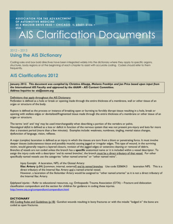
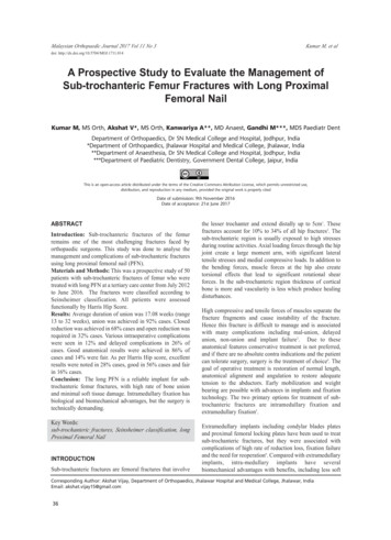
Head/NeckImaging and measurement methodsMeasurement values were determined using a radiology information system – picture archiving and communication system(RIS-PACS system) (Centricity RIS-i 4.2 Plus, GE General Electric Company, USA).Odontoid process projection (op)3 parameters were determined in 67 patients receiving an additional odontoid process view:For the right and left distance between the odontoid process andthe lateral mass of C1, a horizontal line was drawn in the regionin which the odontoid process showed the smallest diameter" Fig. 1a). Furthermore, two angles, one drawing a vertical line( in the middle of the odontoid peg and a horizontal line from the" Fig. 1b) or the horizontal posiright to left lateral mass of C2 ( "tion ( Fig. 1c) were determined.Anterior-posterior (ap) projectionAnterior-posterior projection scans were available in all patientsundergoing X-ray scan after cervical spine trauma. Dens decentralization was determined measuring the right to left distance be" Fig. 2a).tween central odontoid process and lateral mass of C1 ( Fig. 1 Assessed parameters in odontoid process view. Above: diagrammed layout, below: X-ray pattern. a Right to left distance between odontoidprocess and lateral mass C1. b Angle of vertical odontoid line and horizontalline between right to left lateral mass C2. c Angle of vertical odontoid lineand horizontal position." Fig. 1), angles of the cenBased on the method described above ( " Fig. 2b) or the horitral vertical odontoid line and basis of C2 ( " Fig. 2c) were obtained.zontal position ( Lateral (lat) projectionLateral projections were conducted in all patients and were usedfor both evaluation of dorsal alignment of the vertebral body" Fig. 3a) and the determination of anterior and posterior atlan( " Fig. 3b). Furthermore, the physiological potodental distance ( " Fig. 3c), angles of lateral odontoidsition between C2 and C3 ( " Fig. 3 d), and posterior line of odonvertical line and C2 basis ( " Fig. 3e) were analyzed.toid process and C2 vertebral body ( MDCTThe MDCT examinations were performed on a 256-detector rowcomputed tomography (CT) scanner (Brilliance iCT; PhilipsHealthcare, Best, The Netherlands). The images were obtainedafter a sagittal scout MDCT from C1 to C7 while the patientswere positioned on the table and held their breath. The imagingparameters were: 120 kVp, 250 mAs/slice, pitch 0.985 and collimation 2 mm 128 mm 0.625 mm. Midline sagittal and coronalimages were reformatted from the axial datasets with a slicethickness of 3 mm. The images in any case were viewed at a window level of 1000 Hounsfield units (HU) and a width of 2500 HU.Statistical analysisFor statistical analysis a robust discriminatory power test wasused. In this test, the discriminatory power D is calculated as astandardized mean difference (similar to a z-score). Statisticalsignificance can be calculated from D by the degree of overlap(classification error) of two groups for a certain parameter distri-Abb. 1 Untersuchte Parameter in der Dens Zielaufnahme. Oben: Schematische Skizze. Unten: Röntgenaufnahme. a Laterale distanz zwischenDens axis und Massa lateralis C1. b Winkel der Dens axis Vertikalen zurhorizontalen Linie zwischen der rechten und linken Massa lateralis C2.c Winkel der Dens axis Vertikalen zur Horizontalen.Keller S et al. Lateralized Odontoid in Fortschr Röntgenstr 2015; 187: 801–807This document was downloaded for personal use only. Unauthorized distribution is strictly prohibited.positioned supine on the table bucky with arms at their sides.The midsagittal plane was aligned. The patients’ knees wereflexed up, with the soles of their feet flat on the table in order toreduce the curve of the lower back. In the left lateral position thearms were put to the front. The spine had to be in a position parallel to the table bucky. Positioning markers and gonadal shielding were used. To absorb excess scatter, radiation shielding wasplaced on the table.803
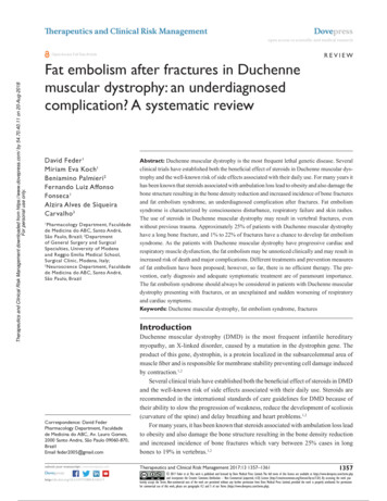
Head/NeckFig. 2 Assessed parameters in anterior-posterior (ap) projection. Above:diagrammed layout, below: X-ray pattern. a Right to left distance betweencentral odontoid process and lateral mass of C1. b Angle of vertical odontoid process line and basis of C2. c Angle of vertical odontoid process lineand horizontal position.bution, but not necessarily with a common variance [23]. We alsoconfirmed the test outcomes by the non-parametric Median test(Analyze-it Software Ltd, Leeds, UK), which checks the differenceof two (or more) median values.Results!From 79 patients examined, 8 patients suffered from odontoidprocess fractures. In 71/79 patients no injury was detected. Only2 patients (25 %) with diagnosed dens fracture admitted to cervical pain, compared to 21/71 (29.5 %) patients without overt densfracture. 67/79 patients (84.8 %) received an open mouth odontoidprocess projection. Here, the average distance between odontoid" Fig. 1a, 4a) was 0.49 0.13 cm inprocess and lateral mass of C1 ( intact and 0.47 0.13 cm in fractured processes. The average anglevalue of the vertical odontoid line and horizontal line between" Fig. 1b, 4a) was 87.4 2.8 versusright to left lateral mass ( 83.8 3.5 and 86.7 2.7 versus 86.5 1.9 between the vertical" Fig. 1c, 4a). Anteroodontoid process line and the horizontal ( posterior projection scans were available in all 79 patients. Thedistance between the odontoid process and C1 vertebral body" Fig. 2a, 4b) was 0.47 0.11 cm in healthy versus 0.37 0.11 cm( Keller S et al. Lateralized Odontoid in Fortschr Röntgenstr 2015; 187: 801–807Abb. 2 Parameter in der ap Projektion. Oben: Schematische Skizze.Unten: Röntgenaufnahme. a Rechte und linke Distanz zwischen Dens axisund Massa lateralis C1. b Winkel der Dens axis Vertikalen und horizontalerLinie zur Basis von C2. c Winkel der Dens axis Vertikalen zur Horizontalen.in fractures and the angles between the odontoid process and ba" Fig. 2b, 4b) as well as the odontoid process and horizonsis C1 ( " Fig. 2c, 4b) were 87.8 2.6 in healthy versus 86.1 2.2 intal ( fractures and 86.2 3.6 versus 82.4 5.2 , respectively. Lateralprojections were also taken in all 79 patients. Dorsal alignment" Fig. 3a) was found to be disrupted in 4/71 healthy patients( (6.0 %) versus 2 (25 %) patients with overt dens fracture. Physiological position (lateral angle between horizontal) of C2/3" Fig. 3c) was normal in all patients. The atlantodental distance( " Fig. 3b, 4c) was 0.16 0.09 cm versus 0.12 0.09 cm and the an( gle between the posterior odontoid process vertical and posterior" Fig. 3e, 4c) was 10.8 7.3 versus 8.5 12.2 .C2 vertebral body ( The angle between the central odontoid vertical line and the C2" Fig. 3 d) measured 88.5 6.2 versusvertebral body horizontal ( 88.6 6.3 and deviated either in the frontal or dorsal direction. " Table 2 summarizes the radiographic measurement values obtained in all projections. In all measured parameters obtained indifferent projections, no significant changes were found betweenhealthy patients and patients suffering odontoid fracture.This document was downloaded for personal use only. Unauthorized distribution is strictly prohibited.804
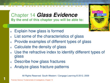
Head/Neck805Fig. 3 Measurements in lateral projection (lat)Above: diagrammed layout, below: X-ray pattern.a Dorsal alignment of vertebral bodies. b Anteriorand posterior atlantodental distance. c Physiologicalposition between C2/C3. d Angle of odontoid vertical line and C2 basis. e Posterior odontoid processline and C2 vertebral body angle.Table 2 Plain film radiographic measurement values in odontoid process,anteroposterior and lateral projection of healthy and fractured dens axis.Tab. 2 Erhobene Messparameter des frakturierten versus intakten Dens axisim konventionellen Röntgen (Denszielaufnahme, a. p., und lat. Projektion).projectionopaplatno fracturefracturedistanceFig. 1a/4aangleFig. 1b/4aangleFig. 1c/4c0.49 0.1387.4 2.886.7 2.70.47 0.1383.8 3.586.5 1.9distanceFig. 2a/4bangleFig. 2b/4bangleFig. 2c/4c0.47 0.1187.8 2.686.2 3.60.37 0.1186.1 2.282.4 5.2distanceFig. 3b/4cangleFig. 3 dangleFig. 3e/4c0.16 0.0988.5 6.210.8 7.30.12 0.0988.6 6.38.5 12.2Discussion!Cervical spine fractures occur in 1 – 3 % of trauma cases and cancause devastating long-term physical impairment if underdiagnosed or misteated in the clinical course. Thus, reliable radiographic measurement standards are indispensable for the evaluation ofcervical integrity, especially in light of the sometimes difficult analysis of the dens axis shape and articulation.There is common agreement about certain radiographic signsassociated with odontoid process fractures which can be easilydetected and evaluated in conventional X-ray scans. These rediographic signs include the assessement of the anterior and posterior atlantodental interval (ADI and PADI) in the lateral projection,the lateral mass displacement in the open mouth odontoid process view, and the thickness and appearance of the prevertebralsoft tissue (PVST) [16, 24, 25]. However, available guidelines,which evauated the sensitivity of plain film radiography afterspinal trauma, recommend MDCT as the preferred imagingprocedure [26]. To prevent the MDCT-associated disadvantagesKeller S et al. Lateralized Odontoid in Fortschr Röntgenstr 2015; 187: 801–807This document was downloaded for personal use only. Unauthorized distribution is strictly prohibited.Abb. 3 Parameter in der lateralen Projektion (lat).Oben: Schematische Skizze. Unten: Röntgenaufnahme. a Wirbelkörperhinterkantenalignement.b Vordere und hintere allantodentale Distanz.c Physiologische Position zwischen C2/3. d Winkelzwischen Dens axis Vertikaler und Basis C2. e Winkelzwischen hinterer Dens axis Linie und C2 Wirbelkörper.
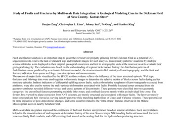
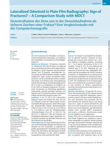
Head/NeckFig. 4 Differences between measured parametersin healthy patients and patients presenting withdens fracture. a Odontoid process projection, distance dens C1 and angle dens basis C1/dens horizontal. b ap projection, distance dens C1 vertebralbody and angle dens basis C2/dens horizontal.c Lateral projection, distance dens basis and angleposterior dens C2 vertical.Abb. 4 Unterschiede zwischen erhobenen Parametern in Gesunden versus Patienten mit DensFraktur. a Dens Zielaufnahme. Distanz Dens C1,Winkel Dens Basics C1 und Dens Horizontale.b Ap Projektion. Distanz Dens C1, WinkelDens Basis C2 und Dens Horizontale. c LateraleProjektion. Atlantodentale Distanz. Winkel Hinterkante Dens C2.Fig. 5 a – d Lateralization of the odontoid peg inplain film radiography as sign of suspected fracture.Additionally performed MDCT scan provesphysiological lateralization without fracture.Abb. 5 a – d Lateralisation des Dens axis in derProjektionsradiografie als indirektes Zeichen einerDensfraktur. Additives MDCT der Halswirbelsäulebestätigt die physiologische Dezentralisation ohneFrakturnachweis.of higher radiation exposure and higher financial expenses, theaim of this study was to evaluate this conventional imagingmethod, based on standardized measurements in conventionalX-ray scans of the cervical spine. Our data indicate that there areKeller S et al. Lateralized Odontoid in Fortschr Röntgenstr 2015; 187: 801–807no reliable differences on plain films of patients suffering from adens axis fracture compared to patients with C1 / C2 integrity.These findings might be explained by the overt physiological distance and angle variation in healthy patients, contradicting theThis document was downloaded for personal use only. Unauthorized distribution is strictly prohibited.806
primary assumption of enhanced dens location variance in theinterplay with C1 vertebral structures due to disrupture of dens" Fig. 5). Furthermore intraaxis alignment caused by fracture ( and interobserver variability might additionally introduce measurement errors in conventional radiography as well as computedtomography [24]. Our results coincide with previous studies reporting a 65 % to 90 % (three view cervical spine series) sensitivityof plain radiography versus 98 % to 100 % of computed tomography for the screening of cervical spine injury [27 – 30]. Despitethat, the higher susceptibility of plain radiography techniques forexternal confounding factors, especially in agitated or immobilized patients might additionally lower the quality and subsequent assessment of cervical structures [9, 31]. The physiologicalanatomical variation of cervical structures, especially regardingthe C1 / C2 articulation and interplay hampers the reliability offixed measurement parameters in plain radiographic trauma series, thereby posing a risk of mis- or underdiagnosis of odontoidprocess fractures. Referring to the adavantages of MDCT in patients with suspected cervical spine fractures, such as the highersensitivity and better assessability of the connected soft tissue,previous studies recommend replacement of plain films byMDCT to circumvent the potentially devastating consequencesof undetected cervical spine fractures.Conclusion!Due to the wide variety of physiological odontoid process positions, X-ray-based metric analysis of deviations in cervical alignment and odontoid process angulation don’t facilitate a definitediagnosis of cervical spine fractures. In patients with suspectedinjury of the cervical spine including the odontoid process, adose-adapted MDCT scan of the cervical spine should be emphasized to prevent the risk of overlooking potentially harmful injuries.References01 Pratt H, Davies E, King L. Traumatic injuries of the c1 / c2 complex: computed tomographic imaging appearances. Curr Probl Diagn Radiol2008; 37: 26 – 3802 Clark CR, White AA 3rd. Fractures of the dens. A multicenter study. JBone Joint Surg Am 1985; 67: 1340 – 134803 Greene KA et al. Acute axis fractures. Analysis of management and outcome in 340 consecutive cases. Spine (Phila Pa 1976) 1997; 22: 1843 –185204 Chutkan NB, King AG, Harris MB. Odontoid Fractures: Evaluation andManagement. J Am Acad Orthop Surg 1997; 5: 199 – 20405 Anderson LD, D'Alonzo RT. Fractures of the odontoid process of the axis.J Bone Joint Surg Am 1974; 56: 1663 – 167406 Elgafy H et al. Treatment of displaced type II odontoid fractures in elderly patients. Am J Orthop (Belle Mead NJ) 2009; 38: 410 – 41607 Mulkens TH et al. Comparison of low-dose with standard-dose multidetector CT in cervical spine trauma. AJNR Am J Neuroradiol 2007; 28:1444 – 145008 Kim DH et al. Early predictive value of supine and upright X-ray films ofodontoid fractures treated with halo-vest immobilization. Spine J2008; 8: 612 – 61809 Holmes JF, Akkinepalli R. Computed tomography versus plain radiography to screen for cervical spine injury: a meta-analysis. J Trauma 2005;58: 902 – 90510 Davis JW et al. The etiology of missed cervical spine injuries. J Trauma1993; 34: 342 – 34611 Reid DC et al. Etiology and clinical course of missed spine fractures.J Trauma 1987; 27: 980 – 98612 Gerrelts BD et al. Delayed diagnosis of cervical spine injuries. J Trauma1991; 31: 1622 – 162613 Albrecht RM et al. Evaluation of cervical spine in intensive care patientsfollowing blunt trauma. World J Surg 2001; 25: 1089 – 109614 Grossman MD et al. National survey of the incidence of cervical spineinjury and approach to cervical spine clearance in U. S. trauma centers.J Trauma 1999; 47: 684 – 69015 Harris MB et al. Evaluation of the cervical spine in the polytrauma patient. Spine (Phila Pa 1976) 2000; 25: 2884 – 2891 discussion 289216 Bono CM et al. Measurement techniques for upper cervical spine injuries: consensus statement of the Spine Trauma Study Group. Spine(Phila Pa 1976) 2007; 32: 593 – 60017 Heller JG, Carlson GD. Odontoid Fractures. In: Spine State of the Art Reviews. Philadelphia, Pennsylvania: Hanley and Belfust Inc; 199118 Platzer P et al. Clearing the cervical spine in critically injured patients:a comprehensive C-spine protocol to avoid unnecessary delays in diagnosis. Eur Spine J 2006; 15: 1801 – 181019 Herzenberg JE et al. Emergency transport and positioning of youngchildren who have an injury of the cervical spine. The standard backboard may be hazardous. J Bone Joint Surg Am 1989; 71: 15 – 2220 Sun PP et al. Spectrum of occipitoatlantoaxial injury in young children.J Neurosurg 2000; 93: 28 – 3921 Barrett TW et al. Injuries missed by limited computed tomographicimaging of patients with cervical spine injuries. Ann Emerg Med2006; 47: 129 – 13322 McCulloch PT et al. Helical computed tomography alone comparedwith plain radiographs with adjunct computed tomography to evaluate the cervical spine after high-energy trauma. J Bone Joint Surg Am2005; 87: 2388 – 239423 Penrose LS. Measurement of pleiotropic effects in phenylketonuria. Annals of eugenics 1951; 16: 134 – 14124 Bono CM et al. Observer variability of radiographic measurements ofC2 (axis) fractures. Spine (Phila Pa 1976) 2010; 35: 1206 – 121025 Rojas CA et al. Normal thickness and appearance of the prevertebralsoft tissues on multidetector CT. AJNR Am J Neuroradiol 2009; 30:136 – 14126 Van Goethem JW et al. Imaging in spinal trauma. Eur Radiol 2005; 15:582 – 59027 Harrison DE et al. Cobb method or Harrison posterior tangent method:which to choose for lateral cervical radiographic analysis. Spine (PhilaPa 1976) 2000; 25: 2072 – 207828 Radcliff KE et al. Comprehensive computed tomography assessment ofthe upper cervical anatomy: what is normal? Spine J 2010; 10: 219 –22929 Widder S et al. Prospective evaluation of computed tomographic scanning for the spinal clearance of obtunded trauma patients: preliminaryresults. J Trauma 2004; 56: 1179 – 118430 Schleehauf K et al. Computed tomography in the initial evaluation ofthe cervical spine. Ann Emerg Med 1989; 18: 815 – 81731 Vandemark RM. Radiology of the cervical spine in trauma patients:practice pitfalls and recommendations for improving efficiency andcommunication. Am J Roentgenol Am J Roentgenol 1990; 155: 465 –472Keller S et al. Lateralized Odontoid in Fortschr Röntgenstr 2015; 187: 801–807807This document was downloaded for personal use only. Unauthorized distribution is strictly prohibited.Head/Neck
(RIS-PACS system) (Centricity RIS-i 4.2 Plus, GE General Elec-tric Company, USA). Odontoid process projection (op) 3 parameters were determined in 67 patients receiving an addi-tional odontoid process view: For the right and left distance between the odontoid process and the lateral mass of C1, a horizontal line was drawn in the region