Transcription
W331-Z00AMD Ryzen Tower Entry WorkstationUser ManualRev. 1.0
Copyright 2021 GIGA-BYTE TECHNOLOGY CO., LTD. All rights reserved.The trademarks mentioned in this manual are legally registered to their respective owners.DisclaimerInformation in this manual is protected by copyright laws and is the property of GIGABYTE.Changes to the specifications and features in this manual may be made by GIGABYTE withoutprior notice. No part of this manual may be reproduced, copied, translated, transmitted, orpublished in any form or by any means without GIGABYTE's prior written permission.Documentation ClassificationsIn order to assist in the use of this product, GIGABYTE provides the following types of documentation: User Manual: detailed information & steps about the installation, configuration and use of thisproduct (e.g. motherboard, server barebones), covering hardware and BIOS.User Guide: detailed information about the installation & use of an add-on hardware orsoftware component (e.g. BMC firmware, rail-kit) compatible with this product.Quick Installation Guide: a short guide with visual diagrams that you can reference easily forinstallation purposes of this product (e.g. motherboard, server barebones).Please see the support section of the online product page to check the current availability of thesedocuments.For More InformationFor related product specifications, the latest firmware and software, and other information please visit our website athttp://www.gigabyte.comFor GIGABYTE distributors and resellers, additional sales & marketing materials are available from our resellerportal: http://reseller.b2b.gigabyte.comFor further technical assistance, please contact your GIGABYTE representative or visithttps://esupport.gigabyte.com/ to create a new support ticketFor any general sales or marketing enquiries, you may also message GIGABYTE server directly by email:server.grp@gigabyte.com
ConventionsThe following conventions are used in this user's guide:NOTE!Gives bits and pieces of additionalinformation related to the current topic.CAUTION!Gives precautionary measures toavoid possible hardware or software problems.WARNING!Alerts you to any damage that mightresult from doing or not doing specific actions.
Warnings and CautionsBefore installing, be sure that you understand the following warnings and cautions.WARNING!To reduce the risk of electric shock or damage to the equipment: Do not disable the power cord grounding plug. The grounding plug is an important safetyfeature. Plug the power cord into a grounded (earthed) electrical outlet that is easily accessible at alltimes. Unplug all the power cords from the power supplies to disconnect power to the equipment. Shock Hazard! Disconnect all power supply cords before servicing. Do not route the power cord where it can be walked on or pinched by items placed against it.Pay particular attention to the plug, electrical outlet, and the point where the cord extends fromthe server.WARNING!To reduce the risk of personal injury from hot surfaces, allow the drivesand the internal system components to cool before touching them.CAUTION! Do not operate the system for long periods with the access panel open or removed. Operating the system in this manner results in improper airflow and improper cooling that can lead tothermal damage. Danger of explosion if battery is incorrectly replaced. Replace only with the same or equivalent type recommended by the manufacturer. Dispose of used batteries according to the manufacturer’s instructions.
Electrostatic Discharge (ESD)CAUTION!ESD CAN DAMAGE DRIVES, BOARDS, AND OTHER PARTS. WE RECOMMEND THAT YOUPERFORM ALL PROCEDURES AT AN ESD WORKSTATION. IF ONE IS NOT AVAILABLE,PROVIDE SOME ESD PROTECTION BY WEARING AN ANTI-STATIC WRIST STRAP ATTACHED TO CHASSIS GROUND -- ANY UNPAINTED METAL SURFACE -- ON YOUR SERVERWHEN HANDLING PARTS.Always handle boards carefully. They can be extremely sensitive to ESD. Hold boards only bytheir edges without any component and pin touching. After removing a board from its protectivewrapper or from the system, place the board component side up on a grounded, static free surface. Use a conductive foam pad if available but not the board wrapper. Do not slide board overany surface.System power on/off: To remove power from system, you must remove the system fromrack. Make sure the system is removed from the rack before opening the chassis, adding, orremoving any non hot-plug components.Hazardous conditions, devices and cables: Hazardous electrical conditions may bepresent on power, telephone, and communication cables. Turn off the system and discon-nectthe cables attached to the system before servicing it. Otherwise, personal injury or equipmentdamage can result.Electrostatic discharge (ESD) and ESD protection: ESD can damage drives,boards, and other parts. We recommend that you perform all procedures in this chapter only atan ESD workstation. If one is not available, provide some ESD protection by wearing an antistaticwrist strap attached to chassis ground (any unpainted metal surface on the server) when handlingparts.ESD and handling boards: Always handle boards carefully. They can be extremelysensi-tive to electrostatic discharge (ESD). Hold boards only by their edges. After removing aboard from its protective wrapper or from the system, place the board component side up on agrounded, static free surface. Use a conductive foam pad if available but not the board wrapper.Do not slide board over any surface.Installing or removing jumpers: A jumper is a small plastic encased conductor that slipsover two jumper pins. Some jumpers have a small tab on top that can be gripped with fin-gertipsor with a pair of fine needle nosed pliers. If the jumpers do not have such a tab, take care whenusing needle nosed pliers to remove or install a jumper; grip the narrow sides of the jumper withthe pliers, never the wide sides. Gripping the wide sides can dam-age the contacts inside thejumper, causing intermittent problems with the function con-trolled by that jumper. Take care togrip with, but not squeeze, the pliers or other tool used to remove a jumper, or the pins on theboard may bend or break.
CAUTION!Risk of explosion if battery is replaced incorrectly or with an incorrect type. Replace the batteryonly with the same or equivalent type recommended by the manufacturer. Dispose of used batteries according to the manufacturer’s instructions.
Regulatory NoticesWEEE Symbol StatementThe symbol shown below is on the product or on its packaging, which indicates that thisproduct must be disposed of with other waste. Instead, the device should be taken to thewaste collection centers for activation of the treatment, collection, recycling and disposalprocedure. The separate collection and recycling of your waste equipment at the time ofdisposal will help to conserve natural resources and ensure that it is recycled in a mannerthat protects human health and the environment.For more information about where you can drop off your waste equipment for recycling,please contact your local government office, your household waste disposal service or where you purchasedthe product for details of environmentally safe recycling. When your electrical or electronic equipment is no longer useful to you, "take it back" to your local orregional waste collection administration for recycling.Restriction of Hazardous Substances (RoHS) Directive StatementGIGABYTE products have not intended to add and safe from hazardous substances (Cd, Pb, Hg, Cr 6,PBDE and PBB). The parts and components have been carefully selected to meet RoHS requirement. Moreover, we at GIGABYTE are continuing our efforts to develop products that do not use internationally bannedtoxic chemicals.California Proposition 65 WarningWARNING!This product can expose you to chemicals including Lead, which is known to the Stateof California to cause cancer, and Bisphenol A (BPA), which is known to the State ofCalifornia to cause birth defects or other reproductive harm. For more information go towww.P65Warnings.ca.gov.Battery WARNING!This product can expose you to chemicals including Lead, which is known to the Stateof California to cause cancer, and Bisphenol A (BPA), which is known to the State ofCalifornia to cause birth defects or other reproductive harm. For more information go towww.P65Warnings.ca.gov.
Table of ContentsChapter 1 Hardware Installation.101-11-21-3Installation Precautions. 10Product Specifications. 11System Block Diagram. 14Chapter 2 System Appearance.152-12-22-3Front View. 15Rear View. 16Rear Panel System LAN LEDs. 17Chapter 3 System Hardware Installation.183-13-23-3Removing and Installing the Chassis Cover. 19Installing the CPU. 20Installing the Memory. 213-3-13-3-23-43-53-63-73-8Dual Channel Memory Configuration.21Installing the Memory .22Installing the PCI Expansion Card. 23Installing the Hard Disk Drive. 24Installing and Removing the M.2 SSD Module. 25Installing and Removing the M.2 WiFi Module. 25Peripheral Devices Connection. 26Chapter 4 Motherboard Components.274-14-2Motherboard Components. 27Jumper Setting . 29Chapter 5 BIOS Setup.305-15-2The Main Menu. 32Advanced Menu. 345-2-15-2-25-2-35-2-45-2-55-2-65-2-75-2-8DASH Configuration.35MCTP Configuration.36Trusted Computing.37ASF Configuration.39Super IO Configuration.40Hardware Monitor.42S5 RTC Wake Settings.43Serial Port Console Redirection.44-8-
5-2-9 CPU Configuration.485-2-10 Network Stack Configuration.495-2-11 CSM hipset Setup Menu. 565-3-15-4AMD PSP KVM Configuration.58Security Menu. 595-4-15-55-65-7Info Report Configuration.51NVMe Configuration.52Offboard SATA Controller Configuration.53SATA Configuration.54Realtek PCIe GBE Family Controller.55Secure Boot .60Boot Menu. 62Save & Exit Menu. 63BIOS POST Beep code (AMI standard). 645-7-15-7-2PEI Beep Codes.64DXE Beep Codes.64-9-
Chapter 11-1Hardware InstallationInstallation PrecautionsThe motherboard/system contain numerous delicate electronic circuits and components whichcan become damaged as a result of electrostatic discharge (ESD). Prior to installation, carefullyread the user manual and follow these procedures: Prior to installation, do not remove or break motherboard S/N (Serial Number) sticker orwarranty sticker provided by your dealer. These stickers are required for warranty validation. Always remove the AC power by unplugging the power cord from the power outlet beforeinstalling or removing the motherboard or other hardware components. When connecting hardware components to the internal connectors on the motherboard,make sure they are connected tightly and securely. When handling the motherboard, avoid touching any metal leads or connectors. It is best to wear an electrostatic discharge (ESD) wrist strap when handling electroniccomponents such as a motherboard, CPU or memory. If you do not have an ESD wriststrap, keep your hands dry and first touch a metal object to eliminate static electricity. Prior to installing the motherboard, please have it on top of an antistatic pad or within anelectrostatic shielding container. Before unplugging the power supply cable from the motherboard, make sure the powersupply has been turned off. Before turning on the power, make sure the power supply voltage has been set according tothe local voltage standard. Before using the product, please verify that all cables and power connectors of yourhardware components are connected. To prevent damage to the motherboard, do not allow screws to come in contact with themotherboard circuit or its components. Make sure there are no leftover screws or metal components placed on the motherboard orwithin the computer casing. Do not place the computer system on an uneven surface. Do not place the computer system in a high-temperature environment. Turning on the computer power during the installation process can lead to damage tosystem components as well as physical harm to the user. If you are uncertain about any installation steps or have a problem related to the use of theproduct, please consult a certified computer technician.Hardware Installation- 10 -
1-2Product SpecificationsNOTE:We reserve the right to make any changes to the product specifications and product-relatedinformation without prior tySocketetckSoSecuritLANyMini-Tower375 x 198 x 370 mm AMD Ryzen 5000 Series/ 3rd Gen Ryzen Processors AMD B550 4 x DDR4 DIMM sockets supporting up to 128 GB (32 GB single DIMM capacity)of system memoryDual channel memory architectureSupported ECC Un-buffered DIMM 1Rx8/2Rx8 memory modulesSupported non-ECC Un-buffered DIMM 1Rx8/2Rx8/1Rx16 memory modulesMemory speed: Up to 3200/ 2933/ 2667/ 2400/ 2133 MHzSecuritySocketSocket Video Security 2 x GbE LAN ports (Realtek RTL8111EPV and RTL8118) 1 x DP port: supporting maximum resolution of 4096x2160 @60Hz;Support for DP 1.2 version1 x HDMI port: supporting maximum resolution of 4096x2160 @60Hz;Support for HDMI 2.1 version, HDCP 2.3, HDR kecSoSocketetckcSeurcurityRealtek ALC897 audio codecHigh Definition audio; 2/4/5.1/7.1-channel3 ports Audio Jack (Line in/Line out/Mic) 2 x 3.5" fixed drive bays N/A ODD drive in tySoSo SecuritySocketSecurityyHardware Installation- 11 -
Expansion ritcuritcurity2 x M.2 slot for storage:- M-key- PCIe Gen4 x4; PCIe Gen3x2 / SATA III 6Gb/s- Supports NGFF-2242/2280 cardFront I/O 2 x USB3.0 ports1 x Line out port1 x Mic in port1 x Power Button1 x Hard drives status LED1 x Reset ButtonRear I/O 1 x Display port1 x HDMI port2 x Antenna ports2 x USB 3.0 type A2 x GbE RJ45 LAN ports4 x USB 2.0 type A3 x Audio Jacks (Line in / Line out / Mic in) On board with SPI interfaceyyetckrit1 x 24-pin ATX main power connector1 x 8-pin ATX 12V power connector4 x SATA III 6Gb/s ports1 x CPU fan header3 x System fan headers1 x USB 2.0 header1 x Serial header (COM)1 x Front panel header1 x Front Audio header1 x Front USB3.2 header1 x M.2 slot (SATA/PCIe gen3 x2, M-key, support NGFF-2280)1 x M.2 slot (PCIe gen4 x4, M key, support NGFF-2280)1 x M.2 slot (for Wi-Fi/BT module; E-key; support NGFF-2230)TPMSocu ySocketSeInternal I/OSecuritySe 1 x M.2 slot for Wi-Fi:- E-key- Supports NGFF-2230 cardSecuritySeSecurity SecuritySocket1 x PCIe x16 (Gen4 x16) slot; integrated in CPU1 x PCIe x16 (Gen3 x4) slot; integrated in chipset1 x PCIe x1 (Gen3 x1) slot; integrated in chipset SecuritySecurityHardware Installation- 12 -
Power t1 x 500W PSU80 PLUS Bronze AC Input:- 100-240V ; 7-3A, 50-60Hz DC Output:- Max. 500W 12V/ 41.66A 5V/ 20A 3.3V/ 20A 5Vsb/ 2.5AySystemManagementcket yRealtek DASH Remote Management Power state settings (on, off, restart, hibernate, or sleep)View hardware, firmware or BIOS versionsRetrieve system health statusUSB device redirectionBoot device selectionView event logsApply updates and security patchesText Console RedirectionSoftware KVM Operating temperature: 10 C to 35 COperating humidity: 8-80% (non-condensing)Non-operating temperature: -40 C to 60 CNon-operating humidity: 20%-95% (non-condensing)Hardware Installation- 13 -
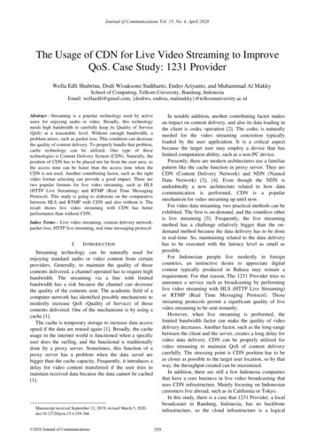
1-3System Block DiagramTPM2-Channel DDR4, 4 x DIMMsECC/ non ECC UDIMMSPIBIOSDDI 0HDMIDDI 1DisplayPortAudio JackAMD Socket AM4ALC897LPC2 x USB3.04 x USB2.0PCIe x16PCIe x1PCIe3.0 x4PCIe x16PCIe3.0 x2 / SATAIIIUSB2.0 x4M.2 SSDUSB3.0 x22 x USB3.0AMD B550Chipset(front)2 x 1GbE LANM.2 SSDPCIe4.0 x16PCIe3.0 x1PCIe4.0 x4USB3.0 x2Ryzen 5000 & 3000Series ProcessorsPCIe4.0 x4RTL8118PCIe3.0 x1RTL8111EPVPCIe3.0 x1PCIe3.0 x1M.2 WiFi2-bay 3.5" SATASATAIII x4LPCSIOCOM80HHardware Installation- 14 -
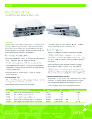
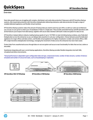
Chapter 22-1System AppearanceFront View51No.Description23674No. Description1.USB 3.2 Ports5.Power Button2.The function of 1394 Port is disabled6.Hard Drives Status LED3.Line Out Port7.Reset Button4.Mic In PortSystem Appearance- 15 -
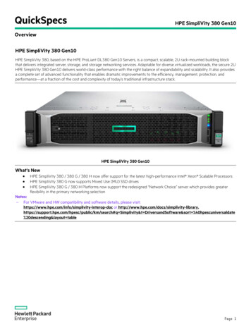
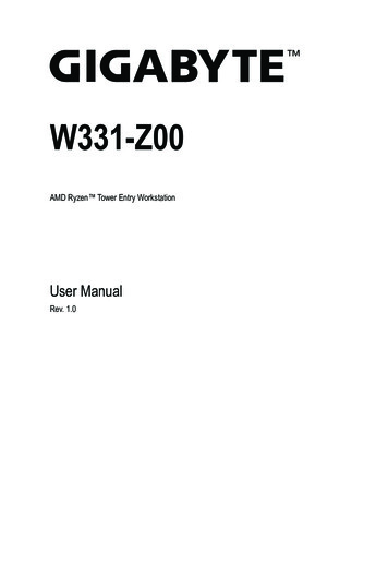
2-2Rear View123456871011912No.No. DescriptionDescription1.Power Supply Module Cord Socket7.GbE LAN Port #12.Display Port8.USB 2.0 Port x 43.Antenna Ports9.Line In Port (Blue)4.HDMI 2.1 Port10.Line Out Port (Green)5USB 3.2 Type A Port x 211.Mic In Port (Pink)6.GbE LAN Port #212.PCIe Card BayThe HDMI port is HDCP 2.3 compliant and supports Dolby TrueHD and DTS HD Master Audio formats.It also supports up to 192KHz/24bit 7.1-channel LPCM audio output. You can use this port to connectyour HDMI-supported monitor. The maximum supported resolution is 4096x2160@60Hz, but the actualresolutions supported are dependent on the monitor being used.System Appearance- 16 -
2-3Rear Panel System LAN LEDs1No.1.2.Name1GbE SpeedLED1GbE Link /Activity LED212ColorStatusYellowOn1 Gbps data rateGreenOn100 Mbps data rateN/AOff10 Mbps data rateOnLink between system and network or no accessGreenN/ABlinkOffDescriptionData transmission or reception is occurring.No data transmission or reception is occurring.System Appearance- 17 -
Chapter 3System Hardware InstallationPre-installation InstructionsComputer components and electronic circuit boards can be damaged by electrostatic discharge.Working on computers that are still connected to a power supply can be extremelydangerous. Follow the simple guidelines below to avoid damage to your computer or injury toyourself. Always disconnect the computer from the power outlet whenever you are working inside thecomputer case. If possible, wear a grounded wrist strap when you are working inside the computer case.Alternatively, discharge any static electricity by touching the bare metal system of the computercase, or the bare metal body of any other grounded appliance. Hold electronic circuit boards by the edges only. Do not touch the components on the boardunless it is necessary to do so. Do not flex or stress the circuit board. Leave all components inside the static-proof packaging until you are ready to use the componentfor the installation.System Hardware Installation- 18 -
3-1Removing and Installing the Chassis CoverBefore you remove or install the chassis cover Make sure the system is not turned on or connected to AC power.Follow these instructions to remove/install the chassis cover:1.2.3.Remove the screw securing the chassis cover.Slide the cover towards the rear of the system and then remove the cover in the direction indicatedby the arrow.Follow steps 1-2 in reverse order to re-install the top cover121System Hardware Installation- 19 -
3-2Installing the CPURead the following guidelines before you begin to install the CPU: Make sure that the motherboard supports the CPU. Always turn off the computer and unplug the power cord from the power outlet before installingthe CPU to prevent hardware damage. Unplug all cables from the power outlets. Disconnect all telecommunication cables from their ports. Place the system unit on a flat and stable surface. Open the system according to the instructions.WARNING!Failure to properly turn off the server before you start installing components may cause seriousdamage. Do not attempt the procedures described in the following sections unless you are aqualified service technician.Follow these instructions to Install the CPU:1.2.3.Lift up the CPU socket locking lever.Align the CPU pin one (triangle marking) with the pin one corner of the CPU socket. Install the CPUonto the socket.Ensure the CPU is positioned into its socket and secure the CPU socket lever.123System Hardware Installation- 20 -
3-3Installing the MemoryRead the following guidelines before you begin to install the memory: Make sure that the motherboard supports the memory. It is recommended that memory of thesame capacity, brand, speed, and chips be used. Always turn off the computer and unplug the power cord from the power outlet before installingthe memory to prevent hardware damage. Memory modules have a foolproof design. A memory module can be installed in only onedirection. If you are unable to insert the memory, switch the direction.3-3-1 Dual Channel Memory ConfigurationThis motherboard provides 4 DDR4 memory slots and supports Dual Channel Technology. After the memoryis installed, the BIOS will automatically detect the specifications and capacity of the memory.CPUDIMM4 A1DIMM4 A2DIMM4 B1DIMM4 B2System Hardware Installation- 21 -
3-3-2 Installing the MemoryBefore installing a memory module, make sure to turn off the computer and unplug the powercord from the power outlet to prevent damage to the memory module.Be sure to install DDR4 DIMMs on this motherboard.Follow these instructions to install the Memory:1.2.3.Insert the DIMM memory module vertically into the DIMM slot, and push it down.Close the plastic clip at both edges of the DIMM slots to lock the DIMM module.Reverse the installation steps when you want to remove the DIMM module.212Memory TypeDDR4Voltage (V)1.2VConnectorUDIMMSpeed (MT/s)29332666Channels1,2DIMM Per Channel1,2DIMM Capacity (GB)2,4,8,16,32Note: DIMM must be populated in sequential alphabetic order, starting withDIMM2 (DDR4 A2).When only one DIMM is used, it must be populated in memory slotDIMM2 (DDR4 B2).System Hardware Installation- 22 -
3-4Installing the PCI Expansion Card Voltages can be present within the server whenever an AC power source is connected. Thisvoltage is present even when the main power switch is in the off position. Ensure that thesystem is powered-down and all power sources have been disconnected from the server prior toinstalling a PCIe card. Failure to observe these warnings could result in personal injury or damage to equipment.Follow these instructions to install the PCI Expansion card:1.Use a screw driver to push the slot cover.2.Remove the slot cover from the PCIe bracket.3.Align the PCIe card onto the slot and push in the direction of the arrow until the PCIe card sits in thePCIe card connector.4.Secure the PCIe card with the screw.5.Reverse the previous steps to remove the PCIe card.2413System Hardware Installation- 23 -
3-5Installing the Hard Disk DriveRead the following guidelines before you begin to install the hard disk drive: Take note of the drive tray orientation before sliding it out. The tray will not fit back into the bay if inserted incorrectly. Make sure that the hard disk drive is connected to the hard disk drive connector on thebackplane.Follow these instructions to install a 3.5" hard disk drive:1.2.3.4.5.6.7.Loosen the thumbscrew securing the HDD cage.Press down the latch and pull out the HDD cage at the same time.Open the latches on the side of HDD cage.Slide the hard disk drive into the HDD cage.Push inward to make sure the HDD latches are in a locked position.Reinstall the HDD cage into the chassis.Tighten the thumbnail screw to secure the HDD cage in place. Finally, use a screw driver to securethe screw firmly.212356746System Hardware Installation- 24 -
3-6Installing and Removing the M.2 SSD ModuleFollow the steps below to install an optional M.2 SSD module on your motherboard.Step1. Insert the M.2 SSD module into the slot.Step2. Secure it with the screw, tightening as necessary to fasten the M.2 SSD module in place.23-71Installing and Removing the M.2 WiFi ModuleFollow the steps below to install a M.2 WiFi module on your motherboard.Step1. Carefully Insert the M.2 WiFi module into the slot.Step2. Secure it with the screw, tightening as necessary to fasten the M.2 WiFi module in place.System Hardware Installation- 25 -
3-8Peripheral Devices Connection12System Hardware Installation- 26 -
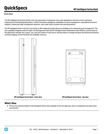
Chapter 44-1Motherboard ComponentsMotherboard Components12345626252120222472319CPU181516178DIMM4 A114DIMM4 A2DIMM4 B113DIMM4 B21012119Motherboard Components- 27 -
criptionAudio ConnectorsGbE LAN Port #1 (Top)/USB 2.0 Ports (Bottom)GbE LAN Port #2 (Top)/USB 2.0 Ports (Bottom)USB 3.2 Ports (Type A)HDMI 2.1 PortDisplay Port2x4 Pin 12V Power ConnectorCPU Fan Connector2x12 Pin Main Power ConnectorBattery SocketSATA III 6Gb/s Connector #0/#1SATA III 6Gb/s Connector #2/#3System Fan Connector #2Front Panel HeaderFront Panel USB 3.2 ConnectorM.2 Slot (SATA/PCIe Gen3 x2, Support NGFF-2280)M.2 Slot (PCIe Gen4 x4, Support NGFF-2280)Front Panel USB 2.0 ConnectorSerial Port Cable HeaderPCIe x16 Slot (Gen3 x4)PCIe x1 Slot (Gen3 x1)PCIe x16 Slot (Gen4 x16)M.2 Slot (WiFi/BT module, Support NGFF-2230)System Fan Connector #1System Fan Connector #3Front Audio HeaderMotherboard Components- 28 -
4-2Jumper SettingClear CMOSCLR CMOSNormal Opera on (Default)Clear CMOS dataMotherboard Components- 29 -
Chapter 5BIOS SetupBIOS (Basic Input and Output System) records hardware parameters of the system in the EFI on themotherboard. Its major functions include conducting the Power-On Self-Test (POST) during system startup,saving system parameters, loading the operating system etc. The BIOS includes a BIOS Setup program thatallows the user to modify basic system configuration settings or to activate certain system features. When thepower is turned off, the battery on the motherboard supplies the necessary power to the CMOS to keep theconfiguration values in the CMOS.To access the BIOS Setup program, press the DEL key during the POST when the power is turned on. BIOS flashing is potentially risky, if you do not encounter any problems when using the currentBIOS version, it is recommended that you don't flash the BIOS. To
The motherboard/system contain numerous delicate electronic circuits and components which can become damaged as a result of electrostatic discharge (ESD). Prior to installation, carefully read the user manual and follow these procedures: Prior to installation, do not remove or break motherboard S/N (Serial Number) sticker or