Transcription
If you are not hearing music, please check your speakersRadon Control Techniques in NewColorado HomesSponsored by:The Colorado Department of PublicHealth and EnvironmentPresented by: Doug KladderCenter for Environmental Research andTechnology, Inc.If you are not hearing music, please check your speakersMarch 2011CERTI Sponsored by the Colorado Department of Public Health and EnvironmentRadonChrystine KelleyEnvironmental Protection Specialist Colorado Department of Public Health &EnvironmentRadon Program Manager4300 Cherry Creek Dr S HMWMD-B2Denver, CO 80246Email: Chrys.Kelley@dphe.state.co.usRadon Hotline: 1-800-846-3986Radon website: d by:Doug KladderCenter for Environmental Research and Technology, Inc.1032 N. Wahsatch Ave.Colorado Springs, CO 80903phone: 719-477-1714email: DKladder@Certi.us Copyrighted by the Center for Environmental Research and Technology Inc - Revised March 20111
Mechanics Schedule 10:00 AM to 11:00 AM Format: Slides and live audio to attendees Typed questions from attendees Educational site Additional resources EvaluationNote: This conference will NOT be recordedCERTI Please sign in a few minutes early to insure your computer speakers areworking properly.Be sure to return to the educational website for additional information andalso complete a quick course evaluation. Copyrighted by the Center for Environmental Research and Technology Inc - Revised March 20112
Asking QuestionsBoulder: What are the drawbacksof connecting to a sump?Primary Site: One could loseconsiderable air from house whenlid is removed.Longmont: What about radon inwater?1. Type question in box3. Click Enter button2. Select To EveryoneCERTI Questions will be answered during the latter portion of the program. Copyrighted by the Center for Environmental Research and Technology Inc - Revised March 20113
Additional Resources and ResponsesAvailable on Web SiteResources Videos Follow-upAnswers Discussion Retain logininformation Evaluation CERTI You will be able to access this site for at least 2 months after the web cast Copyrighted by the Center for Environmental Research and Technology Inc - Revised March 20114
PurposeInitiate discussion on radon controltechniques that work well for ColoradoCost effective Reliable Protects Consumer Protects Builder CERTI Copyrighted by the Center for Environmental Research and Technology Inc - Revised March 20115
Framing the Issue1. Radon is a Group A Carcinogen,2. Radon comes from granite geologies (Rockies),3. Over 50% of homes in Colorado have elevatedradon levels,4. Appendix F of the IRC provides prescriptiveapproach for reduction,5. More and more Colorado communities eitherhave or are considering adoption of Appendix F.What makes sense for Colorado?CERTI Copyrighted by the Center for Environmental Research and Technology Inc - Revised March 20116
Appendix F of the International Residential CodeRadon Systems in New Homes Required in:Counties: Cities:ArchuletaBoulderGilpinHinsdaleHuerfanoLas AnimasLogan AspenFort CollinsGoldenSterlingAs of February 2011 - Source: CDPHECERTI Copyrighted by the Center for Environmental Research and Technology Inc - Revised March 20117
What Is Radon? Radon Radon is a gas.It is naturally occurring.It is inert and cannot beseen or smelled.It enters buildings fromthe soil beneath them.RadiumUraniumCERTI Radon is a gas that is created in the soils where uranium and radium are found.These elements can be found everywhere in the world, therefore any building hasthe potential for elevated levels of radon. The more uranium found in the soil, thehigher the potential for elevated radon levels within a building constructed abovethis soil. The question is not, “Is there radon?” but rather, “How much radon isthere?”Radon comes from natural deposits of uranium in the soil. It is not because of amanmade landfill or other suspicious sources.Uranium breaks down to radium, which in turn decays into radon gas. Radon isan inert gas, which means that it does not react or combine with the elements inthe ground. Because of this, radon gas can move up through the soil into theatmosphere, where it is easily diluted and presents little concern. However, whenit enters a building constructed on top of this soil, it can build up and become ahealth concern.You cannot see or smell radon. There is no way that your body can sense thepresence of radon, yet, it can have a detrimental effect on inhabitants byincreasing their likelihood of developing lung cancer. Copyrighted by the Center for Environmental Research and Technology Inc - Revised March 20118
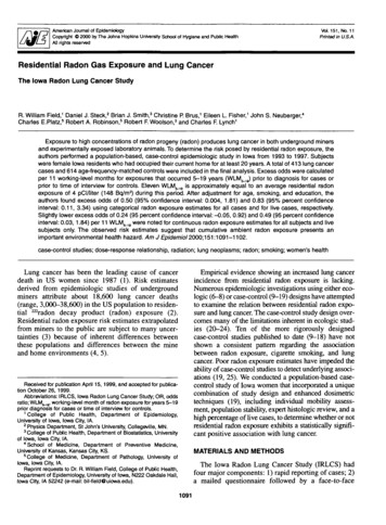
EPA & Surgeon General RecommendThat People Not Have ExposuresAbove 4 pCi/L On A Long-Term BasisCERTI The EPA has recommended a guidance level of 4.0 pCi/L since the mid 1980s where it wasfirst established during uranium mill tailing clean up on the western slope of Colorado.This guidance has remained in place ever since and applied to homes that have naturalsources of radon, rather than just uranium mill tailing contamination. This reinforcement hasbeen the result of numerous residential studies throughout the U.S, Europe and Asia thatsuggest that there still is significant health risks from exposures below 4.0 pCi/L.The 4.0 pCi/L guidance is not a “safe level” but rather was an economical guidance selectedbased upon technology utilized in the early 1980s. The table below shows a chronology ofseveral milestones in the study of this issue, including the recent recommendations by theWHO for a reference level less than the current U.S. EPA recommendation.1945 First study linking radon to lung cancer (miners)1984 Residential Exposure Headlines (Pennsylvania)1986 EPA Issues 4 pCi/L recommendation1990's Relocation Firms begin requiring homes 4.0 pCi/L1999 NAS confirms risk (BEIR VI)2000 Appendix F of IRC Passive Radon Control Systems2003 Science Advisory Board Reassessment confirms risk and 4.0 pCi/L2005 Surgeon General Advisory on Radon Exposure2005 Pooled Residential Studies Confirm Risk in Homes2006 ASTM Standard for New Homes2007 Canada drops radon guidance to 5.4 pCi/L2009 World Health Org finalizes 3 yr. study - guidance: 2.7 pCi/L2009 Health Physics Society confirms risk and supports 4 pCi/L Copyrighted by the Center for Environmental Research and Technology Inc - Revised March 20119
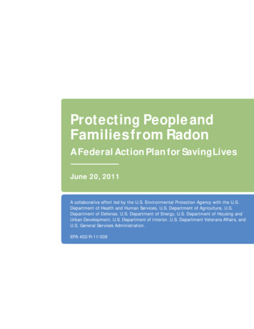
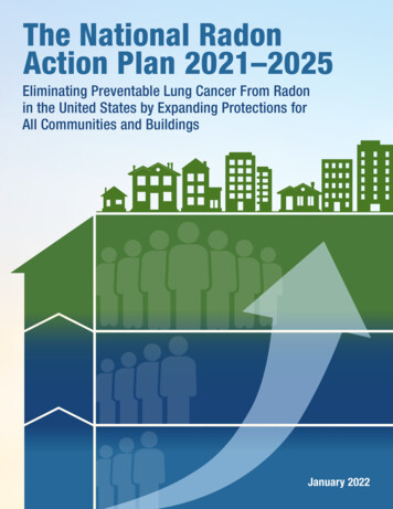
U.S. EPA Map of Radon Zones? Based on geology andradon surveysExpected closedbuilding radon (pCi/L) Zone 1 4.0 Zone 2 2.0 - 4.0 Zone 3 2.0This map was developed as the basis for radon control techniques in new construction.CERTI Radon is not an isolated concern for this state. Radon has been foundeverywhere in this country and all over the world. The question pertains towhether or not radon is higher than the recommended 4.0 pCi/L.Surveys began in the mid 1980’s. The map above shows the potential for indoorradon concentrations by county, based upon previous surveys and geology. Thismap, or others like it, should not be used as a substitute for an actual radon test.The only way to determine radon concentrations in a building is by testing thatstructure.This map can be a useful tool in dealing with a buyer who is reluctant to buy ahome in an area thought to have a high incidence of radon levels above 4.0 pCi/L.There are a lot of areas with radon concerns. A buyer may even be moving froman area with elevated radon and not even known it.Always keep in mind that radon can easily be measured for and corrected. Itshould not be a deal buster! Copyrighted by the Center for Environmental Research and Technology Inc - Revised March 201110
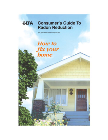
Percentage of Elevated Homes in AttendeeCounties – Compared to U.S. Average70%60%50%40%30%U.S. tEagleEl PasoDeltaChaffeeBoulder0%Archuleta10%Adams% Homes above 4.0 pCi/L80%Source: Air Check, March 6, 2011 www.radon.comCERTI Copyrighted by the Center for Environmental Research and Technology Inc - Revised March 201111
So How Do WeFix IT?CERTI Copyrighted by the Center for Environmental Research and Technology Inc - Revised March 201112
How Is Radon Drawn Into A Building? Vacuum Exhaust systems Thermal stack effects80Radon pCi/L604020Vacuum (pa.)01234DaysCERTI Buildings are typically at a lower pressure than the surrounding air and soil. This causesradon and other soil gases to be drawn into the building.There are several reasons this occurs. One cause is the effect that exhaust fans have whenremoving air from a building. When air is exhausted, outside air enters the building toreplace it. Much of this replacement air comes in from the underlying soil.When interior temperatures are higher than outside temperatures, thermal effects occurinside of the building. Just as warm air causes a balloon to rise because the surrounding airis cool, warm air rises within a building and is displaced by cold, dense outside air. Some ofthe outside air, which is displacing and replacing the interior air, comes from the soil.Whenever air enters a building from underneath, radon will most likely come in as well ifradon is present in the underlying soil.The forces that draw radon into a structure vary, which in turn effects the entry rate of radon.Measurement devices that average radon levels over long periods of time provide a betterindication of the amount of exposure to radon. Copyrighted by the Center for Environmental Research and Technology Inc - Revised March 201113
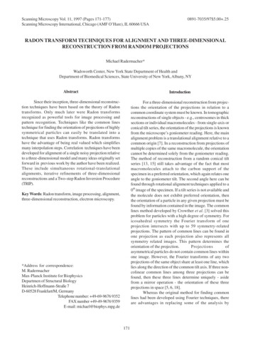
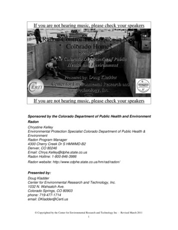
New Homes Can Be Built With Radon Control SystemsFANPassiveActivewith Fan 50% toReductionReduction 2.0 or lowerHIGH LOWCERTI The figure above illustrates the basic concept of radon control systems installedduring the construction of a home. The key to these systems is to insure that soilgases and radon can move easily from underneath the building toward a singleriser pipe that is routed up through the home and exits through the roof. In the caseof a concrete floor in a basement or slab-on-grade home, this could be a 4 inchlayer of 3/4 inch washed gravel placed prior to pouring the floor. Other options area gas collection system consisting of a loop of buried perforated pipe inside thefooting or matting laid on the sub-grade dirt under the slab. In any case, thesemechanisms will allow the soil gases to be easily collected.The pipe riser should be routed through the interior of the building to allow the riserto be warmed, thus creating a natural stack effect. When this riser is combined withthe easy gas collecting capabilities of the system installed beneath the slab, it candraw significant amounts of radon from beneath the home. The performance of thisnatural convection system is enhanced by sealing openings in the slab and walls sothe air drawn up through the system comes from beneath the building rather thanfrom within the building. These passive systems are further enhanced by routingthe pipe through the warmest spaces in the home (like the chase where the furnaceand hot water flues are located.) The radon vent should not be connected to anycombustion flues or soil vents. This passive approach is not an option with existinghomes because of the need for the permeable system that is specially designedand installed beneath the slab only during construction. Allowance is always madefor future installation of a fan should testing indicate that this is necessary. Copyrighted by the Center for Environmental Research and Technology Inc - Revised March 201114
Make Provisions To Allow ForSystem ActivationActivePassiveCERTI In many cases, passive relief from beneath the slab or the plastic sheeting onthe crawl space floor is sufficient to reduce radon to concentrations suitable tothe homeowner. However, if the homeowner should desire further reductions,provisions should be made to allow them to do so.This would consist of allowing a sufficient length of pipe pipe in a locationsuitable for the installation of a fan. Additionally, provisions should be made forpower, as well as a system performance indicator. Copyrighted by the Center for Environmental Research and Technology Inc - Revised March 201115
Treating SlabsBasementSlab-on-gradeDesigned to Make Sub-Grade Porous and aMeans to Collect Radon laden Soil GasCERTI If the slab is in direct contact with soil, the collection of radon laden soilgas is improved by making the sub-grade more porous such that thelateral movement of soil gases is improved.Appendix F:AF103.2 Subfloor preparation. A layer of gas-permeable material shall beplaced under all concrete slabs and other floor systems that directly contactthe ground and are within the walls of the living spaces of the building, tofacilitate future installation of a sub-slab depressurization system, if needed.The gas-permeable layer shall consist of one of the following:A uniform layer of clean aggregate, a minimum of 4 inches (102mm) thick. Theaggregate shall consist of material that will pass through a 2-inch (51 mm)sieve and be retained by a 1/4-inch (6.4 mm) sieve.A uniform layer of sand (native or fill), a minimum of 4 inches (102 mm) thick,overlain by a layer or strips of geotextile drainage matting designed to allowthe lateral flow of soil gases.Other materials, systems or floor designs with demonstrated capability to permitdepressurization across the entire sub-floor area.The alternate methods were expanded in Fort Collins adaptation Copyrighted by the Center for Environmental Research and Technology Inc - Revised March 201116
Improving Soil Gas CollectionDuring Construction Of Slabs1. Four inch layer of clean aggregate beneath slab. When gravel is incorporated for drainage or isinexpensive.2. Loop of perforated pipe beneath slab. When existing soils are permeable.3. Interconnected strips of drainage mat beneathand around interior perimeter of slab. When soil is well compacted.CERTI The concept for dealing with slabs is to provide a means for gases in the soil,such as radon, to move freely through the soil to a collection point. It has beenshown that this can occur by at least three proven methods. The choice of whichmethod is to be used is purely a matter of economics. It would appear, at thepresent time that all three are equivalent.If gravel is inexpensive, or placing gravel beneath a slab is a normal feature ofconstruction, then gravel option would be the most cost effective.If native soils are permeable enough to allow for water drainage then the poorerporosity of uncleaned fills can be overcome by installing a loop of perforated pipein the subgrade to facilitate collection.The perforated pipe may be replaced by lengths of 1 inch tall matting laid betweenthe subgrade and the bottom of the slab and connected to form a rectilinear looparound the interior of the foundation perimeter. The choice of the mat over theperforated pipe is made upon the degree of difficulty and cost in trenching in aperforated pipe, compared to laying a strip of material on top of the prepared subgrade immediately prior to pouring the slab. Copyrighted by the Center for Environmental Research and Technology Inc - Revised March 201117
Option 1: Aggregate Option 4 inches of clean aggregate Between 1/4 inch and 22-inch in size CaulkSoil gas retarder Minimum 6 mil polySlabFootingAggregateFill or native soils6-mil sheeting4-inches Overlapped and extended to edges Punctures and tears to be sealed Slab joints to be caulked andsealed.Note: Fort Collins opted to: Eliminate sealing of plastic with well sealed slab Allow pea gravelCERTI AF103.2 Option 1:A uniform layer of clean aggregate, a minimum of 4 inches (102 mm) thick. Theaggregate shall consist of material that will pass through a 2-inch (51 mm) sieveand be retained by a 1/4 -inch (6.4 mm) sieve. A uniform layer of washed gravelwill provide a path for radon to flow through provided it is not obstructed byintermediate footings or concrete that sinks into the voids within the gravel layer.Note: if smaller aggregate is used than specified above, its ability to collect soilgas is to be enhanced with one of the other options (perforated pipe loop ordrainage mat.Gravel is often a normal design feature of a building for the collection of water. Ifthis is the case, then little additional cost is involved by selecting this method.Fort Collins Adaptation:The Fort Collins Code does not require a sealed polyethylene sheeting beneaththe concrete. Rather the gas resistant seal is accomplished by caulking andsealing floor-to-wall joints, control joints and plumbing penetrations. This doesnot prevent the use of moisture barriers under slabs, but rather that specialprecautions for sealing plastic for radon control methods is not required. Copyrighted by the Center for Environmental Research and Technology Inc - Revised March 201118
Soil Gas RetarderCan beexpensive Labor intensiveto seal May requirespecial additivesfor concrete CERTI In some publications, it is suggested the membrane under the slab be sealed at allpenetrations, seams and around sumps (See ASTM 1465).This can be very labor intensive and can also cause cracking issues with theconcrete if it cannot properly de-water.In considering this in Fort Collins, it was decided that a vapor barrier could go downas is normally done, but the top of the slab be well caulked. Note it is easier for aninspector to see caulk in a basement before it is finished than to inspect the plasticmembrane before the concrete arrives. Copyrighted by the Center for Environmental Research and Technology Inc - Revised March 201119
Aggregate Option:Allowing for Lateral Air FlowPost and BeamFoundation with Grade BeamRiserRiserSleeves Minimum of two grade beampenetrations. Minimum of 12 sq. inches ofopening per 10 ft. of grade beam.CERTI Often a grade beam or intermediate footing is installed beneath a slab to provide support of a loadbearing wall. These grade beams can present a barrier to the lateral flow of air beneath the slab tothe system collection point. This can be avoided by using post and beam construction where teleposts that support overhead beams are set on pads rather than continuous footings.If a continuous grade beam is used then a means to allow the air to flow through the grade beam mustbe provided. This is typically accomplished by inserting at least two 4 inch pipe sleeves between theform boards or trench and pouring the grade beam over them. The spacing of these pipes should beat opposite ends of the grade beam with a spacing of one every 10 feet, with a minimum of twoinstalled. The pipe can be 4 inch schedule 40 PVC or 4 inch corrugated ADS pipe. Be sure to tapethe ends so concrete does not enter the ends of the pipe while pouring the footing. Remove tape afterforms are removed.Appendix F does not specifically address this approach, but rather specifies a separate vent pipe foreach area as follows:AF103.6.2 Multiple vent pipes. In buildings where interior footings or other barriers separate thesub-slab aggregate or other gas-permeable material, each area shall be fitted with an individual ventpipe. Vent pipes shall connect to a single vent that terminates above the roof or each individual ventpipe shall terminate separately above the roof.Other code jurisdictions have used the following language to allow for more cost-effective sub-slabcross-overs:In buildings where interior footings or other barriers separate sub-grade areas, penetrations throughthe interior footing or barrier equal to a minimum of 12 square inches (0.094 m2) per 10 feet (3.048 m)of barrier length shall be provided. A minimum of two penetrations shall be provided per separationand be evenly spaced along the separation. Copyrighted by the Center for Environmental Research and Technology Inc - Revised March 201120
Aggregate Option:Connecting Gravel to Vent PipeSch. 40 PVC PipePVC Pipe CouplingSlabSlab“Tee” MinimumRequirementSch. 40 PVC PipePortion of vent pipe to beconnected to sub-gradebefore concrete pour. Minimum 3-inch “Tee” orPVC Pipe Couplingequivalent Means to keep fitting fromfilling with gravel ispreferred.SlabReducesAir BlockageSch. 40 PVC Pipe PVC Pipe CouplingSlabComplies with codeand reducespotential blockageShort length or perforatedpipe beneath slab. “Tee” should be same sizeas riserCERTI AF103.5.1 Vent pipe riser. A minimum 3-inch-diameter (76 mm) ABS, PVC orequivalent gas-tight pipe shall be embedded vertically into the sub-slab aggregateor other permeable material before the slab is cast. A “T” fitting or equivalentmethod shall be used to ensure that the pipe opening remains within the sub-slabpermeable material.It does no good to go to the trouble of placing gravel beneath the slab and insuringgood air flow, if the pipe is stuck directly into the gravel. You need to allow for easyentry of the air into the pipe. In the case of the gravel alternative this is mostcommonly accomplished by using 4 inch corrugated and perforated pipe (drain fieldpipe) at least 10 feet in length. This can be accomplished with a PVC Tee (asshown) or a PVC 90 degree elbow with a single length of perforated pipe securedinto the throat of the 90.In the case of large buildings such as schools or apartment buildings, largerectangular metal pits have been constructed and located in the gravel beneath theslab. It is constructed from angle iron which supports a solid metal decking uponwhich the slab rests. Around the perimeter of the box is expanded metal that facesthe sub-slab aggregate and allows the radon to enter the interior of the box. Thevent pipe is connected directly to the box. (See Radon prevention in the Design andConstruction of Schools and Other Large Buildings, Third Printing with Addendum,June 1994, EPA/625/R-92/016) Copyrighted by the Center for Environmental Research and Technology Inc - Revised March 201121
Option 2: Perforated PipePassive Vent Riser Continuous loop ofperforated pipe. Roughly 12 inches fromwalls. Suggest 2 foot clearancefrom sub-grade drainagelines if present Flexible or rigid pipe Wrapped with filter cloth.Perforated PipeFlexible andperforated pipecan be purchasedwith “sock”sock” on.CERTI In some regions of the country native soils are permeable enough not to require theimportation of gravel for water drainage. In other areas, the importation of gravel is veryexpensive. In the case where gravel is not already being used, or is expensive, it may bemore cost-effective to use the native fills beneath the slab and improve soil gas movementby laying in a loop of perforated pipe. This works well because the soil gases need onlymove to the loop rather than all the way across the slab (as would be the case if a singlecollection point was used.)The following addendum was added to the Fort Collins Code to allow for the use ofthis approach:A foundation drain pipe system installed under concrete floor slab areas less than 2,000square feet (186 m2), consisting of a continuous loop of minimum 3-inch (76 mm.) diameterperforated pipe shall be laid in the sub-grade with the top of pipe located 1 inch (25.4 mm)below the concrete slab. The pipe may be rigid or flexible but shall have perforations fullyaround the circumference with a free air space equal to 1.83 square inches per square foot(127 cm2/ m2) of exterior pipe surface area. Such pipe shall be wrapped with approvedfilter material to prevent blocking of pipe perforations. The pipe loop shall be located insideof the exterior perimeter foundation walls not more than 12 inches (305 mm) from theperimeter foundation walls. In buildings where interior footings or other barriers separatethe sub-grade area, the loop of pipe shall penetrate, or pass beneath such interior footingsor barriers.Note: The perforated pipe should be a “nominal” 12-inches off the walls. It can veer awayfrom wall to distances greater than 12–inches to avoid plumbing penetrations, etc., butshould return to the “nominal” 12-inches after avoiding interference. Copyrighted by the Center for Environmental Research and Technology Inc - Revised March 201122
Trench Option CVCInstead of gravel throughout Gravel and perforated pipe in trench Loop design CERTI Copyrighted by the Center for Environmental Research and Technology Inc - Revised March 201123
Sub-Grade Pipe Size and Loops4”3”20003”3”60004000Footprint (S.F.)4”4”LoopsDiam.Up to 2,00013"2,000 to 4,00014"4,000 to 6,00023"8,00024"orLoopsDiam23"Loops should be interinter-connected8000CERTI The reason for laying it out in a loop is to allow for the soil gas to enter the verticalvent pipe from two sides. Another reason for the loop is that if it is crushed at onepoint during construction the soil gas will still be drawn to the vent pipe.Fort Collins Verbiage:AF103.2 Option 2:A foundation drain pipe system installed under concrete floor slab areas less than2,000 square feet (186 m2), consisting of a continuous loop of minimum 3-inch (76mm.) diameter perforated pipe shall be laid in the sub-grade with the top of pipelocated1inch(25.4mm)belowtheconcreteslab For slab areas greater than2,000 square feet (186 m2) but less than 4,000 square feet (372 m2), the precedingconfiguration may be used provided a minimum of 4-inch diameter (102 mm) pipe isinstalled. Slabs in excess of 4,000 square feet (372 m2) shall have under themseparate loops for every additional 2,000 square feet (186 m2) of slab area when 3inch (76 mm) diameter pipe is used; or, slabs may have separate loops provided foreach additional increment in area between 2,000 square feet (186 m2) and 4,000square feet (372 m2) when 4-inch (102 mm) diameter pipe is used. Copyrighted by the Center for Environmental Research and Technology Inc - Revised March 201124
Perforated Pipe Option: Cross-OversRiserGarage Grade BeamMake provisions for pipe topenetrate obstructions. Short lengths laid in trenchesPipe Loop Tape ends to keep clear ofdebris. Attach to main loopafter grade beam finished Pipe sleeves in intermediateImportant:When passing under grade beamsmake sure that perforations of pipeallow drainagefootings. Pass perforated pipe through.CERTI The riser can be anywhere on loop(s) of perforated pipe that is convenientfor routing vent pipe up through structure.Perforated and corrugated ADS pipe is flexible which makes it is easy to laydown in a trench. The perforations also allow for good soil gas collection.Be sure the pipe is covered by at least 1 inch of fill to keep concrete fromfilling perforations.Where perforated pipe is to pass through or under grade beams/intermediatefootings:If pipe is beneath grade beam, water must be able to drain from inside ofpipe.Put short-lengths through trench before pouring and later connect stubs tomain system (be sure debris cannot enter pipe, while unattached.Or install pipe sleeves through which pipe can be passed through afterintermediate foundation is set. Copyrighted by the Center for Environmental Research and Technology Inc - Revised March 201125
Perforated Pipe Option: RiserSch. 40 PVC PipePVC Pipe CouplingSlabCorrugated, PerforatedPolyethylene pipe8” stub of 4” PVC PipeTee and perforated pipe same diameter as vent pipe.CERTI Locating where you want the riser to come up through the slab is a functionof where you want to route the piping up through the house. Typicallyhaving it come up in the furnace (utility) room is preferred because it is anout-of-the way place and you can run the vent piping up through the fluechase. Furthermore having the pipe enter warmer areas, such as the furnaceroom will enhance the stack-effect and reduce the need for an active system.Where the riser connects to the sub-slab loop doesn’t make any differenceprovided that you have made a complete loop with the perforated pipe.The corrugated and perforated pipe should be connected to short pipe stubsand connected to opposite legs of a 4 inch PVC Tee. When three inchcorrugated pipe is used, the corrugated pipe can be inserted into the pipestubs and secured with sheet metal screws. When 4 inch corrugated pipe isused, 4 inch by 4 inch rubber couplings can be used to connect theperforated pipe to the solid PVC pipe stubs. Copyrighted by the Center for Environmental Research and Technology Inc - Revised March 201126
Option 3: Mat OptionExploded Viewof MatCaulkMatFilter FabricMinimum 1 inch high & 12 inches wide. Lay mat directly on subgrade Pour concrete over mat CERTI In some regions of the country native soils are permeable enough not to require the importation ofgravel for water drainage. In other areas, the importation of gravel is very expensive. In the casewhere gravel is not already being used or is expensive it may be more cost-effective to use thenative fills beneath the slab but to improve air movement by laying in a rectilinear loop of soil gascollection mats. When it is easy to dig a trench and lay in corrugated pipe that option is typicallyused. Where sub-grade soils are compacted, the ground is frozen, or labor is expensive drainmats are often used.Drain mats consist of a plastic material that resembles an egg-crate. Wrapped around the “eggcrate” is a geotechnical filter fabric that allows for the passage of air but prevents the infiltration ofwet concrete. Because of this, the mat can be laid directly on top of the prepped sub-grade andthe concrete poured directly over it. It is a little more expensive than perforated pipe, but theinstallation is very fast.Note: a minimum of 3.5 inches of concrete must be maintainedAF103.2 Paragragh 2: A uniform layer of sand (native or fill), a minimum of 4 inches (102 mm) thick,overlain by a layer or strips of geotextile drainage matting designed to allow the lateral flow of soilgases.Fort Collins Addition:A foundation drain soil gas collection mat system installed under concrete floor slab areas of 2,000square feet (186 m2) or less, consis
Radon Control Techniques in New Colorado Homes Sponsored by: The Colorado Department of Public Health and Environment Presented by: Doug Kladder Center for Environmental Research and Technology, Inc. March 2011 . Colorado Springs, CO 80903 phone: 719-477-1714 email: DKladder@Certi.us