Transcription
ICTP-ITU-URSI School on Wireless Networking for DevelopmentThe Abdus Salam International Centre for Theoretical Physics ICTP, Trieste (Italy), 5 to 24 February 2007Basic Antenna TheoryRyszard StruzakNote: These are preliminary notes, intended only fordistribution among the participants. Beware of misprints!
Purpose to refresh basic physical conceptsneededto understand betterthe operation and design of microwaveantennasR Struzak2
Outline IntroductionReview of basic antenna typesRadiation pattern, gain, polarizationEquivalent circuit & radiation efficiencySmart antennasSome theorySummaryR Struzak3
QuizTransmitting antennasused to radiate RF energy, whereasreceiving antennasdesigned to capture RF energySomebody told that receiving antennas,radiate radio waves during the receptionIs it a true fact or a slip of the tongue?R Struzak4
It is true.R Struzak5
Intended & unintended radiators Intended antennas– To produce/ receive specified EMwaves: Radiocommunication antennas; Measuring antennas; EM sensors, probes; EM applicators (Industrial, Medical,Scientific)R Struzak6
Unintended antennas - active– EM waves radiated as an unintended sideeffect: Any conductor/ installation with varying electricalcurrent (e.g. electrical installation of vehicles) Any slot/ opening in the screen of a device/ cablecarrying RF currentR Struzak7
Unintended antennas - passive Any discontinuity in transmission medium(e.g. conducting structures/ installations)irradiated by EM waves– Stationary (e.g. antenna masts or power linewires);– Time-varying (e.g. windmill or helicopterpropellers);– Transient (e.g. aeroplanes, missiles)R Struzak8
Antenna functionSpace wave Transformation of a guided EMwave (in waveguide/ transmissionline ) into an EM wave freelypropagating in space (or viceversa)– Transformation from time-function intoRF wave ( vectorial field dependenton time and 3 space-dimensions)– The specific form and direction of thewave is defined by the antennastructure and the environmentGuided waveR Struzak9
Transmission line– Power transport medium – the transition ideallywithout power reflections (matching devices!) Radiator– Must radiate efficiently – must be of a sizecomparable with the half-wavelength Resonator– Unavoidable - for broadband applicationsresonances must be attenuatedR Struzak10
Monopole (dipole over plane)SharptransitionregionUniform wavetravelingalong the line Thin radiatorThick QBroadband If there is an inhomogeneity (obstacle, or sharp transition), reflections, higher fieldmodes and standing wave appear.With standing wave, the energy is stored in, and oscillates from electric energy tomagnetic one and back. This can be modeled as a resonating LC circuit withQ (energy stored per cycle) / (energy lost per cycle) Kraus p.2R Struzak11
Outline IntroductionReview of basic antenna typesRadiation pattern, gain, polarizationEquivalent circuit & radiation efficiencySmart antennasSome theorySummaryR Struzak12
Dipole antenna Java apllet on thin linear dipole antenna(length t/DipoleAnt-2.html Java applet on detailed analysis of tenna1/Antenna1-2.htmlR Struzak13
Dipole, Slot & INF antennas Slot antenna: a slot is cut from a large (relativeto the slot length) metal plate. The center conductor of the feeding coaxial cable isconnected to one side of the slot, and the outside conductorof the cable - to the other side of the slot.– The slot length is some (λ/2) for the slot antenna and(λ/4) long for the INF antenna. The INF and the slot antennas behave similarly. The slot antenna can be considered as a loaded version ofthe INF antenna. The load is a quarter-wavelength stub, i.e. anarrowband device. When the feed point is moved to the short-circuited end ofthe slot (or INF) antenna, the impedance decreases. When itis moved to the slot center (or open end of the INF antenna),the impedance increasesR Struzak14
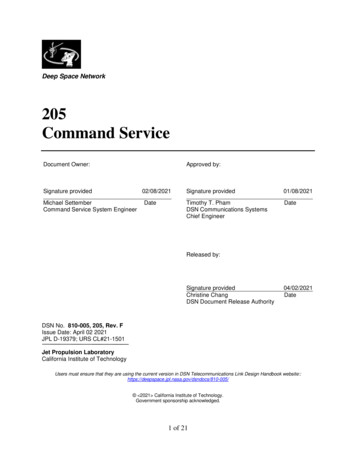
Antennas for laptop applicationsR StruzakSource: D. Liu et al.: Developing integrated antenna subsystems for laptop computers; IBM J. RES. & DEV. VOL. 47 NO. 2/3 MARCH/MAY 2003 p. 355-36715
Patch and slot antennasderived from printed-circuit andmicro-strip technologies Ceramic chip antennas aretypically helical or inverted-F(INF) antennas, or variations ofthese two types with highdielectric loading to reduce theantenna sizeSource: D. Liu et al.: Developing integrated antenna subsystems for laptopcomputers; IBM J. RES. & DEV. VOL. 47 NO. 2/3 MARCH/MAY 2003 p. 355-367R Struzak16
Patch and slot antennas are– Cheap and easy to fabricate and to mount– Suited for integration– Light and mechanically robust– Have low cross-polarization– Low-profile - widely used in antenna arrays– spacecrafts, satellites, missiles, cars and other mobileapplicationsR Struzak17
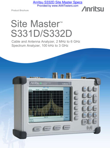
Aperture-antennaEM wavePowerabsorbed: P [watt]Effectiveaperture: A[m2]Power density:PFD [w/m2]A A*PFD Aperture antennasderived fromwaveguide technology(circular, rectangular) Can transfer highpower (magnetrons,klystrons) Above few GHz Will be explored inpractice during theschool R StruzakNote: The aperture concept is applicable also to wiredantennas. For instance, the max effective aperture oflinear λ/2 wavelength dipole antenna is λ2/818
Leaky-wave antennas Derived from millimeterwave guides (dielectricguides, microstrip lines,coplanar and slot lines). For frequencies 30 GHz,including infrared Subject of intensive study.– Note: Periodicaldiscontinuities near the endof the guide lead tosubstantial radiationleakage (radiation from thedielectric surface).Source: adapted from N GregorievaR Struzak19
Reflector antennas Reflectors are used to concentrate flux of EMenergy radiated/ received, or to change itsdirection Usually, they are parabolic (paraboloidal).– The first parabolic (cylinder) reflector antenna wasused by Heinrich Hertz in 1888. Large reflectors have high gain and directivity– Are not easy to fabricate– Are not mechanically robust– Typical applications: radio telescopes, satellitetelecommunications.Source: adapted from N GregorievaR Struzak20
Image Theory Antenna above perfectlyconducting plane surfaceTangential electrical fieldcomponent 0 – vertical components: thesame direction– horizontal components:opposite directions The field (above the ground)is the same as if the groundis replaced by an mirrorimage of the lR StruzakElliptical polarization:change of the rotation sense!21
Planar reflectorsd2d Uda-Yagi, Log-periodic antennas R StruzakIntended reflector antennaallows maintaining radio link innon-LOS conditions (avoidingpropagation obstacles)Unintended reflector antennascreate interference22
Exampledouble-layer printed Yagi antenna matching transformerNote: no galvanic contact with thedirectorSource: N GregorievaR Struzak23
Paraboloidal reflectorsFront feedOffset feedR StruzakCassegrain feed24
The largest radio telescopes Max Plank Institüt für Radioastronomieradio telescope, Effelsberg (Germany),100-m paraboloidal reflector The Green Bank Telescope (the NationalRadio Astronomy Observatory) –paraboloid of aperture 100 mSource: adapted from N GregorievaR Struzak25
The Arecibo Observatory AntennaSystemThe world’slargest singleradio y andIonosphereCenter (USA),Arecibo,Puerto RicoR Struzak26
The Arecibo Radio Telescope[Sky & TelescopeFeb 1997 p. 29]R Struzak27
Lens antennasLenses play a similar role to that of reflectors in reflector antennas:they collimate divergent energyOften preferred to reflectors at frequencies 100 GHz.Source: Kraus p.382, N GregorievaR Struzak28
Outline IntroductionReview of basic antenna typesRadiation pattern, gain, polarizationEquivalent circuit & radiation efficiencySmart antennasSome theorySummaryR Struzak29
Antenna characteristics of gain,beamwidth, efficiency, polarization, andimpedance are independent of theantenna’s use for either transmitting orreceiving. The properties we will discuss here applyto both cases.R Struzak30
Radiation pattern The radiation pattern of antenna is a representation(pictorial or mathematical) of the distribution of the powerout-flowing (radiated) from the antenna (in the case oftransmitting antenna), or inflowing (received) to theantenna (in the case of receiving antenna) as a functionof direction angles from the antenna Antenna radiation pattern (antenna pattern):– is defined for large distances from the antenna, where the spatial(angular) distribution of the radiated power does not depend on thedistance from the radiation source– is independent on the power flow direction: it is the same when theantenna is used to transmit and when it is used to receive radio waves– is usually different for different frequencies and different polarizationsof radio wave radiated/ receivedR Struzak31
Power pattern vs. Field patternAntennaunder testLargedistanceAuxiliaryantennaAUTPower- orfield-strength meterGeneratorTurntable The power pattern and the field patternsare inter-related for plane wave:P(θ, ϕ) (1/η)* E(θ, ϕ) 2 η* H(θ, ϕ) 2P powerE electrical field component vectorH magnetic field component vectorη 377 ohm (free-space, plane waveimpedance) The power pattern is themeasured (calculated)and plotted receivedpower: P(θ, ϕ) at aconstant (large) distancefrom the antenna The amplitude fieldpattern is the measured(calculated) and plottedelectric (magnetic) fieldintensity, E(θ, ϕ) or H(θ, ϕ) at a constant(large) distance from theantennaR Struzak32
Normalized pattern Usually, the pattern describes thenormalized field (power) values withrespect to the maximum value.– Note: The power pattern and the amplitudefield pattern are the same when computedand when plotted in dB.R Struzak33
Reference antenna (λ/2 dipole)Reference antenna (λ/2 dipole)R Struzak34
R Struzak35
‘Biquad’Biquad antennaR Struzak36
‘Cantenna’CantennaR Struzak37
3-D pattern Antenna radiationpattern is3-dimensional The 3-D plot of antennapattern assumes bothangles θ and ϕ varying,which is difficult toproduce and to interpret3-D patternSource: NK NikolovaR Struzak38
2-D pattern Usually the antennapattern is presented as a2-D plot, with only one ofthe direction angles, θ orϕ varies It is an intersection of the3-D one with a given plane– usually it is a θ constplane or a ϕ const planethat contains the pattern’smaximumTwo 2-D patternsSource: NK NikolovaR Struzak39
Example: a short dipole on zaxisSource: NK NikolovaLinear dipole antenna Java demo (length): nt-2.htmlR Struzak40
Principal patterns Principal patterns are the 2-D patterns oflinearly polarized antennas, measured in 2planes1. the E-plane: a plane parallel to the E vector andcontaining the direction of maximum radiation,and2. the H-plane: a plane parallel to the H vector,orthogonal to the E-plane, and containing thedirection of maximum radiationSource: NK NikolovaR Struzak41
ExampleSource: NK NikolovaR Struzak42
Isotropic antenna Isotropic antenna orisotropic radiator is ahypothetical (not physicallyrealizable) concept, used as auseful reference to describereal antennas. Isotropic antenna radiatesequally in all directions.– Its radiation pattern isrepresented by a sphere whosecenter coincides with thelocation of the isotropic radiator.Source: NK NikolovaR Struzak43
Directional antenna Directional antenna is an antenna, whichradiates (or receives) much more power in(or from) some directions than in (or from)others.– Note: Usually, this term is applied to antennaswhose directivity is much higher than that of ahalf-wavelength dipole.Source: NK NikolovaR Struzak44
Omnidirectional antenna An antenna, whichhas a nondirectional patternin a plane– It is usuallydirectional in otherplanesSource: NK NikolovaR Struzak45
Pattern lobesPattern lobe is aportion of the radiationpattern with a localmaximumLobes are classifiedas: major, minor,side lobes, backlobes.Source: NK NikolovaR Struzak46
Pattern lobes and beam widthsSource: NK NikolovaR Struzak47
ExampleSource: NK NikolovaR Struzak48
Beamwidth Half-power beamwidth (HPBW) is the anglebetween two vectors from the pattern’s origin tothe points of the major lobe where the radiationintensity is half its maximum Often used to describe the antenna resolution properties» Important in radar technology, radioastronomy, etc. First-null beamwidth (FNBW) is the anglebetween two vectors, originating at the pattern’sorigin and tangent to the main beam at its base.» Often FNBW 2*HPBWR Struzak49
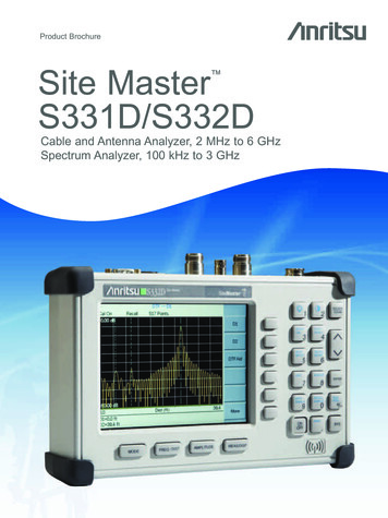
Antenna Mask (Example 1)Typical relativedirectivity- maskof receivingantenna (Yagiant., TV dcmwaves)-5-10-15180120600-60-120-20-180Relative gain, dB0[CCIR doc. 11/645, 17-Oct 1989)Azimith angle, degreesR Struzak50
Antenna Mask (Example 2)00dBRR/1998 APS30 Fig.9Relative gain 00Phi/Phi0Reference pattern for co-polar and cross-polar components forsatellite transmitting antennas in Regions 1 and 3 (Broadcasting 12 GHz)R Struzak51
VoltsEquivalent half-power beamwidth representationsof an antenna’s radiation pattern.R Struzak52
Anisotropic sources: gainHypothetic directionalantennaHypotheticisotropicantennaEvery real antenna radiates moreenergy in some directions than inothers (i.e. has directional properties) Idealized example of directionalantenna: the radiated energy isconcentrated in the yellow region(cone). Directive antenna gain: the power fluxdensity is increased by (roughly) theinverse ratio of the yellow area and thetotal surface of the isotropic sphere– Gain in the field intensity may also beconsidered - it is equal to the squareroot of the power gain.R Struzak53
Plane angle: radian Angle in radians,lω ω*rω lω / r;lωrω– lω is the length of the arcsegment supported by theangle ω in a circle of radius r.– There are 2π rad in a fullcircle– 1 rad (360 / 2π) degR Struzak54
Solid angle: steradian Solid angle in steradians (sr),Ω (SΩ)/r2; SΩ Ωr2SΩ is the spherical surface area supportedby the solid angle Ω in a sphere of radius r The steradian is the area cut out by the solidangle, divided by the sphere’s radiussquared - ‘squared radian’. If the area is S, and the radius is d, then theangle is S/d2 steradians. The total solidangle (a full sphere) is thus 4π steradians. As one radian is 180/π 57.3 degrees, thetotal solid angle is 4π x (57.3)2 41253square degrees, one steradian is 3282.806square degrees, and one square degree isabout 305 x 10-6 steradiansR Struzak55
Example: gain of 1 deg2 antennaP/αd2 α sr IsotropicP/(4πd2) G 4π/α If α 1 deg2, thenA hypothetical source radiates Pwatts uniformly within the solid angleof α steradians in a given directionand zero outsideThe total surface of the sphere is4πd2 and the average irradiance isthe power divided by the surface:[P/(4πd2)] w/m2α steradians corresponds tospherical surface of αd2 andirradiance within that angle is[P/αd2] w/m2The antenna gain equals the ratio ofthese two, or 4π/αFor α 1 deg2 ( 305*10-6 sr); thegain 4π/305*10-6 46 dB. ,G 4π/305*10-6 46 dBR Struzak56
Effect of sidelobesLet the main beamwidth of an antenna be Ω square degrees, with uniform irradiance ofW watts per square meter. Let the sidelobe irradiance (outside the main beam) beuniform and k times weaker, i.e. (W/k) watts per square meter, k 1. Then:WW/kG .The gain decreases with the sidelobelevel and beamwidth.If the main lobe is 1 square degree andthe sidelobes are attenuated by 20 dB,then k 100 and G 100 (or 20dB) ,much less than in the previous example(46dB).In the limit, when k 1, the gain tends to1 (isotropic antenna).W1 W0 1 k 1 Ω k k 41253 R Struzak57
PM W Ωd 2- power radiated within the main lobe W PS ( 41253 Ω ) d 2 - power radiated by sidelobes k 41253 Ω 2 - total powerPT PM PS Wd Ω kk PT 1 kΩ Ω W0 W 2 41253d41253kk 1WG W0 1 k 1 Ω k k 41253 - average irradiation- antenna gain.R Struzak58
Antenna gain measurementReferenceantennaMeasuringequipmentPo Powerdelivered tothe referenceantennaS0 Powerreceived(the same inboth steps)ActualantennaP Powerdelivered tothe actualantennaStep 1: referenceMeasuringequipmentS Powerreceived(the same inboth steps)Step 2: substitutionAntenna Gain (P/Po) S S0R Struzak59
Antenna Gains Gi, Gd Unless otherwise specified, the gain refersto the direction of maximum radiation. Gain is a dimension-less factor related topower and usually expressed in decibels Gi “Isotropic Power Gain” – theoreticalconcept, the reference antenna is isotropic Gd - the reference antenna is a half-wavedipoleR Struzak60
Typical Gain and BeamwidthType of antennaGi [dB]BeamW.Isotropic03600x3600Half-wave Dipole23600x1200Helix (10 turn)14350x350Small dish16300x300Large dish4510x10R Struzak61
Gain, Directivity, RadiationEfficiency The radiation intensity, directivityand gain are measures of theability of an antenna toconcentrate power in a particulardirection.Directivity relates to the powerradiated by antenna (P0 )Gain relates to the powerdelivered to antenna (PT)G (ϑ , ϕ ) ηD(ϑ , ϕ )PTη P0 η: radiation efficiency(0.5 - 0.75)R Struzak62
Antenna gain and effective area Effective area: Measure of the effectiveabsorption area presented by an antenna to anincident plane wave. Depends on the antenna gain and wavelengthλ2Ae ηG (θ , ϕ ) [m ]4π2Aperture efficiency: ηa Ae / AA: physical area of antenna’s aperture, square metersR Struzak63
Power Transfer in Free Space PR PFD Ae GT PT 2π4r λ GR 4π 2 λ PT GT GR 4πr 2R Struzak λ: wavelength [m]PR: power available at thereceiving antennaPT: power delivered to thetransmitting antennaGR: gain of the transmittingantenna in the direction ofthe receiving antennaGT: gain of the receivingantenna in the direction ofthe transmitting antennaMatched polarizations64
e.i.r.p. Equivalent Isotropically RadiatedPower (in a given direction):e.i.r. p. PGi The product of the power supplied to theantenna and the antenna gain (relativeto an isotropic antenna) in a givendirectionR Struzak65
Linear Polarization In a linearly polarizedplane wave the directionof the E (or H) vector isconstant .R Struzak66
Polarization ellipseExEyMψN The superposition of twocoherent plane-wavecomponents results in anelliptically polarized wave The polarization ellipse isdefined by its axial ratioN/M (ellipticity), tilt angleψ and sense of rotation Polarization (Java mlR Struzak67
Elliptical PolarizationLHCEx cos (wt)Ey cos (wt)Ex cos (wt)Ey cos (wt pi/4)Ex cos (wt)Ey -sin (wt)RHCEx cos (wt)Ey -cos (wt pi/4)R StruzakEx cos (wt)Ey cos (wt 3pi/4)Ex cos (wt)Ey sin (wt)68
Polarization statesLHCUPPER HEMISPHERE:ELLIPTIC POLARIZATIONLEFT HANDED SENSELATTITUDE:REPRESENTSAXIAL RATIOEQUATOR:LINEAR POLARIZATIONLOWER HEMISPHERE:ELLIPTIC POLARIZATIONRIGHT HANDED SENSEPOLES REPRESENTCIRCULAR POLARIZATIONS(Poincaré sphere)450 LINEARRHCR StruzakLONGITUDE:REPRESENTSTILT ANGLE69
Comments on Polarization At any moment in a chosen reference point inspace, there is actually a single electric vector E(and associated magnetic vector H). This is the result of superposition (addition) ofthe instantaneous fields E (and H) produced byall radiation sources active at the moment. The separation of fields by their wavelength,polarization, or direction is the result of ‘filtration’.R Struzak70
Antenna Polarization The polarization of an antenna in a specificdirection is defined to be the polarization of thewave produced by the antenna at a greatdistance at this directionR Struzak71
Polarization Efficiency The power received by an antennafrom a particular direction is maximal if thepolarization of the incident wave and thepolarization of the antenna in the wave arrivaldirection have:– the same axial ratio– the same sense of polarization– the same spatial orientation.R Struzak72
Polarization filters/ reflectorsWall of thin parallel wires (conductors) E1 0 E1 0 E2 0 E2 E2 Vector E wiresVector E wiresReflectingTransparentWire distance 0.1λ At the surface of ideal conductor the tangentialelectrical field component 0R Struzak73
Outline IntroductionReview of basic antenna typesRadiation pattern, gain, polarizationEquivalent circuit & radiation efficiencySmart antennasSome theorySummaryR Struzak74
Transmitting antenna equivalent circuitAntennaTransmitterTransm. lineRadio waveThe transmitter with the transmission line is represented by an(Thevenin) equivalent generatorjXARGVGGeneratorjXGRrThe antenna is represented by its input impedance(which is frequency-dependent and is influenced by objectsnearby) as seem from the generatorjXA represents energy stored in electric (Ee) and magnetic (Em)near-field components; if Ee Em then XA 0 (antennaresonance)Rr represents energy radiated into space (far-field components)Rl represents energy lost, i.e. transformed into heat in theantenna structureRlNote: Transmission-line model offers better approximationR Struzak75
Power transfer: Tx antennaTransmitter is represented by an eqivalentgenerator with VG , RG , X G const.Let RA RR RL ; RA , X A var.jXARGVGGeneratorjXGRRThe power absorbed by antenna P I 2 RA I2 P VG2RL VG 22( RG RA ) ( XG X A ) RA( RG RA ) ( XG X A )222RARG VG2 P 22 RG RA X G X A 1 RRRG G GR Struzak76
P VG2( RG RA )RA2Let X G X A 0. Then P VG2 X G2 2 X G X A X A2 RA ( 2 X G 2 X A ) P VG2 22 2 X A RRXX ( G( G A ) A) P 0, when X A X G X AMaximum : P P 0 RA X ARA RG ,X A XGRA( RG RA )2 2 RRRRR2()() P AAGA VG2 G2 2 RA ( RG RA ) 2 22 R 2 RG RA RA 2 RG RA 2 RA VG2 G 2 2 R RA ) ( G P 0, when RG RA RAVG2P 4 RGR Struzak77
Impedance matchingRA Rr Rl RgX A XgPA Pg Vg24 RAVg24 Rg( PA )Pr PARr( Rr Rl )Pl PARl( Rr Rl )R Struzak78
Power vs. field strengthPr E2 E Pr Z 0Z0E Eθ Eϕ2H 2EZ0Z 0 377 ohmsfor plane wavein free spaceR Struzak79
Receiving antenna equivalent circuitAntennaRadio waveTransm.lineReceiverThe antenna with the transmission line is representedby an (Thevenin) equivalent generatorRrRlAntennajXAjXLRLThe receiver is represented by its input impedance asseen from the antenna terminals (i.e. transformed bythe transmission line)VA is the (induced by the incident wave) voltage at theantenna terminals determined when the antenna isopen circuitedNote1: The antenna impedance is the same when the antenna is used toradiate and when it is used to receive energyVAThevenin equivalentNote 2: Transmission-line model offers better approximationR Struzak80
Power transferPA / PAmax10.500.11RA / RG; (XA XG 0)10 The maximumpower is deliveredto (or from) theantenna when theantennaimpedance and theimpedance of theequivalentgenerator (or load)are matchedR Struzak81
When the impedances are matched– Half of the source power is delivered to the load andhalf is dissipated within the (equivalent) generator asheat– In the case of receiving antenna, a part (Pl) of thepower captured is lost as heat in the antennaelements, the other part being reradiated (scattered)back into space Even when the antenna losses tend to zero, still only half ofthe power captured is delivered to the load (in the case ofconjugate matching), the other half being scattered back intospaceR Struzak82
The antenna impedance must be matchedto the transmitter output impedance (or tothe receiver input impedance) and totransmission line between them to assureeffective power transfer Inexpensive impedance-matching devicesare usually narrow-bandR Struzak83
Radiation efficiency The radiation efficiency e indicates howefficiently the antenna uses the RF power It is the ratio of the power radiated by theantenna and the total power delivered tothe antenna terminals (in transmittingmode). In terms of equivalent circuitparameters:Rre Rr RlR Struzak84
Outline IntroductionReview of basic antenna typesRadiation pattern, gain, polarizationEquivalent circuit & radiation efficiencySmart antennasSome theorySummaryR Struzak85
Antenna arrays Consist of multiple (usually identical) antennas(elements) ‘collaborating’ to synthesize radiationcharacteristics not available with a single antenna. Theyare able– to match the radiation pattern to the desired coverage area– to change the radiation pattern electronically (electronicscanning) through the control of the phase and the amplitude ofthe signal fed to each element– to adapt to changing signal conditions– to increase transmission capacity by better use of the radioresources and reducing interference Complex & costly– Intensive research related to military, space, etc. activities» Smart antennas, signal-processing antennas, tracking antennas,phased arrays, etc.Source: adapted from N GregorievaR Struzak86
Satellite antennas (TV) Not an array!R Struzak87
Owens Valley RadioObservatory ArrayThe Earth’satmosphere istransparent inthe narrowvisible-lightwindow(4000-7000angstroms) andthe radio bandbetween 1 mmand 10 m.[Sky & TelescopeFeb 1997 p.26]R Struzak88
New Mexico Very Large Array[Sky & TelescopeFeb 1997 p. 30]27 antennas along 3 railroad tracks provide baselines up to 35 km.Radio images are formed by correlating the signals garnered byeach antenna.R Struzak89
2 GHz adaptive antenna array A set of 482 GHzantennas– Source:ArraycommR Struzak90
Phased Arrays Array of N antennas in a linear or twodimensional configuration beam-forming& control device The amplitude and phase excitation of eachindividual antenna controlled electronically(“software-defined”)– Diode phase shifters– Ferrite phase shifters Inertia-less beam-forming and scanning (µsec)with fixed physical structureR Struzak91
Simulation 2 omnidirectional antennas (equalamplitudes)– Variables distance increment phase increment N omnidirectional antennas– Group factor (N omnidirectional antennasuniformly distributed along a straight line,equal amplitudes, equal phase increment)R Struzak92
2 omnidirectional 1-0.5-0.5-0.5-1-1-1D 0.5λ, θ 900D 0.5λ, θ 1800D 0.5λ, θ 00 000-1Java applet 2 antennas:Simple demo: 2-2.htmlDetailed analysis: -2.htmlR Struzak93
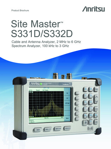
N omnidirectional antennas62.510952871Relative gain1.5Relative gainRelative gain4320.565432110-1800-90090Azimuth angle, degreesN 2, θ 900180-180-90090Azimuth angle, degreesN 5, θ 18001800-180-90090180Azimuth angle, degreesN 9, θ 450 Array gain (line, uniform, identical power)R Struzak94
Switched beam antennas– Based on switching function betweenseparate directive antennas orpredefined beams of an array Space Division Multiple Access(SDMA) allocating an angledirection sector to each user– In a TDMA system, two users will beallocated to the same time slot andthe same carrier frequency– They will be differentiated by differentdirection anglesR Struzak95
Dynamically phased array(PA):– A generalization of theswitched lobe concept– The radiation patterncontinuously track thedesignated signal (user)– Include a direction of arrival(DoA) tracking algorithmR Struzak96
Beam SteeringBeam directionθEqui-phasewave frontd3 [(2π/λ)d sinθ]2 0RadiatingelementsPhaseshifters Beamsteeringusingphaseshifters ateachradiatingelementPowerdistributionR Struzak97
4-Bit Phase-Shifter (Example)Bit #3Bit #4Input00or22.5000or450Bit #1Bit #200or90000or1800OutputSteering/ Beam-forming CircuitryAlternative solution: Transmission line with controlled delayR Struzak98
Switched-Line Phase BitDelay line #1aInputDiode switchOutputDelay line #1bPhase bit delay differenceR Struzak99
Antenna Arrays: Benefits Possibilities to control electronically–––––Direction of maximum radiationDirections (positions) of nullsBeam-widthDirectivityLevels of sidelobesusing standard antennas (or antenna collections)independently of their radiation patterns Antenna elements can be distributed alongstraight lines, arcs, squares, circles, etc.R Struzak100
Adaptive (“Intelligent”)Antennas Array of N antennas in a linear,circular, or planar configuration Used for selection signals fromdesired sources and suppressincident signals from undesiredsources The antenna pattern track thesources It is then adjusted to null out theinterferers and to maximize thesignal to interference ratio (SIR) Able to receive and combineconstructively multipath signalsR Struzak101
The amplitude/ phaseexcitation of eachantenna controlledelectronically(“software-defined”) The weight-determiningalgorithm uses a-prioriand/ or measuredinformation to adaptantenna to changingenvironment The weight andsumming circuits canoperate at the RF and/or at an orithmR Struzak102
Antenna sitting Radio horizon Effects of obstacles & structures nearby Safety– operating procedures– Grounding lightning strikes static charges– Surge protection lightning searches for a second path to groundR Struzak103
Outline IntroductionReview of basic antenna typesRadiation pattern, gain, polarizationEquivalent circuit & radiation efficiencySmart antennasSome theorySummaryR Struzak104
Maxwell’s Equations EM field interacting wi
archive/wavesA.html -Elliptical polarization: change of the rotation sense! R Struzak 22 Planar reflectors Uda-Yagi, Log-periodic antennas d 2d Intended reflector antenna allows maintaining radio link in non-LOS conditions (avoiding propagation obstacles) Unintended reflector antennas